1
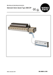
Mounting and Operating Instructions Solenoid Valves Type 3963 Fig. 1 General Assembly, commissioning and operation of these devices may only be performed by experienced personnel. Proper shipping and appropriate storage are assumed. The air supply may not exceed the maximum permissible pressure and, if necessary, it must be limited by a pressure reducer. The devices can be mounted in any desired position. The filter in the enclosure cover and the cable gland Pg 13.5 must be installed hanging downwards, or if this is not possible, horizontally. On mounting, it is important that a clearance of ≥ 300 mm above the enclosure cover is kept. If the device is mounted to a rotary actuator or linear actuator with positioner, it is necessary to change over the air supply to an external supply at connection 9 (see page 7 ff.). The minimum permissible ambient temperature is Ҁ25 °C (for Type 3963-....0/-....2 and 3756-1203/-6203) and Ҁ40 °C (for Type 3963-....1/-....3 and 3756-1213/-6213/ -3…/-8…). Edition: May 1998 The maximum permissible ambient temperature of ѿ80 °C is lowered for intrinsically safe devices in accordance with the Certificate of Conformity PTB No. Ex-90.C.2100 (see page 10). Technical data, ordering data, spare parts and accessories see Data Sheet T 963 EN. Contents General Mounting Air connection Electrical connection Certificate of Conformity PTB No. Ex-90.C.2100 (Extract) Installation directions for devices for use in hazardous locations in compliance with CSA approval Installation directions for devices for use in hazardous locations in compliance with FM approval Addendum to T 963 EN Page 1 Page 2 Page 6 Page 9 Page 10 Page 12 Page 13 EB 963 EN Mounting Mounting base for G-profile 32 (Order No. 1400-5930) Mounting rails 38 Type 3963-..14/-..27/-..28/-..54/-..64 These devices can be attached with two mounting bases for G-profile 32 according to EN 50 035 or top hat rail 35 according to EN 50 022 (Fig. 2). M 3 x 8 DIN 84 63 Mounting base for top hat rail 35 (Order No. 1400-5931) Wall mounting Type 3963-..14/-..27/-..28/-..54/-..64 These devices can be attached to a wall mounting plate (Fig. 2). 38 M 3 x 8 DIN 84 Type Type Type Type 3963-..25, combined with 3756-1203/-6203/-1213/-6213 3963-..76, combined with 3756-3205/-8205/-3206/-8206/ -3325/-8325/-3335/-8335/ -3345/-8345/-3355/-8355 These devices can be attached with screws through bore holes (Fig. 3). 63 Wall mounting plate (Order No. 1400-6726) ø6 38 25 M 3 x 8 DIN 912 63 82 94 Fig. 2 · Dimensions in mm 4 2 3 7 32 50.8 21 21 52 32 61 Fig. 3 · Dimensions in mm EB 963 EN 4 30 52 5 5 1 –2– 63 4.3 4.3 22 189 3 29 63 29 5 1 3 4 32 2 50.8 244 29 169 63 Type 3963-..76, combined with Type 3756-3205/-8205/-3206/-8206/ -3325/-8325/-3335/-8335/ -3345/-8345/-3355/-8355 22 Type 3963-..25, combined with Type 3756-1203/-6203/-1213/-6213 Mounting to rotary actuators with NAMUR interface according to VDI/VDE 3845 NAMUR interface according to VDI/VDE 3845 24 왘 Type 3963-..11/-..12/-..21/-..22/-..23/ -..52/-..62 왘 Type 3963-..76, combined with Type 3756-3207/-8207/-3208/-8208/ -3327/-3827/-3337/-3837/ -3347/-3847/-3357/-3857 These devices can be directly attached to rotary actuators with NAMUR interface (Fig. 4). Before mounting, check that the two O rings are positioned correctly. The operation direction is determined by a threaded coding pin M 5 ҂10 DIN 916 on the mounting flange of the rotary actuator. The device is attached with two screws M 5 ҂35 DIN 912. The mounting accessories are delivered together with the device. 32 Threaded coding pin G 1/4 왘 Type 3963-..76, combined with Type 3756-3207/-8207/-3208/-8208 These devices can be attached to a restrictor block for rotary actuators with NAMUR interface (Fig. 5). The restricting function can be identified from the symbol indicated on the device. Different closing and opening times can be adjusted in a ratio of 1:15 by turning the restricting screws to the left or to the right respectively with a screw driver. 96 29 9 5 3 5 4 1 1 2 47 2 25.4 5 1 1 55 9 5 4 72 63 47 63 Mounting to restrictor block for double-acting rotary actuators (Order No. 1400-6764) 122 29 Fig. 4 · Dimensions in mm 122 Mounting to restrictor block for single-acting rotary actuators (Order No. 1400-6763) M5 2 8 12 Mounting to restrictor block for rotary actuators with NAMUR interface according to VDI/VDE 3845 3 75 55 25.4 40 Fig. 5 · Dimensions in mm –3– EB 963 EN Mounting with adapter plate to linear actuators with NAMUR rib according to DIN IEC 534 Adapter plate NAMUR rib/NAMUR interface (Order No. 1400-6751) 60 30 1.3 92 2.3 G1/2 30 15 10 Mounting with screwed pipe connection of CrNiMo to linear actuators 25 12 12 25 2.3 M 8 x 35 DIN 912 32 왘 Type 3963-..27/-..28/-..54 왘 Type 3963-..25, combined with Type 3756-1203/-1213 왘 Type 3963-..76, combined with Type 3756-3205/-3206 These devices can be mounted with a screwed pipe connection to linear actuators, e. g. SAMSON Type 271 or 3277 (Fig. 7). Mounting instructions for SAMSON devices see Mounting and Operating Instructions EB 8310 EN and EB 8311 EN. ø8 1.3 M 5 14 왘 Type 3963-..11/-..12/-..21/-..22/-..23/ -..52/-..62 왘 Type 3963-..76, combined with Type 3756-3207/-3208 These devices can be mounted with an adapter plate (Fig. 6) to linear actuators with NAMUR rib. When positioners or limit switches with long lever are to be mounted on linear actuators ≤ DN 50 at the same time a bracket (Order No. 0320-1416) is required. Fig. 6 · Dimensions in mm 45 A Mounting with screwed pipe connection of CrNiMo to linear actuators 97 Actuator size Connection A Order No. 80/240 cm 2 G 1/4 / 1/4 64 1400-6759 350/700 cm 2 G 3/8 / 1/4 75 1400-6761 G 3/8 / 1/2 64 1400-6735 Actuator size 1400 cm 2 2100 cm 2 2800 cm 2 Fig. 7 · Dimensions in mm EB 963 EN –4– Connection G 3/4 / 1/2 G 1 / 1/2 Order No. 1400-6736 1400-6737 Mounting to connection block for Linear Actuator SAMSON Type 3277 Mounting to linear actuators with NAMUR rib according to DIN IEC 534 왘 Type 3963-..29/-..55 These devices can be mounted to connection block for Linear Actuator SAMSON Type 3277 with Positioner SAMSON Type 3766, 3767 or 3780 (Fig. 8). Before mounting, check that the four O-rings are positioned correctly on the mounting flange. The device is attached with two screws M 5 ҂60 DIN 912. The mounting accessories are delivered together with the device. Mounting instructions for SAMSON devices see Mounting and Operating Instructions EB 8311 EN, EB 8355 EN and EB 8380 EN. 왘 Type 3963-..53 These device can be directly mounted to a linear actuator with NAMUR rib. The device is attached with one screw M 8 ҂45 DIN 912 which is delivered with the device. Mounting to connection block for Linear Actuator SAMSON Type 3277 B A Connection block for actuator "stem extends" (Order No. 1400-6943/-6944), actuator "stem retracts" (Order No. 1400-6945/-6946), with piping kit (Order No. 1400-6444/-6445/ -6446/-6447) Type 3963-..29/-..55 A-B 29 ≥ 390* 190 Mounting flange *Clearance for mounting of enclosure cover 90 Fig. 8 · Dimensions in mm –5– EB 963 EN Air connection Working medium The air supply pipes and screw joints may only be laid and assembled by experienced personnel. They must be regularly checked for leaks and damage, and if necessary, repaired. Before starting any repair work, all supply pipes which are to be opened must be depressurized. The air connections are G (NPT) 1/4 or G (NPT) 1/2 tapped holes depending on the version. Note: The K vs value of a pressure reducer connected upstream must be at least 1.6 times larger than the K vs value of the device. Supply pipe Nominal size (Supply pipe length ≤ 2 m) Press- K vs value ure 0.16 1.4 4.3 – 0.32 Connection (bar) 4 1 and 3 4 9 ≥ 1.4 ≥ DN 6 ≥ DN 8 ≥ DN 10 ≥ DN 4 ≥ 2.5 ≥ DN 4 ≥ DN 6 ≥ DN 8 ≥6 ≥ DN 4 ≥ DN 6 Instrument air 1.4 … 6 bar for internal air supply (as-delivered condition). Instrument air, oil-containing air or nonaggressive gases of 0 … 6 bar (10 bar with Type 3756) for external air supply across connection 9 (see page 7 ff.). Exhaust air restrictors 왘 Type 3963-..12/-..22/-..23/-..28/-..29 These devices have one or two exhaust air restrictors. The restricting function can be identified from the symbol indicated on the device. Different closing and opening times can be adjusted in a ratio of 1:15 by turning restricting screws to the right or to the left respectively with a screw driver. The restricting screws can be found underneath the enclosure cover or at the adapter plate (Fig. 9). Setting of the exhaust air restrictors _ + 1.3 2.3 Note: For supply pipes length ≥ 2 m larger nominal sizes must be provided. 왘 Type 3963-..25, combined with Type 3756-1203/-6203/-1213/-6213 With the above listed devices, it is possible to check whether the nominal size of the supply pipe is sufficient as follows: 1. Unscrew the screw plug covering connection 9 and connect a pressure gauge. 2. The nominal size of the supply pipe proves to be sufficient when there is a pressure of ≥ 1.3 bar during the switching process. Air supply instrument air 1.4 … 6 bar Ambient Particle Dew Oily temperature size point residues (°C) (µm) (°C) (mg/m 3) ѿ15 … ѿ35 ≤ 5 ѿ10 ≤ 0.1 Ҁ15 Ҁ20 Ҁ32 Ҁ40 Ҁ60 Ҁ70 EB 963 EN Manual operation (optionally) Type 3963-..12/-..22/-..28/-..29 4 1.3 Type 3963-..23 Fig. 9 –6– Conversion to external air supply across connection 9 Installation of flat gasket [1] 왘 Type 3963-..25, combined with Type 3756-1203/-6203/-1213/-6213 To these devices air supply in the as-delivered condition is to be connected internal via connection 4. Conversion to external air supply via connection 9 is effected as follows: 1. Remove pilot valve enclosure cover after removal of four filister head screws. 2. Remove pilot valve from booster valve after removal of three hexagon socket head screws. 3. Remove plate with flat gasket [1] after removal of a filister head screw (Fig. 10). 4. Turn flat gasket [1] by 90°. After assembly, the tab of the gasket [1] is not visible from the outside. 5. Conversion to external air supply is determined only by turning the flat gasket [1]. Prior to assembly, install flat gasket [3] between pilot valve and booster valve as follows (Fig. 12): Type 3963 with index -01, -02, -04 and -06 The white mark in the slots of the flat gasket [3] is not visible. Type 3963 with index -03, -05 and -10 The tab of the flat gasket [3] is placed in cutout “Int“ of the enclosure. [1] Fig. 10 Installation of flat gasket [2] 왘 Type 3963-..76, combined with Type 3756-3205/-8205/-3206/-8206/ -3207/-8207/-3208/-8208/ -3325/-8325/-3327/-8327/ -3335/-8335/-3337/-8337/ -3345/-8345/-3347/-8347/ -3355/-8355/-3357/-8357 To these devices air supply in the as-delivered condition is to be connected internal via connection 1 or 3. Conversion to external air supply via connection 9 is effected as follows: 1. Remove plate with flat gasket [2] from the connecting plate after removal of a filister head screw. 2. Turn flat gasket [2] by 180°. The tab of flat gasket [2] is then placed in cutout “9“ of the connecting plate (Fig. 11). Note: In the case of bilaterally actuated booster valves, both pilot valves must be converted. [2] Fig. 11 –7– EB 963 EN 왘 Type 3963-..14/-..52/-..53/-..54 To these devices air supply in the as-delivered condition is to be connected internal via connection 4. Conversion to external air supply via connection 9 is effected as follows: 1. Remove enclosure cover after removal of four filister head screws. 2. Remove solenoid valve from adapter plate after removal of three hexagon socket head screws. Type 3963 with index -01, -02, -04 and -06 3. Turn flat gasket [3] by 180°. The white mark is then visible in the slots (Fig. 12). Type 3963 with index -03, -05 and -10 Turn flat gasket [3] by 180°. The tab of the flat gasket [3] is then placed in cutout “9“ of the enclosure (Fig. 12). 왘 Type 3963-..11/-..12/-..21/-..22/-..27/ -..28/-..29/-..55/-..62 To these devices the air supply cannot be changed. The flat gasket [3], if provided, must be installed in accordance with the asdelivered condition (Fig. 12). Exhaust air return 왘 Type 3963-..76, combined with Type 3756-3206/-8206 To these devices, in the as-delivered condition connection 4 is closed with a threaded plug. If the exhaust air return is used for spring-loaded actuators, the threaded plug must be removed and connection 4 must be connected to the spring chamber of the actuator by a hose with nominal size DN 4 to 10 (depending on the actuator size). Installation of flat gasket [3] Type 3963 with index -01, -02, -04 and -06 [3] [3] Internal air supply External air supply via connection 4 via connection 9 (as-delivered condition) Type 3963 with index -03, -05 and -10 [3] [3] Int 9 Internal air supply External air supply via connection 4 via connection 9 (as-delivered condition) Fig. 12 EB 963 EN –8– Electrical connection Connection diagrams 82 _ Terminals in the enclosure 8 7 6 2 5 4 3 + _ brown The power supply is connected, depending on version, either through a cable gland Pg 13.5 to the terminals in the enclosure, with a Harting connector, a socket in accordance to DIN 43 650 or a cable socket M 12 ҂1 (Fig. 13). 81 + blue As far as the electrical installation of the device is concerned, the relevant VDE regulations and the accident prevention regulations of the employers´ liability insurance association must be observed. For installation in hazardous areas, the respective national regulations of the country in which the device is to be used must be observed. In Germany this is VDE 0165. When connected to DC voltage signals, correct polarity must be ensured. For connection of intrinsically safe circuits, the Certificate of Conformity PTB No. Ex-90.C.2100 applies (see page 10). The coated screws in the enclosure may not be tampered with. Harting connector Cable It is recommended that connecting cables with a conductor cross-section of ≥ 0.5 mm 2 are used. Connecting cables with an external diameter of 6 … 12 mm are suitable for the cable gland Pg 13.5. _ 2 1 + blue brown 3 Degree of protection Socket in accordance to DIN 43 650 Manual operation _ –9– + 2 1 blue The devices have a manual operation as an alternative to allow the device to be manually operated when a nominal signal is not available: – Switch outside of the enclosure – Push button outside of the enclosure – Switch in the enclosure cover – Pushbutton underneath enclosure cover (see page 6, fig. 9) Note: For safety circuits, only devices without manual operation should be used. 3 4 brown The devices can be changed from degree of protection IP 54 (Order No. 8504-0066) to degree of protection IP 65 (Order No. 10991103) by exchanging the filter in the enclosure cover. Cable socket M 12 ҂1 Fig. 13 EB 963 EN Certificate of Conformity PTB No. Ex-90.C.2100 (Extract) for the electric apparatus Solenoid Valve Type 3963-1... index -02 and -03 Class EEx ia IIC T6 dated 06.09.1990 1. Addendum dated 28.06.1991 2. Addendum dated 11.04.1994 3. Addendum dated 10.10.1995 The following table shows the maximum permissible ambient temperature within the temperature classes: Nominal signal Type 6 12 24 22 7.5 3963-11 3963-12 3963-13 3963-14 3963-17 V V V mA V Permissible maximum ambient temperature T6 T5 T4 ѿ60 °C ѿ70 °C ѿ80 °C ѿ65 °C ѿ80 °C Note: Minimum permissible ambient temperature Ҁ45 °C. This is limited to Ҁ25 °C (for Type 39631...0/-1…2) and Ҁ40 °C (for Type 3963-1...1/-1…3) due to the materials used. To connect to a certified intrinsically safe electric circuit, refer to the maximum permissible values for voltage U 0, current I k and power P in the following table: Type U 0 (V) I k (mA) P (mW) 3963-11 13 27 150 125 *) 400 3963-12 25 28 150 115 *) 400 3963-13 32 32 70 90 *) 250 28 115 *) *) No power limit Note: Internal capacitance and internal inductance are negligible. EB 963 EN – 10 – 3963-14 8 15 150 200 *) 400 3963-17 28 32 115 90 *) 350 Certificate of Conformity PTB No. Ex-90.C.2100 (Extract) for the electric apparatus Solenoid Valve Type 3963-1... index -04 and up Class EEx ia IIC 4. Addendum dated 11.07.1997 The following table shows the maximum permissible ambient temperature within the temperature classes: Temperature class Ambient temperature maximum minimum T6 ѿ60 °C Ҁ45 °C *) T5 ѿ70 °C T4 ѿ80 °C *) Limited to Ҁ25 °C (for Type 3963-1...0/-1…2) and Ҁ40 °C (for Type 3963-1...1/-1…3) due to the materials used. To connect to a certified intrinsically safe circuit, refer to the maximum permissible values for voltage U 0, current I 0 and power P in the following table: U 0 (V) I 0 (mA) P 25 V 150 mA no power limit 27 V 125 mA 28 V 115 mA 30 V 100 mA 32 V 90 mA Note: Internal capacitance and internal inductance are negligible. – 11 – EB 963 EN Installation Directions for Devices for Use in Hazardous Locations in Compliance with CSA Approval Type The devices may be installed in intrinsically safe circuits when connected with CSA approved intrinsically safe barriers (Fig. 14). In case of doubt as regards barrier selection, contact the manufacturer. For maximum values of V max, R min and I max of the various devices see the following table: V max [V DC] 13 25 28 9 28 3963-31 3963-32 3963-33 3963-34 3963-37 R min [Ω] 94 168 256 60 256 I max [mA] 150 150 110 150 110 Connection diagrams CSA certified for Hazardous Locations: Class I; Division 1; Groups A, B, C, D Hazardous Location Safe Location I.S. barrier + Solenoid Valve Type 3963-3... I.S. circuit _ + Supply barrier _ to instrument Return barrier *) Ground *) Only for metal enclosure Cable entry Pg 13,5 or metal conduit according to assembly drawing No. 3963-3... and drawing No. 1150-6016 T-3 CSA certified for Hazardous Locations: Class I; Division 2; Groups A, B, C, D Safe Location Hazardous Location Solenoid Valve Type 3963-3... + _ _ + *) Ground *) Only for metal enclosure Cable entry only rigid metal conduit according to drawing No. 1150-6016 T-3 Fig. 14 EB 963 E – 12 – Unspecified apparatus, e.g. transistor relay, with output parameters per table Installation Directions for Devices for Use in Hazardous Locations in Compliance with FM Approval Type The devices may be installed in intrinsically safe circuits when connected with FM approved intrinsically safe barriers (Fig. 15). In case of doubt as regards barrier selection, contact the manufacturer. For maximum values of V max and I max of the various devices see the following table: V max [V DC] 13 25 28 9 28 3963-31 3963-32 3963-33 3963-34 3963-37 I max [mA] 150 150 110 150 110 Connection diagrams FM certified for Hazardous Locations: Class I, II, III; Division 2; Groups A, B, C, D, E, F, G Hazardous Location Safe Location I.S. barrier + Solenoid Valve Type 3963-3... I.S. circuit _ to instrument *) Ground *) Only for metal enclosure FM certified for Hazardous Locations: Class I, II, III; Division 1; Groups A, B, C, D, E, F, G Safe Location Hazardous Location Solenoid Valve Type 3963-3... + _ _ + *) Unspecified apparatus, e.g. transistor relay, with output parameters per table Ground *) Only for metal enclosure Fig. 15 – 13 – EB 963 EN SAMSOMATIC AUTOMATIONSSYSTEME GMBH – A subsidiary of SAMSON AG Weismüllerstrasse 20 – 22 D-60314 Frankfurt am Main P. O. Box 10 19 01 D-60019 Frankfurt am Main Telephone +49-69-4 00 90 Telefax +49-69-4 00 96 44 A. (Specifications subject to change without notice)