1
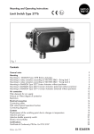
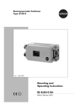
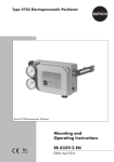
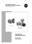
Electropneumatic Positioner
Type 4763
Fig. 1 · Type 4763
Mounting and
Operating Instructions
EB 8359-2 EN
Edition September 2004
Contents
Contents
1
Design and principle of operation . . . . . . . . . . . . . . . . . . . . 6
2
2.1
2.2
2.3
Attachment . . . . . . . . . . . . . . .
Attachment to valves with cast yokes . . .
Attachment to valves with rod-type yokes
Cover of the positioner case . . . . . . .
3
3.1
3.2
3.2.1
3.2.2
Connections . . . . . .
Electrical connections .
Pneumatic connections .
Pressure gauges . . . .
Supply pressure . . . .
.
.
.
.
.
.
.
.
.
.
.
.
.
.
.
.
.
.
.
.
.
.
.
.
.
.
.
.
.
.
.
.
.
.
.
.
.
.
.
.
.
.
.
.
.
.
.
.
.
.
.
.
.
.
.
.
.
.
.
.
.
.
.
.
.
.
.
.
.
.
.
.
.
.
.
.
.
.
.
.
.
.
.
.
.
.
.
.
.
.
.
.
.
.
.
.
.
.
.
.
.
.
.
.
.
.
.
.
.
.
.
.
.
.
.
.
.
.
.
.
.
.
.
.
.
.
.
.
.
.
.
.
.
.
.
10
10
11
11
11
4
4.1
4.1.1
4.2
4.3
4.3.1
4.3.2
4.3.3
4.4
Operation . . . . . . . . . . . . . . . . . . . . . . . . . . . . . .
Combining positioner and actuator. . . . . . . . . . . . . . . . . .
Determining/reversing the operating direction . . . . . . . . . . . .
Starting point and input signal (reference variable) . . . . . . . . . .
Setting the positioner at the valve. . . . . . . . . . . . . . . . . . .
Setting the air delivery (volume restriction Q) and proportional band XP
Setting actuator version “Stem extends” . . . . . . . . . . . . . . .
Setting actuator version “Stem retracts” . . . . . . . . . . . . . . . .
Exchanging the range spring. . . . . . . . . . . . . . . . . . . . .
.
.
.
.
.
.
.
.
.
12
12
12
14
15
15
16
16
17
5
Conversion from electropneumatic to pneumatic positioner. . . . . . . 18
6
Servicing explosion-protected devices . . . . . . . . . . . . . . . . . 19
7
Accessories and mounting parts . . . . . . . . . . . . . . . . . . . . 19
8
Dimensions in mm . . . . . . . . . . . . . . . . . . . . . . . . . . . 20
.
.
.
.
.
.
.
.
.
.
.
.
.
.
.
.
.
.
.
.
.
.
.
.
.
.
.
.
.
.
.
.
.
.
.
.
.
.
.
.
.
.
.
.
.
.
.
.
.
8
8
9
9
Test certificates . . . . . . . . . . . . . . . . . . . . . . . . . . . . 21
2
EB 8359-2 EN
Safety instructions
4 Assembly, start-up and operation of the device may only be performed by
trained and experienced personnel familiar with this product.
According to these mounting and operating instructions, trained personnel is
referred to as individuals who are able to judge the work they are assigned
to and recognize possible dangers due to their specialized training, their
knowledge and experience as well as their knowledge of the relevant standards.
4 Explosion-protected versions of this device may only be operated by personnel who have undergone special training or instructions or who are authorized to work on explosion-protected devices in hazardous areas.
4 Any hazards which could be caused by the process medium, the signal
pressure and moving parts of the control valve are to be prevented by
means of the appropriate measures.
4 If inadmissible motions or forces are produced in the actuator as a result of
the level of the supply air pressure, this must be restricted by means of a
suitable pressure reducing station.
4 Proper shipping and appropriate storage are assumed.
4 Note! The device with a CE marking fulfils the requirements of the Directives
94/9/EC (ATEX) and 89/336/EEC (EMC).
The declaration of conformity can be viewed and downloaded on the
Internet at http://www.samson.de.
EB 8359-2 EN
3
Versions
Positioner
Type
Explosion protection
Without
4763- x 0 1 x 0 0 x x x x 0
0
II 2 G EEx ia IIC T6 acc. to ATEX 1
Ex ia CSA/FM
3
II 3 G EEx nA II T6 acc. to ATEX 8
Range spring
1
1
2
2
3
3
Pneumatic connections G ¼
¼ NPT
Electrical connections
Reference variable
4
EB 8359-2 EN
1
3
M 20 x 1.5 blue
1
M 20 x 1.5 black
2
Harting connector
5
4 to 20 mA
1 1
0 to 20 mA
2 2
1 to 5 mA
2 3
Technical data
Controlled variable (travel)
Reference variable
Split-range 0 to 50 %
or 50 to 100 %
Reference variable span
(up to 50 mm travel)
7.5 to 60 mm, with 90 mm lever extension
4 bis 20 mA Ex
Internal resistance Ri at 20 °C approx. 250 Ω ± 7 %
4 bis 20 mA not Ex Internal resistance Ri at 20 °C approx. 200 Ω ± 7 %
0 to 20 mA
The data specified in the Certificate of Conformity must be taken into
consideration for devices with type of protection EEx II C.
Range spring
See table on page 14 for selection
Supply air
1.4 to 6 bar (20 to 90 psi)
Air quality as per ISO 8573-1: Max. particle size and density: Class 4
Oil contents: Class 3, Pressure dew point: Class 3
Signal pressure pst (output)
Max. 0 to 60 bar (0 to 90 psi)
Characteristic
Linear characteristic
Deviation from terminal-based conformity: ≤ 1.5 %
Hysteresis
< 0.5 %
Sensitivity
< 0.1 %
Operating direction
Reversible
Proportional band XP at
1.4 bar supply air
1 to 3 %
with spring 1 and 2
1 to 1.5 % with spring 3
Air consumption in
steady state XP = 1 %
With 1.4 bar supply air: 0.19 mn3/h
Air delivery
Transit time with Type 3271
Actuator, stem extends
At ∆p 1.4 bar: 3.0 mn3/h
With 6 bar supply air: 0.5 mn3/h
At ∆p 6 bar: 8.5 mn3/h
240 cm2 ≤ 1.8 s · 350 cm2 ≤ 2.5 s · 700 cm2 ≤ 10 s
Permissible
ambient temperature
–20 to 70 °C
–35 to 70 °C for devices with metal cable entry
–45 to 70 °C special version
Version with oxygen as operating medium up to max. 60 °C
Specifications in Certificate of Conformity additionally apply for Ex devices
Influences
Temperature:
< 0.03 %/1 K
Supply air:
< 0.3 %/0.1 bar
Vibration: < 2 % between 10 to 150 Hz and 4 g
Effect when turned by 180°: < 3.5 %
Degree of protection
IP 54, special version: IP 65
Weight
Approx. 1.2 kg
Materials
Case: Die-cast aluminum, chromated and plastic-coated
External parts: Stainless steel
EB 8359-2 EN
5
Design and principle of operation
1
Design and principle of operation
tional change of the air pressure pe sent to
the pneumatic control system.
The air pressure pe, in turn, produces a
force which acts on the surface of the measuring diaphragm (8) and is compared to
the force of the range spring (6). The motion
of the diaphragm (8) is transferred to the
flapper (10.2) via the feeler pin (9.1), and
the nozzle (10.1) releases pressure. Any
change of either the air pressure pe or the
valve stem position causes the pressure to
change in the booster (12) connected downstream of the nozzle. The signal pressure pst
which is released causes the plug stem to assume a position based on the input signal.
The electropneumatic positioner is used for
the correlation between the valve stem position (controlled variable x) and the input signal (reference variable w) received from the
controller. In this case, the input signal accepted from the control device is compared
to the travel (valve stem position) of the control valve, and a pneumatic signal pressure
(output variable y) is delivered.
The positioner consists of an i/p converter
unit (21) and the pneumatic section including the lever (1), shaft (1.1) and range
spring (6), plus the control system composing nozzle, flapper and booster. The input
signal (e.g. 4 to 20 mA) is directly fed to the
i/p converter unit and converted to a proportional air pressure signal pe. Any change
of the input current signal causes a propor-
The adjustable volume restriction Q (14) and
Xp (gain) restriction (13) are used to optimize the control loop. The range spring (6),
which can be exchanged, is assigned to
both the rated valve travel and the nominal
voltage of the input signal.
4
5 6.1
6
3
1
15
8
21
Fig. 2 · Positioner with cover removed
6
EB 8359-2 EN
14
13 10.2 7
Design and principle of operation
1
1.1
2
2.1
20
4
5
6
8
9
Travel
9.1
10.2
10
10.1
6
11
8
9
12
pst
Output
36
Supply
9
10
i
Legends for Figs. 2 and 3
1
1.1
2
2.1
3
4
5
9.1
14 10.2
13 10.1
Lever for valve travel
Shaft
Pin
Nut
Sleeve
Zero adjustment screw
Mounting screw
Fig. 3 · Functional diagram
i
p
pe
Arrangement of nozzle/flapper
for reverse <> operating
direction
21
6
6.1
7
8
9
9.1
10
Range spring
Bracket
Mounting screw
Measuring diaphragm
Diaphragm plate
Feeler pin
Nozzle block
10.1
10.2
11
12
13
14
15
20
21
Nozzle
Flapper
Cover plate
Booster
XP restriction
Volume restriction Q
Borehole for mounting screw
Plate
i/p converter unit
EB 8359-2 EN
7
Attachment
2
Attachment
To attach the positioner to valves with cast
yokes, mounting parts (order no.
1400-5745) are used. For valves with
rod-type yokes (pillars), the mounting kit (order no. 1400-5745) and additionally the
mounting kit (order no. 1400-5342) are
necessary (see also accessories table on
page 19).
Since the positioner can be attached on either side of the valve, the physical location
(left or right attachment) should be determined before actual attachment (see corresponding Figs. 7 to 10 in section 4.1).
2.1 Attachment to valves with
cast yokes
1. Fasten the plate (20) to the stem connector clamps (22) of the valve using the
screws (21).
2. Unscrew the positioner cover, and secure
the device to the valve yoke using the
mounting screw (15). Make sure that the
pin (2) is led inside the wire strap and
therefore clamped against the plate (20).
Legends for Figs. 4 and 5:
1
2
2.1
15
20
21
22
23
24
26
27
28
15
1
20
2
2.1
21
22 23
Fig. 4 · Attachment to valves with cast yokes (NAMUR rib)
8
EB 8359-2 EN
Lever
Pin
Nut
Mounting screw
Plate
Screw
Stem connector
Plug stem
Travel indicator
Clamping plate
Valve pillars
Support
Attachment
2.2 Attachment to valves with
rod-type yokes
1. Screw the plate (20), off-centered, to the
travel indicator (24) of the plug stem (23)
using the screws (21).
2. Place both the support (28) and the
clamping plate (26) on the pillar (27)
and lightly fasten. Move the support until
both the center of the plate (20) and the
support (28) are aligned at half the valve
travel.
4. Mount the positioner to the support using
the mounting screw (15). Make sure that
the pin (2) is led inside the wire strap
and therefore clamped against the plate
(20).
2.3 Cover of the positioner case
After attaching the positioner, make sure
that the vent plug on the cover of the
positioner case points downwards after the
valve has been installed.
3. Screw tight the support and clamping
plate.
15
1
28
27
26
20
2.1
2
21
24
23
Fig. 5 · Attachment to valves with rod-type yokes
EB 8359-2 EN
9
Connections
3
Connections
3.1 Electrical connections
For electrical installation, you are required to observe the relevant
electrotechnical regulations and the
accident prevention regulations that
apply in the country of use. In Germany, these are the VDE regulations
and the accident prevention regulations of the employers' liability insurance association.
The following standards apply for installation in hazardous areas:
EN 60079-14: 2003 (VDE 0165
Part 1) "Electrical apparatus for explosive gas atmospheres" and
EN 50281-1-2: 1999 (VDE 0165
Part 2) "Electrical apparatus for use
in the presence of combustible dust".
For the interconnection of intrinsically
safe electrical equipment, the permissible maximum values specified in the
EC type examination certificate apply
(Ui or U0; Ii or I0; Pi or P0; Ci or C0, and
Li or L0).
Note for Zone 2 and Zone 22 equipment :
For EEx nA equipment (non-sparking
apparatus), the standard EN 50021:
1999 specifies that connecting, interrupting, or switching circuits while energized is only allowed during installation, maintenance or repair work.
For EEx nL equipment (energy-limited
apparatus), the standard EN 50021:
1999 allows this type of equipment to
be switched under normal operating
conditions.
Caution!
The terminal assignment specified in the certificate must be adhered to. Reversing the
assignment of the electrical terminals may
cause the explosion protection to become ineffective!
Do not tamper with enameled screws inside
or on the housing.
Note on the selection of cables and wires:
To install intrinsically safe circuits, observe
section 12 of the standard EN 60079-14:
2003 (VDE 0165 Part 1). To run multi-core
cables or lines with more than one intrinsically safe circuit, section 12.2.2.7 of this
standard applies.
An additional cable gland can be installed
when connecting the device over two separate cables. Cable entries left unused must
be sealed with blanking plugs. Devices used
at ambient temperatures down to –40 °C
must have metal cable entries.
Input
Control signal
4 (0) to 20 mA
Fig. 6 · Electrical connection
10
EB 8359-2 EN
Connections
The wiring for the input signal is led using
cable glands to the terminals 11 (+) and 12
(–). The ground connection can be connected inside or outside of the positioner
case.
The following accessories are available:
Cable gland M 20 x 1.5
Black
Order no. 1400-6985
Blue
Order no. 1400-6986
Adapter M 20 x 1.5 to ½ NPT:
Aluminum, powder-coated
Order no. 0310-2149
3.2 Pneumatic connections
The pneumatic connections are designed as
tapped holes with ¼ NPT or ISO 2228/1G ¼ thread. The conventional male connections for metal and copper pipes (or plastic
hoses) can be used.
Note!
The supply air must be dry and free of any
oil and dust. Always observe the maintenance instructions applicable to the connected pressure reducing stations. Blow out
air lines thoroughly before connecting them.
3.2.1 Pressure gauges
We recommend attaching pressure gauges
for the supply air and signal pressure in order to monitor the positioner. The parts are
listed as accessories in the table on
page 19.
3.2.2 Supply pressure
The required supply pressure is determined
by the bench range and the operating direction (fail-safe action) of the actuator. The
bench range is written on the nameplate as
spring range or signal pressure range depending on the type of actuator. FA (actuator stem extends) or FE (actuator stem retracts) or a symbol indicates the operating
direction.
Actuator stem extends (FA)
Fail-safe position "Valve CLOSED"
(for globe and angle valves)
Required supply pressure =
Upper bench range value + 0.2 bar,
minimum 1.4 bar.
Actuator stem retracts (FE)
Fail-safe position "Valve OPEN"
(for globe and angle valves)
The required supply pressure for a
tight-closing valve is roughly estimated from
the maximum signal pressure pstmax:
d2 ŸpŸ Dp
pstmax = F +
[bar]
4Ÿ A
d = Seat diameter [cm]
∆p = Differential pressure at the valve [bar]
A = Actuator diaphragm area [cm2]
F = Upper range value of the actuator
In the absence of such specifications, proceed as follows:
Required supply pressure =
Upper bench range value + 1 bar
The positioner output pressure is led to the
top or bottom diaphragm case of the actuator as shown in Figs. 7 to 10.
EB 8359-2 EN
11
Operation
4
Operation
4.1 Combining positioner and actuator
The arrangement of the actuator, input signal, operating direction and mounting location is schematically represented in Figs. 7
to 10.
Each subsequent change such as reversal of
the control loop's operating direction or field
reversing the actuator version from direct
"Actuator stem extends" to reverse "Actuator
stem retracts" or vice versa also involves
changing the mounting location of the
positioner.
4.1.1 Determining/reversing the
operating direction
(Figs. 7 to 11)
When the input signal (reference variable w)
increases, the signal pressure pst can either
be increasing (direct operating direction <<)
or decreasing (reverse operating direction
<>).
The same applies to a decreasing input signal; the output pressure either decreases (direct operating direction <<) or increases (reverse operating direction <>).
Symbols are located on the flapper (10.2)
which identify the respective operating directions (direct << or reverse <>).
12
EB 8359-2 EN
Depending on the flapper position, the adjusted operating direction is marked with the
corresponding symbol. If the operating direction of the required function does not
match the symbol or if the operating direction is to be changed, proceed as follows:
1. Remove both screws of the cover plate,
and lift off the nozzle block (10) along
with the cover plate.
2. Reinstall the nozzle block turned 180° together with the cover plate, and screw
tight.
Make sure that the nozzle block and
flapper are correctly located above or
below the feeler pin (9.1) as shown in
Fig. 11.
If the operating direction is to be changed
after the initially determined arrangement of
positioner and actuator, note that the
positioner must be mounted in a different location and the nozzle block must be turned.
Always consider the location of the lever (1)
and the plate (20), "lever on top of plate" or
reversed "plate on top of lever" as shown in
Figs. 7 to 10.
Operation
Actuator: Stem extends (FA)
pst
pst
1
w
20
1
20
Lever (1) on top of plate (20)
Fig. 7 · Operating direction << Left attachment
w
Plate (20) on top of lever (1)
Fig. 8 · Operating direction <> Right attachment
Actuator: Stem retracts (FE)
pst
pst
w
w
Fig. 9 · Operating direction << Right attachment
Cover plate
Fig. 10 · Operating direction <> Left attachment
Range spring
Nozzle block
Feeler pin
Operating direction increasing/increasing (direct <<)
feeler pin on top of flapper
Marking
Flapper
Op. direction increasing/decreasing (reverse <>)
flapper on top of feeler pin
Fig. 11 · Position of nozzle block, cover plate removed
EB 8359-2 EN
13
Operation
4.2 Starting point and input signal (reference variable)
The attached lever and the installed range
spring of the positioner are assigned to the
values of rated valve travel (mm) and the input signal (% reference variable) as in the
table below.
In standard operation, the reference variable span is 100 % = 16 mA. A smaller
span of, for example, 50 % = 8 mA is only
required for split-range operation (Fig. 13).
The span can be changed by exchanging
the range spring (section 4.4). On making
adjustments to the positioner, the travel must
be adapted to the input signal and vice
versa.
With a 4 to 20 mA input signal, for example, the valve must also move through the
entire range (0 to 100 % ). The starting point
100%
100%
Open
Open
Travel
Travel
Closed
Closed
0%
4
20mA
0%
Valve 2
4
Valve 1
12
Reference variable
Input signal
20mA
Dead band
Fig. 12 · Standard operation
Fig. 13 · Split-range operation, two valves operating in
opposing directions
Rated travel [mm]
Reference variable (input signal)
Min./max. travel
[mm]
Range spring
Standard travels for SAMSON valves with lever l (40 to 127 mm long)
15
7.5 to 15
100 %
50 %
1
2
30
14 to 32
100 %
50 %
2
3
60
30 to 70
100 %
3
Additional travel ranges with lever l and lever extension (40 to 200 mm long)
14
20
7.5 to 26
100 %
50 %
1
2
40
14 to 50
100 %
50 %
2
3
> 60
30 to 90
100 %
3
EB 8359-2 EN
Operation
then is 4 mA and the upper range value
20 mA.
In split-range operation, the controller output
signal used to control two control valves is
divided in such a way that these valves
move through their entire travel with half of
the input signal range (e.g. first valve set to
4 to 12 mA, second valve set to 12 to
20 mA). To prevent the two from overlapping, a dead band of ±0.5 mA as in Fig. 13
must be taken into account.
On setting the Xp restriction, observe the relationship with the supply air pressure as indicated in Fig. 14. The preset value of Xp
should read approximately 3 %.
The starting point (zero) is adjusted using
the zero adjustment screw (4), the reference
variable span and, hence, the upper range
value using the pin (2).
Note!
Always determine the Xp setting prior to adjusting the starting point. Subsequent modification displaces the zero point!
The zero can also be shifted by altering the
adjusted supply air pressure.
If necessary, check the zero adjustment under operating conditions of the plant and,
re-adjust, if need be.
4.3 Setting the positioner at the
valve
4 Connect an ammeter to the control signal
input at the terminals 11 (+) and 12 (–).
4 Connect the supply air to the supply input
3. Check the plug stem's tendency to oscillation by pressing the range spring (6)
briefly as far as it will go.
Xp should be set to a value as small as
possible, however, without causing noticeable overshoot.
(supply 9).
4.3.1 Setting the air delivery (volume restriction Q) and proportional band XP
1. Close the volume restriction (14) as far
as the required speed of response allows.
You can check the speed of response by
pressing the range spring (6) as far as it
will go.
2. Set the input signal to approximately
50 % of its range. Then, turn the zero
adjustment screw (4) until the valve is at
approximately 50 % valve travel.
180˚
270˚
90˚
0˚
Xp
Zul. Supply Alim.
[%]
6 bar 3 bar 1.4 bar
5
4
3
2
1
0
0˚
90˚ 180˚ 270˚ 360˚
Fig. 14 · Setting the XP restriction
EB 8359-2 EN
15
Operation
4.3.2 Setting actuator version
“Stem extends”
Note!
To ensure that the total closing force of the
actuator can be effective in the control valve,
the diaphragm chamber must be completely
vented at the lower range value of the reference variable (operating direction <<) and
at the upper range value (operating direction <>).
Therefore, set input signal to a slightly increased starting point of 4.5 mA when the
operating direction is direct << and to a
slightly lowered starting point of 19.5 mA
when the operating direction is reverse <>.
This applies in particular to controllers and
control systems whose output signal is limited to a range of 4 to 20 mA.
Starting point (zero) e.g. 4.5 mA
1. Turn the zero adjustment screw (4) until
the plug stem just begins to move from
the resting position (observe plug stem
with travel indicator).
the valve!). If the upper range value is incorrect, the pin (2) must be moved as follows in order to correct the signal:
4. Move pin to:
End of lever –> to increase travel
Pivot –> to reduce travel
Whenever you correct the input signal,
re-adjust zero afterwards. Subsequently,
check the upper range value.
Repeat until the two values match.
4.3.3 Setting actuator version
“Stem retracts”
Note!:
For actuator version "Actuator stem retracts", the diaphragm chamber must be
loaded with a pressure that is capable of
tightly closing the control valve, even with
prevailing upstream pressure in the plant.
This concerns an upper range value of the
input signal corresponding to 20 mA (direct
operating direction <<) or a lower range
value corresponding to 4 mA (reverse operating direction <>).
2. Reduce the input signal on the ammeter
and increase again slowly. Check
whether the plug stem starts moving at a
starting point of 4.5 mA and, if necessary, correct.
The required signal pressure is indicated on
the adhesive label on the positioner or is
roughly estimated as in section 3.2.2 on
page 11.
Upper range value (span) e.g. 20 mA
Starting point (zero) e.g. 20 mA
3. After the starting point has been adjusted, increase the input signal. The plug
stem must be motionless at an upper
range value of exactly 20 mA and therefore already moved through 100 % of its
travel range (watch the travel indicator at
1. Adjust the input signal to a starting point
of 20 mA on the ammeter.
Turn the zero adjustment screw (4) until
the control valve just begins to move
from the initial position.
16
EB 8359-2 EN
Operation
2. Increase the input signal and slowly reduce to a starting point of 20 mA again.
Check if the valve begins to move at exactly 20 mA.
Correct deviation using the zero adjustment screw (4); turning it counterclockwise moves the control valve earlier from
its final position and clockwise later.
4.4 Exchanging the range spring
Upper range value (span) e.g. 4 mA
2. Exchange range spring. Slide lever with
shaft through sleeve (3), positioner case
and bracket (6.1).
3. After adjusting the starting point, adjust
the input signal to an upper range value
of 4 mA using the ammeter. With an upper range value of exactly 4 mA, the
plug stem must be motionless and therefore already moved through 100 % of its
travel range (watch the travel indicator at
the valve!).
4. If the upper range value is incorrect, the
pin (2) must be moved to correct the signal.
Adjust 20 mA and turn the zero adjustment screw (4) until the required signal
pressure is indicated on the pressure
gauge.
By way of substitution for a pressure
gauge, set 19.5 mA as the starting point.
If the range is to be altered or changed to
split-range operation, replace the range
spring as shown in Fig. 3 as follows:
1. Remove screw (7) on the range spring.
Pull out hexagon socket screw (5) and
the lever together with shaft.
3. Secure range spring with the screw (7).
4. Move bracket and shaft until the screw
(5) sits on the flattened part of the shaft.
Tighten screw (5). Allow for a play from
0.05 to 0.15 mm between the lever (1)
and the sleeve (3) as well as between the
range spring (6) and the positioner case.
EB 8359-2 EN
17
Conversion from electropneumatic to pneumatic positioner
5
Conversion from electropneumatic to pneumatic positioner
The appropriate conversion kit allows the
electropneumatic positioner to be converted
into a Type 4765 Pneumatic Positioner.
Required conversion kit for model index .03.
or higher
for G threaded connection
Order number 1400-6795
for NPT threaded connection
Order number 1400-6796
Note!
EB 8359-1 EN then applies for the converted Type 4765 Pneumatic Positioner.
1. Undo mounting screws and lift the i/p
converter unit together with the printed
circuit board out of the positioner case.
2. Remove screw gland (1). Plug on hose
(5) and screw the connecting nipple (4)
of the conversion kit tightly on the case.
Required conversion kit for model index
.02. or lower
for G threaded connection
Order number 1400-6724
for NPT threaded connection
Order number 1400-6725
1
3
3. Insert sealing element (7) into connecting
plate (6) and screw tight in the case.
4. Push the free end of the hose onto the
connecting plate (6).
2
4
5
38
1
2
3
Screw gland
Printed circuit board
i/p module
Fig. 15 · Converting the positioner
18
EB 8359-2 EN
4
5
6
7
Connecting nipple
Hose
Connecting plate
Sealing element
7
6
Servicing explosion-protected devices
6
Servicing explosion-protected devices
If a part of the positioner on which the explosion protection is based needs to be serviced, the positioner must not be put back
into operation until an expert has inspected
the device according to explosion protection
requirements, has issued a certificate stating
this or given the device a mark of conformity.
Inspection by an expert is not required if the
manufacturer performs a routine check on
the device prior to putting it back into operation. The passing of the routine check must
be documented by attaching a mark of conformity to the device.
7
Explosion-protected components may only
be replaced by original, checked components from the manufacturer.
Devices that have already been used outside
of hazardous areas and are intended for
use in hazardous areas in future must comply with the safety demands placed on repaired devices. Prior to operation, they must
be tested according to the specifications stipulated for "Repairing explosion-protected
devices".
Accessories and mounting parts
Accessories – Mounting parts
Order number
Range spring 1
1190-0736
Range spring 2
1190-0737
Range spring 3
1190-0738
Lever I
1690-6469
Lever extension
1400-6716
Pressure gauge attachment
1400-6950
Pressure gauge attachment, free of copper
1400-6951
Mounting kit for valves with cast yoke acc. to NAMUR
Mounting kit for valves with rod-type yokes acc. to NAMUR
for rod diameters 18 to 35 mm
1400-5745
1400-5745
and 1400-5342
Spare parts assortment with seals and diaphragms
1400-6792
Conversion kit to upgrade to degree of protection IP 65
(refer to Samsomatic print Z 900-7 for more details)
1790-7408
EB 8359-2 EN
19
Dimensions in mm
8
Dimensions in mm
2.5
Useable lever length I:
40 to 127 mm
(with 40 to 200 mm
lever extension)
Pneum. connection:
ISO-228/1-G ¼
Cable gland
Model index .02 or lower: PG 13.5
Model index .03 or higher: M 20 x 1.5
.
157
.
Tapped hole G 18
for case with
G threaded connection
or
15
1
8 NPT
for case with
NPT threaded connection
49.5
38
.
20
EB 8359-2 EN
EB 8359-2 EN
21
22
EB 8359-2 EN
EB 8359-2 EN
23
24
EB 8359-2 EN
EB 8359-2 EN
25
26
EB 8359-2 EN
EB 8359-2 EN
27
EB 8359-2 EN
S/Z 2005-01
SAMSON AG ⋅ MESS- UND REGELTECHNIK
Weismüllerstraße 3 ⋅ 60314 Frankfurt am Main ⋅ Germany
Phone +49 69 4009-0 ⋅ Fax +49 69 4009-1507
Internet: http://www.samson.de