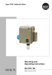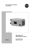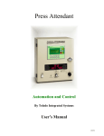
1
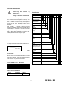
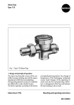
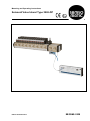
Mounting and Operating Instructions Solenoid Valve Island Type 3965-DP Edition: November 2013 EB 3965-2 EN Page Contents General instructions 3 Model number and device index Article code Serial number Current versions of hardware/firmware DP modules, GSD file Technical data 4 Electric connection module for PROFIBUS-DP (Ex ib[ia]) Input module for NAMUR sensors (Ex ia) Mounting 5 Type 3965-DP Solenoid Valve Island NAMUR input module 5 Pneumatic connection Type 3965-DP Solenoid Valve Island Electrical connection 6 Power supply PROFIBUS connection Connecting the NAMUR input modules Connecting NAMUR sensors 6 6 7 7 Data communication between master and slave 8 Setting the PROFIBUS-DP address Status indication on the connection module Status indication on NAMUR input module GSD file Device configuration and parameterization Process mapping (binary inputs and outputs) Start-up checklist 8 8 8 9 9 13 14 Troubleshooting 15 Servicing explosion-protected devices 17 Maintenance, calibration and work on equipment 17 Certification 18 -2- EB 3965-2 EN General instructions The devices may only be mounted, started up, and operated by experienced personnel familiar with this product. Proper shipping and appropriate storage of the device are assumed. Article code In these mounting and operating instructions, the term “experienced personnel“ refers to persons, who are able to evaluate the responsibilities assigned to them as well as recognize potential hazards due to their specialized training, knowledge, and experience as well as their special knowledge of the relevant standards. 3965-DPplus / 3965- . . Type of protection II 2 G Ex i/ II 2 D Ex tD A21 1 1 . . 3 1 . . . . . 0 | 1 1 | 6 . . . . . . . . . 0 0 0 Electrical connection PROFIBUS-DP (SV-Island 3965-DP) Nominal signal 6 V DC (solenoid valve) 1 Status indication Without LED (yellow) Staff handling or operating explosion-protected devices in hazardous areas must be specially trained or instructed, i.e. staff must be authorized to handle or operate explosion-protected devices. 0 3 Switching function 3/2-way 5/2-way 2/2-way Refer to Data Sheet T 3965 EN for technical data, ordering data, accessories and spare parts. 0 1 2 No. of switching functions 1 to 16 Base module (reserve) Without 1 to 7 Pneumatic connection module With pressure reducer, G With press. reducer, NPT Without press. reducer, G Without pr. reducer, NPT Model number and device index The model number and device index are written on the nameplate: 0 1 | 7 0 1 2 3 Manual override Without Pushbutton Switch Fig. 1 0 1 2 Ambient temperature Serial number –20 to +50 °C 0 Ext. NAMUR sensors Because three Ex certificates are valid for solenoid valve island 3965-DP, three type labels are placed at the device. The serial number as unique identification of the device is only printed to one of them. Without 0 Safety function Without 0 Special version Current HW/FW-Version: DP module DP module Power supply CPU NAMUR modul Without Hardware Firmware VN10-00 VN00-50 VN10-00 SR0x03 SR0x01 Aktuelle Version: GSD-Datei Version File name edited GSD_V1.1 39650A55.GSD 26.11.2012 -3- EB 3965-2 EN Technical data Electric connection module for PROFIBUS-DP (Ex ib[ia]) Version Explosion protection certification Electric connection module for PROFIBUS-DP (Ex ib[ia]) for use in hazardous areas; Controlling of 16 solenoid valves (6 V DC) with cable break monitoring; Connection of two input modules for 32 NAMUR sensors (Ex ia) with cable break and short-circuit monitoring PTB 09 ATEX 2032 (power supply unit) and PTB 09 ATEX 2033 (CPU) Module enclosure GD AlSi12, powder-coated, gray-beige RAL 1019 End plates GD AlSi12, anodized, black Material Gaskets Silicone rubber Screws 1.4571 Plug-type connector Polyamide 1 x LED (external communication DP): green = Connection OK; red = Connection interrupted Status indication 1 x LED (operation): green = ON; red = OFF < 100 ms (NAMUR sensors) Cycle time < 500 ms (solenoid valves) 24 V DC (+/–15 %) Power input ≤ 4.5 W; output rating ≤3.5 W Power supply Galvanic isolation between input circuit and output circuit; rated voltage: 60 V Power supply Two-wire connecting cable (wire cross-section 1.5 mm², flexible); 2 m length Connection PROFIBUS-DP Plug-type connector, 9-pole Input modules Round plug connector M12x1, 5-pole (max. two input modules can be connected) Transmission rate 9.6 kBit/s to 1.5 Mbit/s Bus address setting With two rotary code switches at the front (address range between 1 and 99) Degree of protection IP 40 Ambient temperature –20 to +50 °C Weight, approx. 750 g External RS-485 fieldbus network (RS485-IS according to PNO guidelines): - - Max. value per terminal pair: Ui = 4.2 V Max. value of terminal pair: Total Ii = 4.8 A Cables type A or B Comments according to EN 60079-25 with following data: L‘/R‘ <= 15µH/Ohm C‘ <= 250 nF/km Diameter of stranded wire >= 0.2 mm Concentrated inductance and capacitance in the external fieldbus are not permissible Compensating currents are prevented by shielding according to IEC 60079-4 Input module for NAMUR sensors (Ex ia) Version Input module for 16 NAMUR sensors (Ex ia) for use in hazardous areas Explosion protection certification PTB 09 ATEX 2033 System-internal current circuit, central supply by the power supply unit of the driver module Power supply Power input <= 500 mW Galvanic isolation to internal electronics and to supply current circuit According to EN 60947-5-6 (NAMUR), intrinsically safe according to EN 60079-11 Input circuits Open-circuit voltage: 8 V DC; short-circuit current: 6 mA; wire break <= 0.2 mA On/off switching threshold: typically 2.1 mA/1.2 mA Enclosure Aluminum, polyamide Material Front plate Printed circuit board FR 4, light gray, printed in black 1 x LED (operation); green: power supply ON 16 x LED (sensor state); green: NAMUR sensor unattenuated LED flashes in the event of failure: wire break 0.5 Hz/short circuit 2 Hz Snap-on mounting for top hat rail TH 35 according to EN 60715 Status indication Mounting Connection NAMUR sensors Terminals, detachable BUS INPUT/OUTPUT Round plug connector M12x1, 5-pole Degree of protection IP 20 Ambient temperature –20 to +50 °C Weight, approx. 380 g -4- EB 3965-2 EN Mounting Pneumatic connection Type 3965-DP Solenoid Valve Island Type 3965-DP Solenoid Valve Island See EB 3965 EN, page 8 See EB 3965 EN, pages 9 and 10 NAMUR input module A snap-on fixture is located on the bottom of the module which is used to attach the modules to a top-hat rail. Snap-on mounting for top hat rail TH 35 according to EN 60715 Fig. 2 -5- EB 3965-2 EN PROFIBUS connection Electrical connection As far as the electrical installation of the device is concerned, the relevant electrotechnical regulations and the accident prevention regulations of the country in which the device is used must be observed. In Germany these are the VDE regulations and the accident prevention regulations of the employers’ liability insurance association. For mounting in hazardous areas, the respective national regulations of the country in which the device is used applies. In Germany these are VDE 0165/EN 60079. For connection to certified intrinsically safe current circuits, the EC Type Examination Certificate PTB 09 ATEX 2032 and PTB 09 ATEX 2033 for Zone 1 or 21 applies (see pages 18 to 22). PROFIBUS cable Cable type A or B PROFIBUS connector (RS485-IS, intrinsically safe) When connected to DC voltage signals, correct polarity must be ensured. D-sub female connector for PROFIBUS-DP connection (see below for pin layout) Adhere to the terminal assignment! Switching the assignment of the electrical terminals may cause the explosion protection to become ineffective! Do not loosen enameled screws in or on the housing. D-sub female connector The maximum permissible values specified in the EC type examination certificate apply when interconnecting intrinsically safe electrical equipment (Ui or Uo; Ii or Io; Pi or Po; Ci or Co, and Li or Lo) (see pages 18 to 22). Power supply 24 V DC The power supply is connected at the power supply unit of the device using a 2 m cable with the type of protection Ex e (increased safety). Attach a grounding screw to the base plate of the power supply unit for the equipotential bonding required in hazardous areas (Fig. 3). brown blue D-sub male connector D-sub connector pin layout for RS485-IS Pin no. Pin layout of D-sub Meaning 1 2 n.c. n.c. 3 RxD/TxD-P 4 5 6 7 n.c. ISGND ISP n.c. 8 RxD/TxD-N 9 n.c. Not assigned Not assigned Receive/send data of noninverting line Not assigned Bus termination (minus) Bus termination (plus) Not assigned Receive/send data of inverting line Not assigned Fig. 4 Fig. 3 -6- EB 3965-2 EN The device must be connected to an intrinsically safe PROFIBUS-DP network (according to PNO User and Installation Guideline 2.262). If necessary, connect a DPEx-i segment coupler in front of the device. The bus network is connected using a 9-pole D-sub female connector (see Fig. 4). Only use a D-sub connector suitable for RS495-IS. Use a standard PROFIBUS cable (cable type A or B) according EN 50039 for the supply lines. The first module is connected to the base module using a connecting cable (max. 1.5 m, see below for accessories: 8831-0874). This module is connected to the Type 3965-DP at the M12 female connector intended for this purpose which is located above the Dsub female connector. It is connected to the NAMUR input module at the M12 female connector marked 'BUS INPUT'. To connect a further NAMUR input module (cascading), the BUS OUTPUT connection of the first module is connected to the BUS INPUT of the second module using a connecting cable (max. 0.3 m, see below for accessories: 8831-0873). During installation work, make sure that the PROFIBUS network is terminated at the first and last participant of the segment by a termination resistor. Resistance combinations are usually integrated into the bus connectors which can be activated for active termination. Fig. 6 Connecting the NAMUR input modules A maximum of two input modules may be connected to the Type 3965-DP solenoid valve island (see Fig. 6). These modules are connected to the driver module by an internal, intrinsically safe system bus (category ib). This internal bus is responsible for data communication as well as power supply of the NAMUR input modules. These modules do not require their own PROFIBUS-DP address since they are not directly connected to the PROFIBUS network. They are assigned to the corresponding driver module. M12 x1 female connector on driver module Accessories Order no. Input module for NAMUR sensors for 16 NAMUR sensors (Ex ia), IP 20 1170-3185 Connecting cable, with M12x1 round connector, 5 pole, on both sides: 0.3 m length 1.0 m length 8831-0873 8831-0874 Connecting NAMUR sensors M12 x1 female connectors NAMUR input module BUS INPUT Connecting cable max. 1.5 m BUS OUTPUT Connecting cable max. 0.3 m Fig. 7 The NAMUR sensors can be connected directly to the 4-pole terminal block (Combicon, blue) as shown in Fig. 7. Two sensors per terminal block can be connected. The maximum line length to connect sensors is 30 m. Fig. 5 -7- EB 3965-2 EN Status indication on NAMUR input module Data communication between master and slave Setting the PROFIBUS-DP address Power supply Sensor states, diagnosis Fig. 10 Fig. 8 Use the two rotary code switches on the connection module to set the PROFIBUS-DP address. Use switch 1 to set the first digit of the address and switch 2 for the second digit of the address. Range of code switch marking is from 0 to 9 (0, 1, 2, 3 as digits, others as bars in clockwise direction) The address range is between 01 and 99. The address of all PROFIBUS participants (regardless of whether master or slave) must be unique. Factory-provided preset of the address is“55”. The POWER LED indicates whether the power supply is connected to the NAMUR input module. Each sensor is assigned an LED to indicate the sensor state and the corresponding diagnosis. LED POWER Fig. 8 shows the bus address setting 32 Sensor state and diagnosis Status Description OFF Green OFF OFF Green continuously ON Green continuously ON Blinking green (0.5 Hz) Blinking green (2 Hz) Power supply switched off Power supply OK Not initialized PROFIBUS communication error PROFIBUS OK Wire break detected Short circuit detected Fig. 9 Status indication on the connection module The two LEDs on the connection module (Fig. 9) indicate whether the power supply is connected (I/O) and the communication status between master and slave. LED I/O DP Status OFF Green Blinking red: 0.5 Hz OFF Red Green Description Power supply switched off Power supply OK Malfunction of NAMUR sensor(s) Power supply switched off PROFIBUS communication error PROFIBUS OK -8- EB 3965-2 EN GSD file 3965-DP with one NAMUR input module: GSD files are readable ASCII text files and contain both general and device-specific specifications for communication. They describe the entire scope of configuration and the communication properties of a PROFIBUS participant. By means of keywords, a configuration tool device identification (ID number), the parameters, the corresponding data type permitted limit values for the configuration of from the GSD. reads the adjustable and the the device Properties, such as transmission rate, time behavior, configuration data, parameters, diagnostic data etc, are described in this file by the keywords. • 8 solenoid valve drivers (1x8) 8 sensor inputs (1x8) • 8 solenoid valve drivers (1x8) 16 sensor inputs (1x16 or 2x8) • 16 solenoid valve drivers (1x16 or 2x8) 8 sensor inputs (1x8) • 16 solenoid valve drivers (1x16) 16 sensor inputs (1x16 or 2x8) or 16 solenoid valve drivers (1x16 or 2x8 ) 16 sensor inputs (1x16) 3965-DP with two NAMUR input modules: • 8 solenoid valve drivers (1x8) 16 sensor inputs (1x8 + 1x8) • 8 solenoid valve drivers (1x8) 24 sensor inputs (1x16 + 1x8) • 8 solenoid valve drivers (1x8) 32 sensor inputs (1x16 + 1x16) • 16 solenoid valve drivers (1x16) 16 sensor inputs (1x8 + 1x8) or 16 solenoid valve drivers (2x8) 16 sensor inputs (1x16) • 16 solenoid valve drivers (1x16) 24 sensor inputs (1x16 + 1x8) • 16 solenoid valve drivers (1x16) 32 sensor inputs (1x16 + 1x16) Device configuration and parameterization The Type 3965-DP Solenoid Island Valve is connected to the PROFIBUS-DP networks as a slave. The device is configured and parameterized based on the associated GSD file. The solenoid valve drivers and sensor inputs can be configured in groups containing either 8 or 16 binary signals. Note that a maximum of three groups are permitted for more than 24 signals to be processed (sensor signals and drivers in total). Minimum configuration: • 8 solenoid valve drivers without diagnosis • At least one solenoid valve must be connected to prevent a configuration error from being displayed. The device is configured and parameterized using a suitable configuration tool. Refer to the user manual of the corresponding tool for more details. See page 10 to 12 for screenshots of various configuration tools (e.g. Siemens, Procentec, BihlWiedemann). Follow the following instructions to configure and parameterize the device: • Install the GSD file 39650A55.GSG (DE) or 39650A55.GSE (EN). (the maximum number of groups with 8 or 16 binary signals are written in parentheses) • Connect the Type 3965-DPplus slave(s) to the PROFIBUS-DP network and assign the slave address(es) within the range between 1 and 99. 3965-DP without NAMUR input modules: • Parameterize the Type 3965-DPplus slaves (number of drivers/binary outputs, number of NAMUR sensor signals/binary inputs) • Optional (provided the tool supports the function): Display fault alarms over PROFIBUS standard diagnostic function (parameterization in channel pairs). Device combinations: • 8 solenoid valve drivers (1x8) 0 sensor inputs • 16 solenoid valve drivers (1x16 or 2x8) 0 sensor inputs -9- EB 3965-2 EN Example: Siemens (STEP7) - 10 - EB 3965-2 EN - 11 - EB 3965-2 EN Example: Procentec (ProfiTrace2) - 12 - EB 3965-2 EN Example: Bihl+Wiedemann (PROFIBUS-DP-Master) - 13 - EB 3965-2 EN Coding of solenoid valve states Process mapping (binary outputs and inputs) Communication between the PROFIBUS-DP master and the Type 3965-DP solenoid valve island (PROFIBUS-DP slave) is performed cyclically based on DP-V0 protocol. The binary outputs (drive bits) and the binary inputs (NAMUR sensor states, diagnosis data) are transferred completely in each cycle. As a result, the drive bits in the Type 3965-DP are cyclically refreshed during active data transmission and the status and diagnosis data in the process control system (or PLC) are updated in the same cycle. The drive bits are configured as binary outputs in the I/O modules of the process control system (or PLC) and the input signals are configured correspondingly as binary inputs. In this way, they can be easily processed with default functions in the higher-level system. With the maximum configuration (16 solenoid valve drivers and 32 NAMUR sensor signals), the data volume is 12 bytes per PROFIBUS-DP slave. Other configurations have a correspondingly smaller data volume. The entire process mapping is represented below including the corresponding assignments of bits to the solenoid valves and NAMUR sensor inputs. Diagnosis bit NAMUR sensor input modules Binary inputs NAMUR sensor signals, status bits Assignment according to the ports of the NAMUR modules BYTE 3 Bit NAMUR input module 1, ports 1-8 8 7 6 5 4 7 6 5 4 3 16 7 Binary inputs Fig. 11 Binary outputs Solenoid valve drive bits BYTE 4 Bit BYTE 1 Bit X11 2 1 NAMUR input module 1, ports 1-8 15 14 13 12 11 10 6 5 4 3 2 1 1 0 9 0 NAMUR sensor signals, diagnosis bits 8 7 NAMUR input module 1, ports 9-16 7 6 5 4 3 2 6 5 4 3 2 1 1 0 16 7 NAMUR input module 1, ports 9-16 15 14 13 12 11 10 6 5 4 3 2 1 9 0 X10 MV8 MV7 MV6 MV5 MV4 MV3 MV2 MV1 7 6 5 4 3 2 1 0 X13 BYTE 5 Bit X12 MV16 MV15 MV14 MV13 MV12 MV11 MV10 MV9 7 6 5 4 3 2 1 0 Binary inputs Binary inputs 3 2 Assignment according to the ports of the NAMUR modules Assignment according to Fig. 11 BYTE 0 Bit Connection OK Wire break diagnosis Example 2: Solenoid valve 13 (connection X13/MV12): Wire break Binary outputs: Byte 1 / Bit 4 = Last switching state (1/0) Binary inputs: Byte 1 / Bit 4 = 1 Bit Type 3965-DP Solenoid Valve Island 0 1 Example 1: Solenoid valve 4 (connection X10/MV4): ON/Line OK Binary outputs: Byte 0 / Bit 3 = 1 Binary inputs: Byte 0 / Bit 3 = 0 BYTE 2 Solenoid valves 1 OFF (idle position/safe state) ON 0 Drive bits Assignment according to the ports of the NAMUR modules Solenoid valve diagnosis bits Assignment according to Fig. 11 BYTE 6 X11 Bit X10 BYTE 0 MV8 MV7 MV6 MV5 MV4 MV3 MV2 MV1 Bit 7 6 5 4 3 2 1 0 X13 NAMUR sensor signals, status bits BYTE 7 Bit X12 BYTE 1 MV16 MV15 MV14 MV13 MV12 MV11 MV10 MV9 Bit 7 6 5 4 3 2 1 0 - 14 - NAMUR input module 1, ports 1-8 8 7 6 5 4 3 7 6 5 4 3 2 16 7 2 1 1 0 NAMUR input module 1, ports 1-8 15 14 13 12 11 10 6 5 4 3 2 1 9 0 EB 3965-2 EN Binary inputs Start-up checklist NAMUR sensor signals, diagnosis bits Assignment according to the ports of the NAMUR modules 1. BYTE 8 Bit BYTE 9 Bit 8 7 NAMUR input module 1, ports 9-16 7 6 5 4 3 2 6 5 4 3 2 1 1 0 16 7 NAMUR input module 1, ports 9-16 15 14 13 12 11 10 6 5 4 3 2 1 9 0 Switch off power supply First check whether the cables are correctly connected. This must be performed with the power supply switched off: • • • Coding of NAMUR sensor states Status bit 0 1 0 1 Diagnosis bit 0 0 1 1 • • Attenuated; line OK Unattenuated; line OK Wire break diagnosis Short circuit diagnosis Power cable connected to 24 V DC? PROFIBUS cable connected at the D-sub female connector of the driver module? Bus terminators activated (in first or last slave in the segment)? Cable for NAMUR input modules connected? External solenoid valves connected correctly? 2. Switch on power supply, Master slave offline After checking the cables with the power switched off, switch on the power supply of 24 V DC. Check the status LEDs on the driver module and NAMUR modules to ensure they indicate the correct status: Example 3: NAMUR sensor, input module 1; sensor 6 Status: Attenuated/Line OK Binary input: Byte 2 / Bit 5 = 0 Binary input: Byte 4 / Bit 5 = 0 Example 4: NAMUR sensor, input module 2; sensor 13 Status: Unattenuated/Line OK Binary input: Byte 7 / Bit 4 = 1 Binary input: Byte 9 / Bit 4 = 0 Example 5: NAMUR sensor, input module 1; sensor 11 Status: Wire break Binary input: Byte 3 / Bit 2 = 0 Binary input: Byte 5 / Bit 2 = 1 • LEDs on the driver module • I/O: green (power supply connected) • DP: red (PROFIBUS offline) • LEDs on NAMUR modules • Power: green (power supply switched on) • Sensor inputs: all LEDs off (inputs are first initialized after the PROFIBUS has been connected) 3. Master slave online Example 6: NAMUR sensor, input module 2; sensor 7 Status: Short-circuit Binary input: Byte 6 / Bit 6 = 1 Binary input: Byte 8 / Bit 6 = 1 Check the communication between master and slave when they are online. Check the status LEDs on the driver module and NAMUR modules to ensure they indicate the correct status: - 15 - • LEDs on the driver module • I/O: green (power supply switched on) • DP: green (PROFIBUS online) • LEDs on the NAMUR modules • Power: green (power supply switched on) • Sensor inputs: current sensor states (attenuated/unattenuated) or wire break for all unoccupied connections (LED blinks, 0.5 Hz) EB 3965-2 EN Troubleshooting Type 3965-DPplus Valve Driver Module/PROFIBUS-DP slave Malfunction LED status I/O LED OFF Diagnosis (possible cause of malfunction) Interrupted power supply Possible causes Power supply unit of driver module defective DP LED OFF Recommended action Make sure that the power supply unit is working. If this is not the case, replace the unit. Connect mains cable of the power supply unit to 230 V AC supply. I/O LED green Power supply OK PROFIBUS-DP not active DP LED red Wiring faulty Connect mains cable of the driver module to the 24 V DC output terminals; Observe polarity (brown: +, blue: –)! PROFIBUS cable and/or connectors not correctly connected or defective Check that the cable is OK. If this is not the case, replace it. Check whether the connectors are wired correctly. Connect the bus termination resistor in the first and last device of the segment (see page 6, PROFIBUS connection) Fasten connector connection. I/O LED red (blinking) Communication to the NAMUR input module(s) interrupted DP LED green Power LED: OFF Master slave communication still offline (not started) Activate master slave communication from the master Configuration is invalid (master shows configuration error) Check entered configuration and correct (see page 10, Device configuration and parameterization) Baud rate setting incorrect Correct Baud rate setting (the same Baud rate must be set for all participants (master, slave and, if applicable, segment coupler). Address error Check master and/or slave address and correct, if necessary (see p. 9, Setting the PROFIBUS-DP address) Connecting cable and/or connector not connected or defective (master shows diagnosis error) Make sure that the cable and connector work properly. If this is not the case, replace them. Connect cable properly (see p. 7, Connecting the NAMUR input modules) Fasten connector connection. Communication to the NAMUR input module(s) interrupted Power LED: ON Connecting cable not connected properly; INPUT/OUTPUT connection wrong (master shows diagnosis error) Connect cable properly (see p. 7, Connecting the NAMUR input modules) Fasten connector connection. - 16 - EB 3965-2 EN NAMUR input module Malfunction LED status Diagnosis (possible cause of malfunction) Possible causes Recommended action POWER LED OFF Interrupted power supply to driver module Power supply unit of driver module defective Make sure that the power supply unit is working. If this is not the case, replace the unit. Sensor LEDs OFF POWER LED ON Sensor LEDs OFF Connect mains cable of the power supply unit to 230 V AC supply. Power supply driver module OK Processing of sensor signals switched off Wiring in driver module faulty Connect mains cable of the driver module to the 24 V DC output terminals; Observe polarity (brown: +, blue: –)! PROFIBUS connection not yet active (input modules are initialized first when the connection is activated for the first time) Activate master slave communication from the master Wiring in NAMUR signal modules faulty; BUS INPUT and BUS OUTPUT incorrectly connected with connecting cable Make sure that the output of the driver module is connected to BUS INPUT of the first NAMUR module and, if applicable, the BUS OUTPUT of the first module is connected with BUS INPUT of the second module. - 17 - EB 3965-2 EN Servicing explosion-protected devices If a part of the device on which the explosion protection is based needs to be serviced, the device must not be put back into operation until a qualified inspector has assessed it according to explosion protection requirements, has issued an inspection certificate or given the device a mark of conformity. Inspection by a qualified inspector is not required if the manufacturer performs a routine test on the device prior to putting it back into operation. The passing of the routine test must be documented by attaching a mark of conformity to the device. Maintenance, calibration and work on equipment The interconnection with intrinsically safe circuits to check or calibrate the apparatus must only be performed with intrinsically safe current/voltage calibrators and measuring instruments to rule out any damage to components relevant for explosion protection. The maximum values for intrinsically safe circuits specified in the approvals must be kept (see pages 19 to 22). Replace explosion-protected components only by original, routine-tested components from the manufacturer. Devices that have already been operated outside hazardous areas and are intended for future use inside hazardous areas must comply with the safety requirements placed on serviced devices. Before being used inside hazardous areas, test the devices according to the specifications for servicing explosionprotected devices. - 18 - EB 3965-2 EN Certification - 19 - EB 3965-2 EN - 20 - EB 3965-2 EN - 21 - EB 3965-2 EN - 22 - EB 3965-2 EN - 23 - EB 3965-2 EN - 24 - EB 3965-2 EN SAMSOMATIC GMBH A member of the SAMSON GROUP Weismüllerstraße 20 – 22 60314 Frankfurt am Main Germany Phone: +49 69 4009-0 Fax: +49 69 4009-1644 E-mail: [email protected] Internet: http:// www.samsomatic.de 2013-11 – EB 3965-2 EN Specifications subject to change without notice