1
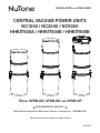
INSTALLATION AND USER GUIDE CENTRAL VACUUM POWER UNITS NC1000 / NC3000 / NC5000 HHKIT500A / HHKIT500E / HHKIT600E AB0039 MODEL SFDB-DN, SFDB-DO AND SFDB-DP ! FOR RESIDENTIAL USE ONLY BROAN-NUTONE CANADA ULC; MISSISSAUGA, ONTARIO ! WWW.NUTONE.CA 1-888-882-7626 REGISTER YOUR PRODUCT ONLINE AT: WWW.NUTONE.CA 30042506A IMPORTANT SAFETY INSTRUCTIONS SAVE THESE INSTRUCTIONS READ ALL INSTRUCTIONS BEFORE USING THIS APPLIANCE When using an electrical appliance, basic precautions should always be followed, including the following: WARNING CAUTION ! To reduce the risk of fire, electric shock or injury: 1. Do not put any object into openings. Do not use with any opening blocked; keep free of dust, lint, hair and anything that may reduce air flow. 1. Do not use on wet surfaces or outdoors. 2. Do not vacuum liquids or fine powders (such as drywall dust). 2. Ensure air flows freely and exhausts unobstructed from top or side outlet. 3. Do not use to pick up flammable or combustible liquids such as gasoline or use in areas where they may be present. 3. Do not use without filter (or filters, according to the model) in place. 4. Do not pick up anything that is burning or smoking, such as cigarettes, matches, or hot ashes. 4. Do not use to blow leaves or debris. 5. Do not allow to be used as a toy. Close attention is necessary when used by or near children. 5. Do not place any object on top of the unit. 6. Use only as described in this manual. Use only manufacturer's recommended attachments. 7. Do not use the pail as a wash bucket. 6. Do not install the unit horizontally. 7. Keep hair, loose clothing, fingers and all parts of body away from openings and moving parts. 8. Do not use the pail as a stool. 8. Turn off all controls before unplugging. 10. This appliance is for use on a standard 120 VAC, dedicated 15-amp branch circuit. 9. Avoid picking up sharp objects. 9. Use extra care when cleaning on stairs. 11. Do not unplug the unit by pulling on cord. To unplug, grasp the plug, not the cord. 10. Do not handle plug or appliance with wet hands. 11. Do not use with damaged cord or plug. If appliance is not working as it should, if it has been dropped, damaged, left outdoors, or dropped into water, return it to a Service Center. 12. Store your vacuum cleaner indoors in a clean, dry area, and away from extreme temperatures. 12. Keep your work area well lighted. 13. Any servicing other than that recommended in this manual should be performed by an authorized service facility. 13. Connect to a properly grounded outlet only. See grounding instructions shown on page 11. 14. We recommend that your unit be inspected by a specialized technician once a year. 14. When performing installation, servicing or cleaning the unit, it is recommended to wear safety glasses and gloves. 15. When applicable local regulations comprise more restrictive installation and/or certification requirements, the aforementioned requirements prevail on those of this document and the installer agrees to conform to these at his own expenses. 2 TABLE OF CONTENTS GENERAL INFORMATION . . . . . . . . . . . . . . . . . . . . . . . . . . . . . . . . . . 4 TOOL LISTING . . . . . . . . . . . . . . . . . . . . . . . . . . . . . . . . . . . . . . . . . . . . . . . . . . . 4 WORKING WITH PLASTIC TUBING. . . . . . . . . . . . . . . . . . . . . . . . . . . . . . . . . . . . . . . . . . . 4 WALL INLET INSTALLATION . . . . . . . . . . . . . . . . . . . . . . . . . . . . . . . . . 4 V600W VACUSWEEP® INLET VALVE INSTALLATION . . . . . . . . . . . . . . . . . . 5-7 CONNECTION FROM BELOW . . . . . . . . . . . . . . . . . . . . . . . . . . . . . . . . . . . . . . . . . . . . . 5 CONNECTION FROM BEHIND . . . . . . . . . . . . . . . . . . . . . . . . . . . . . . . . . . . . . . . . . . . . . 6 CONNECTION IN A WALL . . . . . . . . . . . . . . . . . . . . . . . . . . . . . . . . . . . . . . . . . . . . . . 7 POWER UNIT INSTALLATION . . . . . . . . . . . . . . . . . . . . . . . . . . . . . . . 8-10 LOCATING THE POWER UNIT . . . . . . . . . . . . . . . . . . . . . . . . . . . . . . . . . . CHANGING INTAKE LINE DIRECTION . . . . . . . . . . . . . . . . . . . . . . . . . . . . . . . CONVERTING POWER UNIT FROM CYCLONIC OPERATION TO A BAGGED SYSTEM (DEBRIS BAG INCLUDED) MOUNTING THE POWER UNIT . . . . . . . . . . . . . . . . . . . . . . . . . . . . . . . . . . FITTING MAIN LINE TO POWER UNIT . . . . . . . . . . . . . . . . . . . . . . . . . . . . . . . . . . . . . . . . . . . . . . . . . . . . . . . . . . . . . . . . . . . . . . . . . 8 . . 8 . . 9 . 9-10 . . 10 GROUNDING INSTRUCTIONS . . . . . . . . . . . . . . . . . . . . . . . . . . . . . . . . 11 WIRING . . . . . . . . . . . . . . . . . . . . . . . . . . . . . . . . . . . . . . . . . . . . . . . . . . . . . . 11 OPERATION AND MAINTENANCE . . . . . . . . . . . . . . . . . . . . . . . . . . . . 11-12 WHEN TO CHANGE BAG OR EMPTY DEBRIS PAIL . . . . . . . . . . . . . . . . . . . . . . . . . . . . . . HOW TO EMPTY DEBRIS PAIL (NC3000, NC5000 AND HHKIT600E POWER UNITS ONLY, IF NO BAG IS USED) DISPOSABLE BAG REPLACEMENT . . . . . . . . . . . . . . . . . . . . . . . . . . . . . . . . . . . . . PERMANENT FILTER (NC3000, NC5000 AND HHKIT600E POWER UNITS ONLY). . . . . . . . . . . . . . . REMOVAL AND INSTALLATION OF PERMANENT FILTER (NC3000, NC5000 AND HHKIT600E POWER UNITS ONLY) MOTOR FOAM FILTER (ALL UNITS) . . . . . . . . . . . . . . . . . . . . . . . . . . . . . . . . . . . . . . . . . . . . . . . . . . . . . . . . . . . . . . 11 . 11 . 12 . 12 . 12 . 12 ACCESSORY KITS . . . . . . . . . . . . . . . . . . . . . . . . . . . . . . . . . . . . 13-14 NCKIT1000 ACCESSORIES . . . . . . . . . NCKIT3000 ACCESSORIES . . . . . . . . . NCKIT5000 ACCESSORIES . . . . . . . . . HHKIT500A ACCESSORIES . . . . . . . . . HHKIT500E AND HHKIT600E ACCESSORIES . . . . . . . . . . . . . . . . . . . . . . . . . . . . . . . . . . . . . . . . . . . . . . . . . . . . . . . . . . . . . . . . . . . . . . . . . . . . . . . . . . . . . . . . . . . . . . . . . . . . . . . . . . . . . . . . . . . . . . . . . . . . . . . . . . . . . . . . . . . . . . . . . . . . . . . . . . . . . . . . . . . . . . . . . . . 13 . 13 . 13 . 14 . 14 ACCESSORIES . . . . . . . . . . . . . . . . . . . . . . . . . . . . . . . . . . . . . . . . 15 INSTALLING HOSE HANGER . . . . . . . . . . . . INSTALLING WAND HANGER (APPLICABLE KITS ONLY) CONNECTING HOSE . . . . . . . . . . . . . . . OPERATING HANDLE SWITCH . . . . . . . . . . . . . . . . . . . . . . . . . . . . . . . . . . . . . . . . . . . . . . . . . . . . . . . . . . . . . . . . . . . . . . . . . . . . . . . . . . . . . . . . . . . . . . . . . . . . . . . . . . . . . . . . . . . . . . . . . . . . . . . . . . . . . . . . . . . . 15 . 15 . 15 . 15 POWER BRUSH (ELECTRIC KITS ONLY) . . . . . . . . . . . . . . . . . . . . . . . . 16-18 HOW TO ASSEMBLE POWER BRUSH/WAND/HANDLE HOW TO USE POWER BRUSH/WAND . . . . . . . MAINTAINING THE POWER BRUSH . . . . . . . . SERVICE INFORMATION . . . . . . . . . . . . . POWER BRUSH SERVICE PARTS . . . . . . . . . TROUBLESHOOTING GUIDE. SERVICE PARTS . . . . . . . WARRANTY . . . . . . . . . . NOTES . . . . . . . . . . . . . . . . . . . . . . . . . . . . . . . . . . . . . . . . . . . . . . . . . . . . . . . . . . . . . . . . . . . . . . . . . . . . . . . . . . . . . . . . 3 . . . . . . . . . . . . . . . . . . . . . . . . . . . . . . . . . . . . . . . . . . . . . . . . . . . . . . . . . . . . . . . . . . . . . . . . . . . . . . . . . . . . . . . . . . . . . . . . . . . . . . . . . . . . . . . . . . . . . . . . . . . . . . . . . . . . . . . . . . . . . . . . . . . . . . . . . . . . . . . . . . . . . . . . . . . . . . . . . . . . . . . . . . . . . . . . . . . . . . . . . . . . . . . . . . . . . . . 16 . 17 . 18 . 18 . 18 . 19 . 20 . 21 . 22 GENERAL INFORMATION WALL INLET INSTALLATION TOOL LISTING MAKING THE WALL INLET CUTOUT The wall inlet should be located 18” on-center from the floor and directly in line with the attic or basement inlet tubing hole previously drilled in the wall plate or header. The wall inlet cutout must be exactly 37∕8” high by 27∕8” wide. Depending on the installation, the use of the following tools may be required: Wire strippers, 1/4’’ and 1/2” drill bits, utility knife, putty knife, 2½’’ hole saw, keyhole saw, hammer, cold chisel, level, flashlight, drill, electrical tape, Phillips no. 2 screwdriver, wrench, hacksaw, tape measure, safety glasses. ATTACHING THE INLET MOUNTING PLATE (V144) Reach through the inlet hole and locate the inlet tubing. Pull the flexible tubing through the inlet hole and remove the low-voltage wiring from inside the tube. Power tools are recommended to make the installation proceed quickly. A mask and gloves should be worn when cutting ducting and using glue. Remove the nail flange from the inlet mounting plate (see illustration at right). Apply cement to both the inside of the flexible tubing and to the outside of the mounting plate’s tube ring. Insert the mounting plate’s tube ring in the flexible tubing and twisting the AR0040 pieces as you join them to spread the cement, and align the mounting plate in a vertical position. WORKING WITH PLASTIC TUBING CUTTING TUBING Measure the length of tube needed. Allow 5/8” of tubing for inserting into fittings and 1½” for placing into flexible tubing. Cut the plastic tubing with a hacksaw, ensuring that the cut is exactly square. Use wire cutters or tin snips to cut flexible tubing, 8” lengths of flexible tubing should not be cut. Use a small knife or steel wool to remove any burrs from the inside of the tube. Use a file to slightly bevel the outside of the tube so that it will easily slide into the fitting. Use steel wool or a light grained sandpaper to buff the surface of the tube which will be glued. Now, strip the ends of the two low-voltage wires, and then connect the wires to the screw terminals on the back of the inlet cover. When the wiring is complete, assemble the inlet cover to the tube guard and mounting plate. MAKING A JOINT Insert the tube into the fitting, aligning both parts as they will be installed. Mark the tube and the fitting to quickly realign the joint. COMPLETING THE INLET ASSEMBLY Apply cement in an inch-wide band to the outside of the tube. Insert the tube into the fitting with the alignment marks a quarter turn apart, and then quickly push and turn the fitting to align the marks and spread the cement. Allow 1 minute for the joint to dry. Once you have attached the mounting plate to the flexible tubing, pull the low-voltage wire through the top wiring hole in the mounting plate. AO0010 INLET AE0024A CEMENTING FLEXIBLE TUBING INSTALLING THE INLET (V111) Ensure the ends of the flexible tubing are even. When joining flexible tubing to plastic tubing or to an inlet mounting plate, apply cement to both the inside of the flexible tubing and the outside of the plastic tubing or mounting plate tubing ring. Twist both pieces while joining them to evenly spread the glue. Allow 5 minutes for the cement to set in flexible tubing. Place the inlet into the wall cutout (the inlet cover remains on the outside). Hold the inlet in place and gradually tighten down each screw a little bit at a time. SECURE WIRE TO TUBING The low-voltage power wiring is run along with the tubing. Use electrical tape to secure the wire to the tubing. Tape the wire approximately every 12" to 18". AO0011 4 AO0045 MOUNTING PLATE V600W VACUSWEEP® INLET VALVE INSTALLATION CONNECTION FROM BELOW Measure distance (X) between the kickplate face and the inside edge of the cabinet. Then add 2¾” to the measured distance. Refer to figure . Measure out the new distance (X + 2¾”) from the cabinet door, to the reference mark. CABINET (X) + (2¾”) REFERENCE CABINET MARK DOOR X 2¾” KICKPLATE SUBFLOOR JOIST Drill a small reference hole straight down through to the basement. Refer to figure . Locate the reference hole in the basement and verify that there are no obstructions within 2” of either side and 4” behind. REFERENCE MARK Cut a 2½” diameter hole from the basement up into the base of the counter using the reference hole as a center. Refer to figure . SUBFLOOR REFERENCE HOLE SEEN FROM BASEMENT JOIST Using the reference hole as a center, cut a 2 ³/8” H x 6 5/8” W rough opening in the kickplate face. Refer to figure . Glue the long socket of the tight elbow (part no. V382XS) onto a section of 2” central vacuum tube. Make the terminal connections to the V600W VacuSweep inlet valve by sliding the low-voltage wire into wire clips. Turn the power to the vacuum unit ON to test the connection. After successful completion of the test, turn power to the vacuum unit OFF. Wrap a piece of wire/ string around the pipe. Using the wire/string to temporarily hold the pipe and elbow in place, insert the V600W VacuSweep inlet valve into the cabinet base and elbow. DO NOT GLUE this connection (Designed for friction fit). Refer to figure . Remove the wire/string. With the door in an open position, secure the V600W VacuSweep inlet valve to the cabinet base using no. 6 screws. Refer to figure . Ensure that the spring on the electrical connector has 1/8” clearance to rough opening. Continue with remainder of central vacuum connections. CABINET 2½” DIA DRILL 2½” DIA HOLE CABINET USING THE REFERENCE HOLE DOOR AS CENTER REFERENCE HOLE 2½” DIA HOLE DO NOT GLUE THIS SHORT SOCKET CONNECTION END OF ELBOW JOIST CUT A 23/8” H X 65/8” W ROUGH OPENING USING THE REFERENCE HOLE AS CENTER GLUE THIS CONNECTION (LONG SOCKET/PIPE) WIRE/STRING VACUSWEEP® INLET VALVE 2” CENTRAL VAC PIPE TERMINAL CONNECTIONS VACUSWEEP® INLET VALVE ELBOW 2 X NO. 6 SCREWS DO NOT GLUE THIS CONNECTION GLUE THIS CONNECTION 2” CENTRAL VAC PIPE TERMINAL WIRES AD0045A 5 V600W VACUSWEEP® INLET VALVE INSTALLATION (CONT'D) CONNECTION FROM BEHIND Choose a location under the cabinet for the V600W VacuSweep inlet valve so that it can be connected to the central vacuum tube. Measure distance (X) between the kickplate face and the inside edge of the cabinet. Then, add 2¾” to the measured distance. Refer to figure . Measure out the new distance (X + 2¾”) from the cabinet door, to the reference mark. CABINET (X) + (2¾”) REFERENCE CABINET MARK DOOR X 2¾” KICKPLATE SUBFLOOR JOIST REFERENCE MARK SUBFLOOR REFERENCE HOLE Drill a small reference hole straight down through to the basement. Refer to figure . Locate the reference hole in the basement and verify that there are no obstructions. SEEN FROM BASEMENT JOIST CABINET CUT 8” ACCESS Using a reciprocating saw, cut an access hole in the floor under the cabinet and approximately 8” behind the location of the V600W VacuSweep inlet valve reference hole so that the V600W VacuSweep inlet valve can be connected to vacuum tube by reaching through the access hole. Refer to figure . 8” DOOR HOLE BEHIND REFERENCE HOLE REFERENCE HOLE 8” ACCESS HOLE Using the reference hole as a center, cut a 2 ³/8” H x 6 5/8” W rough opening in the kickplate face. Refer to figure . Insert a coupling (part no. V127) onto the rear of the housing. DO NOT GLUE this connection (Designed for friction fit). Refer to figure . Make the terminal connections to the V600W VacuSweep inlet valve by sliding the low-voltage wire into wire clips. Turn the power to the vacuum unit ON to test the connection. After successful completion of the test, turn power to the vacuum unit OFF. Insert the V600W VacuSweep inlet valve into the cabinet base and tube. CABINET 2” CENTRAL COUPLING JOIST VAC PIPE CUT A 23/8” H X 65/8” W ROUGH OPENING USING THE REFERENCE HOLE AS CENTER DO NOT GLUE THIS CONNECTION TERMINAL CONNECTIONS VACUSWEEP® INLET VALVE GLUE THIS CONNECTION (COUPLING/PIPE) VACUSWEEP® INLET VALVE 2 X NO. 6 THIS CONNECTION With the door in an open position, secure the V600W VacuSweep inlet valve to the cabinet base using no. 6 screws. Refer to figure . Ensure that the spring on the electrical connector has 1/8” clearance to rough opening. From the basement reach through the access hole and glue a section of 2” central vacuum tube to the coupling. Continue with remainder of central vacuum connections. 6 2” CENTRAL VAC PIPE SCREWS DO NOT GLUE AD0046A COUPLING GLUE THIS CONNECTION 8” ACCESS HOLE TERMINAL WIRES V600W VACUSWEEP® INLET VALVE INSTALLATION (CONT'D) CONNECTION IN A WALL Remove the baseboard and locate studs in the wall where V600W VacuSweep inlet valve will be installed. Locate a position where the inlet will be clear of vertical studs and have free access either up or down dependent on location of central vacuum connection to the rest of the system. Refer to figure . REMOVE BASEBOARD REFERENCE HOLE AS CENTER STUD STUD Holding the drill at a 45° angle and as close to the wall as possible, between located studs, drill a small reference hole through the floor and subfloor. Locate this reference hole from beneath and measure over approximately 1 7/8” to center of base plate of wall. Ensure you have 1½” clearance from any obstacles if connecting from below. Refer to figure . STUD POSITION BETWEEN STUDS CUT A 23/8” H X 65/8” W If installation is from below use a 2½” diameter hole saw to remove wood floor and base plate, sufficient to locate V600W VacuSweep inlet valve centered over the reference hole. Refer to figure . ROUGH OPENING Using the reference hole as a center, cut a 2 ³/8” H x 6 5/8” W rough opening in the wall and baseboard. Refer to figure . Glue the long socket of the tight elbow (part no.V382XS) onto a section of 2” central vacuum tube. Make the terminal connections to the V600W VacuSweep inlet valve by sliding the low-voltage wire into wire clips. Turn the power to the vacuum unit ON to test the connection. After successful completion of the test, turn power to the vacuum unit OFF. Wrap a piece of wire/string around the tubing. Using the wire/ string to temporarily hold the pipe and elbow in place, insert the V600W VacuSweep inlet valve into the opening at the base of the wall and elbow. DO NOT GLUE this connection (Designed for friction fit). Refer to figure . HOLE TO BASEMENT DO NOT GLUE THIS CONNECTION SHORT SOCKET END OF ELBOW GLUE THIS CONNECTION (LONG SOCKET/PIPE) REFERENCE HOLE AS CENTER VACUSWEEP® INLET VALVE TERMINAL CONNECTIONS 2 X NO. 6 SCREWS ELBOW WIRE/STRING GLUE THIS CONNECTION VACUSWEEP® INLET VALVE 2” CENTRAL VAC PIPE AD0047A 2” CENTRAL VAC PIPE TERMINAL WIRES Remove the wire/string. With the door in an open position, secure the V600W VacuSweep inlet valve to the wall using no. 6 screws. Refer to figure . Ensure that the spring on the electrical connector has 1/8” clearance to rough opening. Continue with remainder of central vacuum connections. 7 POWER UNIT INSTALLATION ! All units: Disassemble WARNING the intake elbow from the back of the unit using a 3/8” socket to remove its both retaining nuts and screws. Do not install outdoors. Before being hung, rest the unit on a leveled surface to prevent the unit to fall down. When performing installation, servicing or cleaning the unit, it is recommended to wear safety glasses and gloves. LOCATING THE POWER UNIT All units: Flip the intake elbow 180°, then reassemble it to the unit, taking care to keep its gasket at its original position. NOTE: Ensure the gasket is not folded in order to prevent lack of suction and noise. • Locate the power unit away from the general living area in an accessible location for cleaning and maintenance. • Locate the power unit within 6 feet of a grounded electrical outlet. The power unit requires a 120 VAC power source, dedicated 15-amp branch circuit. • Do not locate the power unit close to a source of extreme heat (i.e.: water heater) or in an area with a high ambient temperature (i.e.: attic, furnace room). • If the power unit is located in a closet or a small utility room, make sure the area is well-ventilated (e.g.: with door louvers). NC1000, HHKIT500A The intake line connects to the right side of the unit. However, it is possible to change this configuration; to connect the intake line to the left side of the unit, follow these steps: Remove debris pail from power unit by releasing both latches on sides of the unit, pulling them out and then pushing up. Detach the pail from unit. NC1000, HHKIT500A AND HHKIT500E ONLY NC1000, HHKIT500A AND HHKIT500E ONLY AD0078 NC1000, HHKIT500A and HHKIT500E only: Grasp the edges of the bag collar and pull down; the bag will slide off easily. Do not pull on the bag. Set aside the bag. NC1000, HHKIT500A and HHKIT500E only: Put back in place the bag by grasping the edges of its collar and insert over bag adapter. Be careful not to tear the bag. Ensure the collar is positioned between the taper ring and the bag stopper on the bag adapter. AO0078 and HHKIT500E only: Using a Phillips screwdriver no. 2, remove the screw tightening the bag adapter and intake elbow junction. Disassemble the bag adapter from the intake elbow and set aside with its screw and nut. AD0077 and HHKIT500E only: Reassemble the bag adapter to the intake elbow. Align triangle with small inclined stud, then tighten the junction using the screw and nut previously removed in . CHANGING INTAKE LINE DIRECTION NC1000, HHKIT500A AD0076 NC1000, HHKIT500A AND HHKIT500E ONLY NC1000, HHKIT500A AND HHKIT500E ONLY TAPER RING AO0080 All units: Put the debris pail back in its place. AD0075 8 BAG STOPPER POWER UNIT INSTALLATION CONVERTING POWER UNIT FROM MOUNTING THE POWER UNIT CYCLONIC OPERATION TO A Carefully remove debris pail from power unit. Make sure bag is properly installed in power unit (if need be). Remove the BAGGED SYSTEM (DEBRIS BAG installation kit and securely reinstall debris pail. INCLUDED) Refer to illustration below to maintain minimum walls and floor clearance dimensions. MINIMUM CLEARANCE DIMENSIONS The NC3000, NC5000 and HHKIT600E units are factory shipped ready for use in cyclonic mode, but due to their hybrid design, they can also be operated with a disposable bag (391C). The bag adapter (included with the unit) must be installed if the disposable bag will be used. Follow these steps: TOP VIEW 12” minimum Remove the pail from unit by releasing its both side latches, 12” minimum pulling them out and then pushing them up. Detach the pail from unit. Assemble the bag adapter to the intake elbow. Align triangle with small inclined stud. 12” minimum from ceiling AD0080 FRONT VIEW Tighten the junction using the screw and nut (included in parts bag). AD0081 Unfold the disposable bag and grasp its collar where 18” minimum above floor indicated. Insert over bag adapter. Be careful not to tear the bag. Ensure the collar is positioned between the taper ring and the bag stopper on the bag adapter (see illustration below). Put the pail back in its place. TAPER RING AD0039A Position and install the wall mounting bracket with the provided screws. Refer to illustration on next page for proper mounting dimensions. CAUTION Ensure to screw the wall mounting bracket directly to a wall stud for a solid installation. AO0085 BAG STOPPER 9 POWER UNIT INSTALLATION (CONT'D) MOUNTING THE POWER UNIT (CONT'D) FITTING MAIN LINE TO POWER UNIT Run house vacuum line up to the elbow behind the power unit. Insert the end of the line in the elbow opening and secure house vacuum line by hand tightening the screw and nut provided (see illustration below). DO NOT GLUE. C L 18 ¹/8” 18 ¹/8” 3/4” TYP. INTAKE LINE TYPICAL CONNECTION TO POWER UNIT UPPER MOUNTING HOLES SCREW AND NUT FROM PARTS BAG INTAKE LINE 45¼” MIN. HEIGHT LOWER MOUNTING 1” TYP. HOLES AJ0001 32 7/8” NOTE FOR NC5000 UNITS ONLY Ensure to connect the utility valve (included) to the intake line in the appropriate way, as shown below. AD0079A Use the provided mounting screws to secure the mounting UNIT LOCATION bracket on the wall through upper and lower mounting holes. Hang power unit onto wall mounting bracket. Ensure the back brackets of the power unit are engaged with corresponding wall bracket fingers (or top fingers and lower tab for NC1000, HHKIT500A and HHKIT500E models; see figure below). Pull the power unit down to secure. NC3000, NC5000 AND HHKIT600E INTAKE LINE INTAKE LINE AJ0002 Assemble exhaust tubing to exhaust outlet on top or top side of the unit, according to the power unit model. DO NOT GLUE. NOTE FOR NC5000 UNITS ONLY NC1000, HHKIT500A AND HHKIT500E If desired, the coupling or elbow used to connect the exhaust line to the top of the unit may be secured using two 5/8” included screws. See illustration at right. AJ0003 NOTE: Using flexible tubing will ease future top cap removal. Make sure all tubing connections are air tight. The exhaust should not be vented into a wall, ceiling or concealed space in the house. It is recommended to vent the vacuum exhaust air to the outdoors. Exterior vented exhaust line should end using Model V145 wall cap. AD0074 10 NOTE: For optimal indoor air quality, exhausting the power unit to the outdoors is recommended but is not required. GROUNDING INSTRUCTIONS ! OPERATION AND MAINTENANCE Open the wall inlet cover and insert the end of the hose into the inlet to turn on the vacuum. For non-switched hoses, inserting the hose automatically turns on the power unit; removing the hose shuts off the power unit. Some hoses have switches which can be used to activate power unit. Unless using the utility valve (NC5000 unit only) the ON/OFF switch located on the power unit needs to be kept in the OFF position. As you vacuum, dirt and dust are carried to the power unit where they remain in a bag or in the debris pail (according to the power unit model). Use the cleaning tools as you would for any other vacuum cleaner. Avoid picking up very large debris or lengthy as these kinds of objects may become lodged in the hose or tubing. WARNING Improper connection of the equipment-grounding conductor can result in a risk of electric shock. Check with a qualified electrician or service person if you are in doubt as to whether the outlet is properly grounded. Do not modify the plug provided with the appliance – if it will not fit the outlet, have a proper outlet installed by a qualified electrician. Grounding Instructions – This appliance must be grounded. If it should malfunction or break down, grounding provides a path of least resistance for electric current, to reduce the risk of electric shock. This appliance is equipped with a cord having an equipment-grounding conductor and grounding plug. The plug must be plugged into an appropriate outlet that is properly installed and grounded in accordance with all local codes and ordinances. WHEN TO CHANGE BAG OR EMPTY DEBRIS PAIL WIRING With a 6 U.S. gallons (22.7 liters) capacity, under normal conditions the bag/debris pail requires changing/emptying approximately twice a year. If the bag/debris pail is full, you will notice a reduced suction from the system. Unless this loss of suction is caused by a blockage in the system, changing the bag or emptying the debris pail will solve the problem. This appliance is for use on a standard 120 VAC, dedicated 15-amp branch circuit with a NEMA 5-15R receptacle. Make sure that the power unit is connected to an outlet and has a grounding attachment plug that looks like the plug shown in illustration below. No adapter should be used with this power unit. NOTE: Even if not filled to capacity, if the bag seems tightly stretched when removing the debris pail, changing the bag will prevent it from tearing. CRIMP CONNECTORS TO HOW TO EMPTY DEBRIS PAIL (NC3000, NC5000 AND HHKIT600E POWER UNITS ONLY, IF NO BAG IS USED) BE CONNECTED IN LOW VOLTAGE TABS GROUNDED OUTLETS To empty the debris pail, release both latches on sides of the unit by pulling out and then pushing up. Holding the pail by the latches, lower it from unit. Carry pail to trash receptacle and dispose of debris. Put the pail back in its place. INLET LEADS MODEL V133 (22/2) GROUNDING PIN LOW VOLTAGE WIRE TO OTHER INLETS AE0044 INLET INLET INLET NOTE: Inlet leads to be connected to power unit low voltage tabs using crimp connectors (included in parts bag) and low voltage harness. 11 OPERATION AND MAINTENANCE (CONT'D) DISPOSABLE BAG REPLACEMENT Squeeze the filter in order To remove the disposable bag, release both latches on to move it past the inlet opening (B) Let the filter bear against the unit wall by releasing the pressure. Make sure to place the rigid ring in its groove to ensure proper sealing. sides of the unit by pulling out and then pushing up. Remove the pail from unit. Grasp the edges of the bag collar and pull down. The bag will slide off easily. Do not pull on the bag. Unfold the new bag. Grasp collar where indicated on the new bag and insert over bag adapter. Be careful not to tear the bag. Ensure the collar is positioned between the taper ring and the bag stopper on the bag adapter (see illustration below). Put the pail back in its place. B AD0085 NOTE: Make sure the filter is installed so that the pull tab (A) is accessible A for future filter removal. TAPER RING AA0005 CAUTION Be sure to reinstall filter properly. Appropriate location is critical to insure proper protection of the motor. MOTOR FOAM FILTER (ALL UNITS) AO0081 BAG STOPPER A motor foam safety filter, located at the top of the vacuum chamber provides protection against dirt being pulled into the motor if the disposable bag or permanent filter should accidentally be torn. This filter should be checked and cleaned if necessary when replacement bag is installed, or when permanent filter is removed (NC3000, NC5000 and HHKIT600E units only). Simply brush filter clean. If the filter is excessively soiled, hand wash in a water and mild detergent solution, rinse and let it dry completely on a flat surface before reinstalling. PERMANENT FILTER (NC3000, NC5000 AND HHKIT600E POWER UNITS ONLY) This filter protects the motor and stops small particles from escaping to the outside of the power unit wihout the need to replace it. The filter cleans itself by moving up when the power unit starts, and dropping down when the unit is turned off. Under normal use, there is no need to maintenance this filter. It is possible to remove it to inspect the motor foam filter, or to replace it if ever it has been damaged (by sharp debris, for example). CAUTION Operating the power unit without the motor foam filter will void the warranty. REMOVAL AND INSTALLATION OF REMOVING PERMANENT FILTER (NC3000, MOTOR FOAM NC5000 AND HHKIT600E POWER FILTER Remove the debris UNITS ONLY) pail and disposable bag or permanent filter. Lift the center of the wire retaining the motor foam filter and slide the filter out of its location. Remove the pail from unit. To remove the permanent filter, use pull tab (A) located on edge of filter to pull and loosen filter from inlet chamber wall. Squeeze from both sides of the filter to the center of the housing. Then, carefully remove it from the unit. A REINSTALLING MOTOR FOAM FILTER AD0084 To reinstall the motor foam filter, reverse the steps described above. AD0086 12 ACCESSORY KITS One of the following kits will be included depending on the power unit model: NCKIT1000 ACCESSORIES NCKIT3000 ACCESSORIES B Standard floor brush B Deluxe floor combo tool C Standard hose, 30 ft. long C Deluxe floor brush D Hose hanger D Mesh storage bag E Telescopic wand for static tools E Low-voltage hose, 30 ft. long F Round dusting brush F Hose sock G Upholstery tool G Hose hanger H Long crevice tool H Telescopic wand for static tools I Wand hanger J Round dusting brush B K Upholstery tool L Long crevice tool D C B E C D G H E H F F G L I AA0020 J K AA0021 B C NCKIT5000 ACCESSORIES B Power brush C Turn and clean floor brush D D Mesh storage bag F G E Dual-voltage hose, 30 ft. long F Hose sock E G Hose hanger H Telescopic wand for static tools I Wand for power brush J Wand hanger M K Round dusting brush J L Upholstery tool M Long crevice tool AA0022 13 K L H I ACCESSORY KITS (CONT'D) HHKIT500A ACCESSORIES HHKIT500E AND HHKIT600E ACCESSORIES B BN160 Combo floor brush B Power brush C Standard floor brush C BN160 Combo floor brush D Mesh storage bag D Mesh storage bag E Low-voltage hose, 30 ft. long E Dual-voltage hose, 30 ft. long F Hose hanger F Hose hanger G Telescopic wand for static tools G Telescopic wand for static tools H Round dusting brush H Wand for power brush I Upholstery tool I Round dusting brush J Long crevice tool J Upholstery tool K Orange garage hose, 35 ft. long K Long crevice tool L Standard floor brush B M Orange garage hose, 35 ft. long C B D E F C G E D F J H K I I J K L AA0029 AA0030 14 M G H ACCESSORIES INSTALLING HOSE HANGER CONNECTING HOSE SCREWS Secure the hose hanger to the LOW VOLTAGE HOSE (NCKIT3000 AND HHKIT500A ONLY) wall using 2 provided screws. According to the place chosen, the use of wall anchors (not included) may be necessary. A To ensure proper operation of the hose, insert hose into wall inlet (as shown beside). Align tab up with depression in wall inlet (A). AA0023 Wind hose around its hanger when not in use. AO0022 DUAL VOLTAGE HOSE (ELECTRIC KITS ONLY) AA0024 A INSTALLING WAND HANGER (APPLICABLE KITS ONLY) In addition to connecting into wall inlet (A), dual voltage hose must also be connected to a standard electrical outlet (B). B SCREW Secure the wand hanger to the wall using 2 screws (included). According to the place chosen, the use of wall anchors (not included) may be necessary. AO0023 OPERATING HANDLE SWITCH SCREW AA0025 LOW VOLTAGE HOSE The switch will turn power unit ON (I position) and OFF (O position). AA0027 Push the wand in its hanger DUAL VOLTAGE HOSE when not in use. Switch on II position: Central vacuum mode with power brush. Switch on I position: Central vacuum mode without power brush. AA0026 Switch on O (center) position: Power unit is turned OFF. 15 AA0028 POWER BRUSH (ELECTRIC KITS ONLY) HOW TO ASSEMBLE POWER BRUSH/WAND/HANDLE HOSE HANDLE Read important safety instructions before installing power brush. Ensure hose is disconnected from power supply before installing power brush. LOCK BUTTON Push wand into power brush neck so that the lock button snaps in place. RECEPTACLE PRONGS Connect hose handle into wand quick connector and QUICK CONNECTOR ensure that the prongs are aligned with the receptacle holes. Push until lock button snaps in place. CAUTION Always check underside of product for any obstructions prior to use. ! WAND WARNING Never leave electric power brush unattended while it is plugged in. WAND GRIP WAND TO POWER BRUSH CONNECTION LOCK BUTTON POWER BRUSH NECK HEIGHT ADJUSTMENT PEDAL WAND RELEASE PEDAL POWER BRUSH NECK RELEASE PEDAL LOCK BUTTON POWER BRUSH AO0078 AO0019 HOSE HANDLE TO WAND CONNECTION HOSE HANDLE LOCK BUTTON RECEPTACLE PRONGS HOSE HANDLE RELEASE BUTTON WAND AO0021 16 POWER BRUSH (ELECTRIC KITS ONLY) (CONT'D) EDGE CLEANER HOW TO USE POWER BRUSH/WAND Brush extends full width for effective edge cleaning along both sides of nozzle. To operate, simply run cleaner along edge board. Rubber bumper protects furniture and baseboards. CAUTION Always pick up hard or sharp objects by hand before using your power brush. Items such as pins, hairpins, tacks, crayons, etc., may damage the brush roll or may break the belt. ELECTRONIC CIRCUIT BREAKER The power brush is equipped with an electronic circuit breaker that protects the motor and the belt if a too large object is picked up accidentally. If the power brush stops while vacuuming, turn the power unit off using handle. Release the power brush from the wand and turn it over to see if there is an obstruction. When brush roll jam has been cleared, press the reset button (H) and AD0030 H connect the power brush back to the wand. Finally, turn the power unit/power brush back on. If it fails to restart or continues to trip without any apparent reason, the power brush must be serviced by an authorized service center. WAND RELEASE The power brush is not recommended for use on bare floors. Wand release pedal (A) on power brush allows you to quickly disconnect wand and switch to combination floor/rug tool for use on bare floors. A C B AO0020 CAUTION CLEANING AND STORAGE Always unlock brush neck before use. ! WARNING Disconnect electrical supply before servicing or cleaning the unit. Failure to do so can result in electrical shock or personal injury from cleaner suddenly starting. POWER BRUSH NECK RELEASE Push down power brush neck release pedal (B) to unlock brush neck. Return the neck to the upright position for storage. POWER BRUSH HEIGHT ADJUSTMENT BRUSH ROLL The icons (D) refer to the carpet pile height. Select height by depressing height adjustment pedal (C) to desired position: (Extra-Low), (Low), (Medium) or (High). In order to keep high cleaning efficiency and to prevent damage to your vacuum cleaner, the brush roll must be cleaned every time the belt is changed. The brush roll must also be cleaned according to the following schedule: FLOOR HEIGHT HEIGHT ADJUSTMENT LED INDICATORS The LEDs show the carpet pile covered by the selected height, e.g.: when (High) is selected, all LEDs will be lit, since AD0022 this height covers all pile heights. So if (Extra-Low) is selected, only the lowest LED will be lit. D VACCUM CLEANER USE CLEAN BRUSH ROLL Heavy (used daily) Every week Moderate (2-3 times per week) Every month Light (once a week) Every 2 months Check and remove hair, string and lint build-up frequently in the brush roll and end cap areas. Remove any dirt or debris in the belt path and in the brush roll areas. WAND LENGTH ADJUSTMENT HOUSING To keep the power brush housing clean, it can be wiped with a damp cloth and a mild soap solution, then thoroughly dried. Never use any type of chemical as they can damage the housing. E Extend (E) or shorten (F) the wand to comfortable work position by holding the wand grip (G) in one hand and sliding the upper section (the one with the prongs) with the other hand. STORAGE F G AD0024 AD0023 17 Ensure that hose and power cord are disconnected from wall inlet before unplugging power brush. Disconnect hose handle from wand. Always keep hose neatly coiled when not in use. When not in use, the power brush should be stored in a clean, dry place. POWER BRUSH (ELECTRIC KITS ONLY) (CONT'D) HOW TO CHANGE BRUSH ROLL MAINTAINING THE POWER BRUSH ! Replace brush roll when brush roll brissles are worn to the base support bars level. Turn power brush over and using a Phillips no. 2 screwdriver, remove the 3 brush roll cover retaining screws (FIG. 1) and set aside. Remove brush roll cover (FIG. 2). To free brush roll from base, start by sliding the belt side end and pull brush roll sideways (1). Once disengaged from housing, lift brush roll (2) out of its compartment (FIG. 3). Disengage brush roll from belt. Discard worn brush roll. Insert new brush roll through belt until belt is seated in its place. Push down brush roll back in place. Finalise the installation by reversing steps to . WARNING Disconnect electrical supply before servicing or cleaning the unit. Failure to do so can result in electrical shock or personal injury from cleaner suddenly starting. HOW TO CHANGE BELT ! WARNING Motor shaft can become hot during normal use. To prevent burns, avoid touching the motor shaft when replacing the drive belt. RETAINING SCREWS FIG. 1 Turn power brush over and using a Phillips no. 2 screwdriver, remove the 3 brush roll cover retaining screws (FIG. 1) and set aside. SERVICE INFORMATION To avoid unnecessary service calls, check the belt and brush roll often. Replace the belt if it is stretched or cracked. Clean the brush roll bristles when they are wrapped with thread and hairs. Build-up could cause the brush to rotate unevenly. AB0010 The model number and serial number are indicated on the rating label located underneath the power brush. Always refer to these numbers when inquiring about service. FIG. 2 NOTE: The motor is permanently lubricated and sealed. Do not oil the motor at any time. Remove brush roll cover (FIG. 2). AB0011 BELT To free brush roll from FIG. 3 base, start by sliding the belt side end and pull 2 brush roll sideways (1). Once disengaged from housing, lift brush roll (2) 1 out of its compartment (FIG. 3). AB0012 BRUSH ROLL POWER BRUSH SERVICE PARTS 3 1 4 2 2 5 AA0002 Disengage brush roll from worn belt and extract I the belt from motor shaft by a twisting motion in the enlarge area (I) specifically made for that purpose AB0013 (FIG. 4). Install new belt by reversing steps to . NOTE: To ease belt replacement, start by inserting one end around the motor shaft in the enlarged area (I). Insert brush roll through belt until belt is seated in its place. Push down brush roll back in place. FIG. 4 KEY NO. PART NO. DESCRIPTION 1 09234 Belt 2 09233 Brush Roll 3 09236 Brush Roll Cover with Screws 4 09235 Wand Release Pedal 5 18651 Wand Order Service Parts by “Part No.”, not by “Key No.” 18 TROUBLESHOOTING GUIDE PROBLEMS POSSIBLE CAUSES POSSIBLE REMEDY 1. Loss or decrease of • Debris pail or disposable bag is completely full. suction occurs. • Debris pail gasket damaged or missing. • Obstruction in the hose. A blockage in the hose can be determined by inserting the hose into any wall inlet and, while power unit is running, check each additional inlet for normal suction by holding the palm of your hand over the open inlet. If normal suction is felt at all other inlets, insert the hose into a second inlet. If the blockage still exists it is located in the hose. However, if the blockage does not occur when the hose is changed, the blockage is probably located in the tubing system leading to the original inlet. • Obstruction in the tubing system inside the walls. • Permanent filter or disposable bag torn. • Wall inlet cover not properly sealed. • Exhaust tubing or vent clogged. • Empty debris pail or change the disposable bag as described on pages 11 and 12. • Replace the debris pail gasket. • Disconnect the hose from the wall inlet and insert a blunt instrument into the hose — slightly smaller in diameter — such as a flexible garden hose. Push the garden hose through the cleaning system hose until the obstruction has been cleared. • Insert hose end into any inlet to make power unit running, then place the palm of your hand over the opposite end of the hose. When you can feel the suction increase, hold your hand over the hose end for a few seconds and then quickly remove your hand. This procedure repeated several times should clear the obstruction. If the blockage is not cleared, contact your nearest Service Center. • Clean the interior or the unit and install a new permanent filter (or disposable bag). • Check all wall inlet covers to be sure they are closed and sealed tightly. • Inspect and remove any blockages. • Replace defective wall inlet. 2. Power unit does • Defective inlet. Check other wall inlets. not start, or stops suddenly. on the • Power unit internal circuit breaker has been • Push RESET circuit breaker activated (the reset button is popped up). reset button BUTTON located on the left side of the power unit. If this button pops up again, contact your authorized Service Center. POWER SWITCH AC0003 • Blown fuse or tripped circuit breaker on house • Replace fuse or reset circuit breaker on house electrical panel. electrical panel. • Replace hose as required. • Defective hose. • Power unit overcurrent protector has been • Unplug the power unit, wait at least 15 minutes and plug back the power unit. activated. 3. Power unit runs • The unit power switch is in ON position. • Set the unit power switch to OFF position. continuously when • An electrical short has occurred somewhere in • Perform a complete check of all wall inlets and the hose is removed. the system. power unit low voltage control lead connections. Contact your authorized Service Center. 19 SERVICE PARTS 1 NC5000 UNIT 1 NC1000, NC3000 HHKIT500A, HHKIT500E AND HHKIT600E UNITS 2 12 11 9 10 3 8 REPLACEMENT PARTS AND REPAIRS In order to ensure your unit remains in good working condition, you must use Broan-NuTone genuine replacement parts only. Broan-NuTone genuine replacement parts are specially designed for each unit and are manufactured to comply with all the applicable certification standards and maintain a high standard of safety. Any third party replacement part used may cause serious damage and drastically reduce the performance level of your unit, which will result in premature failing. Broan-NuTone also recommends to contact a Broan-NuTone certified service depot for all replacement parts and repairs. 4 5 7 6 AL0011 KEY NO. 1 PART NO. NC1000 NC3000 HHKIT500A HHKIT600E HHKIT500E DESCRIPTION S10941396 NC5000 TOP CAP ASSEMBLY (INCLUDING ITEM 4) (UPPER PART) S10941411 NC1000, NC3000, HHKIT500A, HHKIT500E & HHKIT600E TOP CAP ASSEMBLY NC5000 1 1 1 2 S10941413 NC5000 TOP CAP ASSEMBLY (INCLUDING ITEM 4) (LOWER PART) 3 S10941399 MOTOR FOAM FILTER WITH FASTENER 1 1 1 4 S10941400 GASKET 1 1 3 5 S10941401 PERMANENT FILTER 1 1 6 S99670648 DEBRIS PAIL (INCLUDING KEY NO. 7) 1 1 1 7 S10941199 LATCH AND SCREWS 2 2 2 8 S10941404 LATCH KEEPER WITH SCREWS 2 2 2 9 S10941405 BAG ADAPTER WITH NUT AND SCREW 1 1 1 10 S10941408 UTILITY VALVE 1 1 11 S10941406 INTAKE ELBOW WITH GASKET, SCREWS, AND NUTS 1 1 1 12 S30390555 UNIT SUPPORT BRACKET 1 1 1 13 391C DISPOSABLE BAG (SET OF 3, NOT SHOWN) 1 1 1 NOTE: Order service parts by “Part No.” — not by “Key No.” 20 WARRANTY NUTONE MODELS NC1000, NC3000, NC5000, HHKIT500A, HHKIT500E AND HHKIT600E BROAN-NUTONE CANADA ULC CENTRAL VACUUM POWER UNIT LIMITED WARRANTY Broan-NuTone Canada warrants to the original consumer purchaser that its central vacuum power unit will be free from defects in materials and workmanship for five (5) years for NC1000, HHKIT500A and HHKIT 500E units, eight (8) years for NC3000 and HHKIT600E units and ten (10) years for NC5000 units. The first year of this warranty covers the parts and labor in an authorized service center. After the first year, the parts only will be covered under this warranty.THERE ARE NO OTHER WARRANTIES, EXPRESSED OR IMPLIED, INCLUDING, BUT NOT LIMITED TO, IMPLIED WARRANTIES OF MERCHANTABILITY OR FITNESS FOR A PARTICULAR PURPOSE. During these time periods, Broan-NuTone Canada will, at its option, repair or replace the power unit or part without charge, which is found to be defective under normal use and service. THIS WARRANTY DOES NOT APPLY TO THE INSTALLATION OR THE PARTS USED IN THE INSTALLED TUBING SYSTEM. All central vacuum hoses, electric or air-driven brushes, filters, attachments and accessories are warranted for one (1) year from the original purchase date with the exception to consumables such as light bulbs and belts. We invite you to register your product on line at www.nutone.ca. Broan-NuTone Canada reserves the right to limit this warranty if the product is not registered. This warranty does not cover (a) normal maintenance and service or (b) any products or parts which have been subject to misuse, negligence, accident, improper maintenance or repair (other than by Broan-NuTone Canada or an authorized representative), faulty installation or installation contrary to recommended installation instructions. The duration of any implied warranty is limited to the period as specified for the express warranty. BROAN-NUTONE CANADA’S OBLIGATION TO REPAIR OR REPLACE, AT BROAN-NUTONE CANADA’S OPTION, SHALL BE THE PURCHASER'S SOLE AND EXCLUSIVE REMEDY UNDER THIS WARRANTY. BROAN-NUTONE CANADA SHALL NOT BE LIABLE FOR INCIDENTAL, CONSEQUENTIAL OR SPECIAL DAMAGES ARISING OUT OF OR IN CONNECTION WITH PRODUCT USE OR PERFORMANCE. Please do not return your unit to place of purchase. Please visit www.nutone.ca for your closest service center. You may also call 1-888-882-7626 for the name of an authorized representative in your area. This warranty supersedes all prior warranties. Warranty service is to be completed by an authorized Service Center designated by Broan-NuTone Canada. Where applicable, in home service will be made available only in areas where a contracted service provider offers service (during the first year only). If in home service is not available, the product will be repaired or replaced, at Broan-NuTone Canada’s discretion, by the nearest authorized service provider. The unit removal and reinstallation works are under the customer responsibility, and Broan-NuTone Canada cannot be charged for them. To qualify for warranty service, you must notify Broan-NuTone Canada at the address or telephone number stated below. We will then forward you the authorized service depot in your area. You will be required to present evidence of the original purchase date. Date of Installation Builder or Installer Model Number and Product Description IF YOU NEED ASSISTANCE OR SERVICE For the location of your nearest Broan-NuTone Canada ULC dealer, dial toll free: 1-888-882-7626 Please be prepared to provide: Product model number • Date and proof of purchase • The nature of the difficulty Broan-NuTone Canada ULC, 1140 Tristar Drive, Mississauga, Ontario L5T 1H9 Product specifications subject to change without notice. Printed in Canada. 21 NOTES 22