1
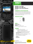
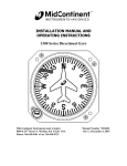
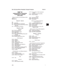
INSTALLATION MANUAL AND
OPERATING INSTRUCTIONS
4300-XXX Series Electric Attitude Indicator
With Battery Backup
MID-CONTINENT INST. CO., INC
MANUAL NUMBER 9015762
Mid-Continent Instruments, Wichita, KS
Table of Contents
Section 1
1.1
1.2
1.3
1.4
1.5
1.6
General Description
Purpose of Equipment
Physical Description
Functional Description
Gyro Warning Flag
Options and Configurations
Specifications
Page
5
5
5
5
6
6
6
Section 2
2.1
2.2
2.3
2.3.1
2.3.2
2.3.3
2.4
2.5
2.6
Installation
General
Pre-Installation Inspection
Parts
Included Parts
Installer Supplied Parts
Additional Optional Parts
Equipment Location
Installation
Continued Airworthiness
11
11
11
12
12
12
12
12
13
14
Section 3
3.1
3.2
3.3
3.4
3.5
3.6
Operation
General
Starting Procedures
In-Flight Procedures
Dynamic Errors
Standby Battery Operation
Equipment Limitations
19
19
19
19
19
20
22
Figure No.
1.1
1.2
2.1
2.2
2.3
2.4
2.5
2.6
2.7
List of Illustrations
Display Configurations
Typical Indicator Display Detail
Outline Drawings
Rear-Mount Cutout Dimensions
Front-Mount Cutout Dimensions
Remote Mount Standby Battery Option
with 9015671 Kit
Nominal Battery Discharge Rate at 20°C
Effect of Low Temperature on Battery Capacity
Life Characteristics in Standby Use
Table No.
1.1
1.2
1.3
1.4
List of Tables
Options Table
Physical Characteristics
Performance
Light Tray Assembly Options
Rev J, September 1, 2009
Manual Number 9015762
8
10
16
17
17
18
20
21
21
6
6
7
7
Page 3 of 22
Mid-Continent Instruments, Wichita, KS
Revision Detail
Rev.
N/R
A
Date
10/1/03
11/4/03
B
05/25/04
C
09/15/04
4307
D
03/28/05
4503
4834
4956
E
F
G
01/04/06
04/30/07
12/13/07
5214
H
05/26/09
5270
J
09/01/09
ECO
Rev J, September 1, 2009
Detail
Complete issue
Revise text for improved short battery test. Add text to Sec. 2.6.2.B
for P/N 36029 battery charger.
Update display configurations Fig. 1.1, update connector pinout:
Lighting (No polarity), revise currents in table 1.3, add bezel dims
to panel cutouts, add DO-160D environmental test qualification in
Table 1.2.
Revise section 2.6. Update DO-160D statement in section 1.6 from
A2… to C1… for 35K altitude.
Add Special HIRF Considerations paragraph to section 2.5. Update
DO-160D statement in section 1.6 from …[RR]… to …[WW]…
Add section 2.6.1D.2 regarding automatic capacity test.
Delete -40X single voltage versions.
Update DO-160 qualification in section 1.6 from …[WW] to …[WF]…
and from …[A3C3]… to [A3H33]. Remove paragraph pertaining to
Special HIRF Considerations in section 2.5.
Note: This change is incorporated only on units identified as Mod
Status 4 as indicated on the unit nameplate.
Change 4300-4XX to 4300-XXX with Battery Backup to include OEM
specific versions.
Remove first paragraph in section 3.6 stating that Indicator is not
to be used as a reference for aerobatic flight. Update DO-160
qualification in section 1.6 from …[(SBM)(RBB1)]… to
…[(SBM)(RBB1)(P)]…
Manual Number 9015762
Page 4 of 22
Mid-Continent Instruments, Wichita, KS
Section 1: General Description
1.1
Purpose of Equipment
The Model 4300-XXX Electric Attitude Indicator with Battery Backup incorporates a moving
display that simulates the earth’s horizon and provides the pilot with a real time visual indication
of the aircraft pitch and roll attitude relative to the indicator symbolic airplane.
The instrument can function as a primary or standby indicator with special configurations
available to match existing systems or electronic flight displays. In the event aircraft electrical
power is lost, the indicator will switch to an internal backup power source (rechargeable sealed
lead acid battery) to permit continued operation of the indicator. Panel tilt, lighting color/voltage,
non-trimmable knob cover, front mount adapter plates and a slip indicator are available as
options.
1.2
Physical Description
The 4300-XXX Electric Attitude Indicator with Battery Backup incorporates pitch and roll displays
that are mechanically linked to a spinning mass gyroscope. The horizon bar moves behind the
symbolic airplane. Precession error is corrected by the 4300’s erection system or by pulling the
“PULL TO CAGE” knob. If the gyro motor is not receiving sufficient power to operate, a warning
flag drops into view. This will normally occur only if the unit is turned off or after the internal
standby battery is exhausted.
1.3
Functional Description
Model 4300-XXX Electric Attitude Indicators employ an efficient electrically driven internal vertical
gyroscope assembly incorporating a special air erection mechanism. This mechanism
simultaneously erects the pitch and roll axes of the gyroscope. Movement of the aircraft
generates a reaction of the display that simulates the visual reference seen by the pilot when
looking outside at the earth’s true horizon line.
The 4300-XXX Electric Attitude Indicator with Battery Backup offers the unique feature of a selfcontained standby power source. Advances in the design of this gyro system allow it to operate
for about one hour after main input power is lost, depending on the battery condition at the time
of power failure.
Anytime aircraft power is absent, with the unit in either power loss warning mode or turned off,
pushing the STBY PWR button will put the unit into the standby power mode. The instrument will
run from standby power until the internal battery is exhausted. If the unit is already running on
standby power (internal battery), pushing the STBY PWR button will turn the unit off completely.
Pushing the STBY PWR button again will restore unit operation to standby power. Restoring
aircraft power will clear any standby power mode and automatically resume standby battery
charging.
The indicator will operate on an input voltage of 10 to 32 volts. An integral lighting system
featuring a user replaceable light tray assembly operates from the aircraft lighting bus and is
available in 5V, 14V, or 28V versions (dependent on configuration). In standby power operation,
low intensity LED dial lighting is automatically turned on to provide nighttime visibility.
The internal battery is designed for emergency use only. Frequent use, extended discharging,
extended lack of charging, misuse and age will require battery replacement. Replacement can be
done in the field with or without removal of the attitude indicator. Do not operate this model
Rev J, September 1, 2009
Manual Number 9015762
Page 5 of 22
Mid-Continent Instruments, Wichita, KS
without the specified battery intact. Battery substitution, modification, misuse and lack of
specified maintenance will void all warranties and hold the manufacturer harmless from any and
all claims or legal actions.
Refer to an FAA authorized maintenance facility for testing and maintenance of this instrument
excluding battery or light tray replacement.
1.4
Gyro Warning Flag
A warning circuit monitors the electrical voltage used to power the gyro motor. When the
Indicator is turned off, or after the internal battery is discharged, the gyro warning flag comes
into view. Anytime aircraft power is lost, including normal end-of-flight power down, the unit will
switch to the Power Loss Warning mode. If the STBY PWR button on the face of the instrument
is not pushed before the end of the (nominal) one-minute timing period, the instrument will turn
itself off and the gyro warning flag will appear. If the STBY PWR button is pushed, the gyro will
run from standby power until the internal battery is exhausted before the gyro warning flag
appears.
1.5
Options and Configurations
Options Table
Panel Tilt Calibration
Lighting Voltage
Lighting Color
Miscellaneous Parts:
1.6.
0° to 20°
5V, 14V, or 28V (See Table 1.4)
Blue/White, White, or Red (See Table 1.4)
Non-Trimmable Symbolic Airplane Knob Cover (P/N 36022)
Slip Indicator Kit (P/N 36023)
Front Mount Kit: 3/32” thk (P/N 36028-1) or 1/2” thk (P/N 36027-1)
Panel Wedges: 3° (P/N PW3R-3) or 4° (P/N PW3R-4)
Mating Connector Kit (P/N 9015514)
Remote Battery Mounting Kit (P/N 9015671)
Replacement Standby Battery (P/N 9015607)
Battery Charger (P/N 36029)
Table 1.1
Specifications
Physical Characteristics:
Qualification:
Environmental Qualification:
Weight:
Dimensions:
Mating Connector:
Cover Glass
Instrument Panel Mounting:
Rev J, September 1, 2009
FAA-TSO-C4c
RTCA DO-160D Environmental Category
C1BAB[(SBM)(RBB1)(P)]XXXXXXZZAZZ[WF]M[A3H33]XXA
3.7 pounds (2.7 pounds without battery)
Length behind panel (not including mating connector)
6.6 inches long max. (battery not installed)
8.6 inches long max. (battery installed)
3.28 inches high maximum.
3.28 inches wide maximum.
MS3116F8-4S or equivalent (MCI P/N 9015514)
HEA (anti-reflective) coated.
Rear mount. Front mount with adapter plate.
Table 1.2
Manual Number 9015762
Page 6 of 22
Mid-Continent Instruments, Wichita, KS
Performance:
Reliability
Initial Erection:
Final Erection:
Erection Rate:
Warning Flag:
Symbolic Airplane:
Power Consumption:
Starting:
Running:
Lighting:
7500 Hour Mean Time Between Failure (MTBF).
The "PULL TO CAGE" knob will erect the gyroscope to within 2.0°
of case vertical in roll and pitch from any position at any time.
The vertical gyroscope should be allowed to spin up for 3 minutes
after rated power is applied and after initial erection. After 5
minutes the final erection accuracy of pitch and roll will be within
1° of vertical.
Gyroscope erects to local vertical in pitch and roll at 2.5° per
minute minimum.
A gyro warning circuit provides for continuous monitoring of gyro
voltage. If loss of gyro motor voltage occurs, the red warning flag
will appear. See section 3.5 for battery operation.
The adjustment range is ± 4° minimum from the zero pitch
position.
1.8A maximum (at 14 VDC input)
0.9A maximum (at 28 VDC input)
Nominal 0.55A ±15% (at 14 VDC input)
Nominal 0.27A ±15% (at 28 VDC input)
2.5 watts maximum (for all models using 5V, 14V, or 28V lighting)
Table 1.3
Light Tray Assembly Options
P/N 9015640-( )
5V 14V 28V
Blue/White
-1
-2
-3
White
-4
-5
-6
Red
-7
-8
-9
Table 1.4
Rev J, September 1, 2009
Manual Number 9015762
Page 7 of 22
Mid-Continent Instruments, Wichita, KS
Face Layout A
Face Layout B
Rotating Roll Dial
Fixed Pointer
Traditional Symbolic Airplane
Standard Horizon Dial
Fixed Roll Dial
Rotating Pointer
Traditional Symbolic Airplane
Standard Horizon Dial
Face Layout C
Face Layout D
Rotating Roll Dial
Fixed Pointer
Delta Symbolic Airplane
Standard Horizon Dial
Fixed Roll Dial
Rotating Pointer
Delta Symbolic Airplane
Standard Horizon Dial
Face Layout E
Face Layout F
Rotating Roll Dial
Fixed Pointer
High Resolution Horizon Dial
Traditional Symbolic Airplane
Fixed Roll Dial
Rotating Pointer
High Resolution Horizon Dial
Traditional Symbolic Airplane
Figure 1.1
Display Configurations
Rev J, September 1, 2009
Manual Number 9015762
Page 8 of 22
Mid-Continent Instruments, Wichita, KS
Face Layout G
Face Layout H
Rotating Roll Dial
Fixed Pointer
Delta Symbolic Airplane
High Resolution Horizon Dial
Fixed Roll Dial
Rotating Pointer
Delta Symbolic Airplane
High Resolution Horizon Dial
Model
Number
4300-411
4300-412
4300-413
4300-414
Input
Voltage
10 to 32 VDC
10 to 32 VDC
10 to 32 VDC
10 to 32 VDC
Roll Dial
Horizon Dial
Rotating
Fixed
Rotating
Fixed
Standard
Standard
Standard
Standard
4300-431
4300-432
4300-433
4300-434
4300-2XX
10 to 32 VDC
10 to 32 VDC
10 to 32 VDC
10 to 32 VDC
OEM Specific
Rotating
Fixed
Rotating
Fixed
High
High
High
High
Resolution
Resolution
Resolution
Resolution
Symbolic
Airplane
Traditional
Traditional
Delta
Delta
Face
Layout
A
B
C
D
Traditional
Traditional
Delta
Delta
E
F
G
H
Figure 1.1, Cont.
Display Configurations
Rev J, September 1, 2009
Manual Number 9015762
Page 9 of 22
Mid-Continent Instruments, Wichita, KS
Roll Pointer:
A) Fixed roll pointer: Indicates aircraft roll displacement relative to a
rotating roll dial.
B) Rotating roll pointer: Indicates aircraft roll displacement relative to
a fixed roll dial.
Gyro Warning Flag:
If loss of operating voltage should occur, gyro warning flag will come
into view.
Display:
Lower area of display, when referenced to the symbolic airplane,
indicates aircraft nose is below horizon or in a dive attitude. Upper area
of display indicates aircraft nose is above horizon or in a climb attitude.
Symbolic Airplane:
Indicates roll and pitch attitude relative to the horizon. The symbolic
airplane can be moved (pitch only) using the symbolic airplane
adjustment knob.
Horizon Line:
Indicates earth horizon relative to aircraft pitch and roll attitude.
Caging knob:
(Manual Erection)
When pulled, manually erects the gyro vertical to the case orientation.
Symbolic Airplane
Adjustment Knob:
Used to adjust the symbolic airplane.
Typical Electric Attitude Indicator Display
(Rotating Roll Dial, Fixed Roll Pointer, Traditional Wing Symbolic Airplane Shown)
Figure 1.2
Rev J, September 1, 2009
Manual Number 9015762
Page 10 of 22
Mid-Continent Instruments, Wichita, KS
Section 2: Installation
2.1
General
This section contains mounting, electrical connections and other information required for
installation. After installation of cabling and before installation of the equipment, ensure that
power is applied only to the pins specified in the interconnection diagram.
CAUTION: GYROS ARE DELICATE INSTRUMENTS!
THE FOLLOWING PRECAUTIONS MUST BE OBSERVED!!
A. A high gyroscope failure rate can be directly related to rough or improper handling.
Gyros are delicate and cannot withstand the shock of being dropped, jarred, or
struck by pieces of equipment. Do not place gyros on any hard surface. Pad with
generous foam. Handle like eggs!
B. To prevent damage to a gyro, the instrument should be transported to and from the
aircraft in it’s original shipping container. If this is impractical, the gyro should be
hand-carried carefully in an upright position.
C. A gyro should never be removed while it is spinning or running down. The instrument
normally operates at high RPM and may take 10 minutes or longer to run down. If it
is removed while running and tilted more than 20 degrees, the gyro can develop a
gimbal lock. The gimbal will tumble and start to spin. If gimbal lock occurs while the
rotor is turning, the gimbal may spin fast enough to damage the gimbal bearings,
requiring an overhaul.
D. A malfunctioning gyro should be handled with the same care given a new
instrument. Most malfunctioning instruments can be repaired and returned to
service. Using proper handling procedures during removal prevents additional
damage and helps ensure possible reuse.
2.2
Pre-installation Inspection
A. Unpacking: Carefully remove the attitude indicator from shipping container. The
shipping container and packing materials should be retained for use should the
attitude indicator require future shipment.
B. Inspect for Damage: Inspect the shipping container and indicator for any signs of
damage sustained in transit. If necessary, return attitude indicator to the factory
using the original shipping container and packing materials. File any claim for
damages with the carrier.
C. CAUTION: The unit is shipped with the battery cable disconnected to
prevent inadvertent operation of the indicator during shipping. If the cable
was found connected when received, check the battery condition per section 2.6.3
and then reconnect the battery during instrument installation if it checks out ok.
Remaining discharged for extended periods may permanently damage the battery
pack.
Rev J, September 1, 2009
Manual Number 9015762
Page 11 of 22
Mid-Continent Instruments, Wichita, KS
2.3
Parts
2.3.1 Included Parts
A. Model 4300-( ) Electric Attitude Indicator including Battery Pack (P/N 9015607).
B. Mating Connector, MS3116F8-4S or equivalent (P/N 9015514).
C. Installation Manual (P/N 9015762)
2.3.2 Installer Supplied Parts
Mounting Screw, 6-32UNC-2A. Three (3) required. (1” long screws are suggested for
panel thickness between 0.05 and 0.19, but may not be optimum in some installations.
The installer will need to determine what is correct for a particular installation.)
****CAUTION****
Do not exceed 1.06” screw depth into bezel!
2.3.3 Additional Parts that may be required
A.
B.
C.
D.
E.
2.4
Symbolic Airplane Adjustment Knob Cover Kit: (P/N 36022)
Slip Indicator Kit (P/N 36023)
Front Mount Kit: 3/32” thk (P/N 36028-1) or 1/2” thk (P/N 36027-1)
Panel Wedges: 3” (P/N PW3R-3) or 4” (P/N PW3R-4)
Remote Battery Mounting Kit (P/N 9015671)
Equipment Location
The attitude indicator should be located within the aircraft in accordance with the following
considerations:
A. The indicator is ideally located in the instrument panel directly in line with the pilot's
normal line of sight. The "PULL TO CAGE" knob should be within easy reach.
Installations that result in viewing angles in excess of 30 degrees may reduce display
readability.
B. Compare the space requirements of the indicator with the installation area being
considered.
C. The power cable should not run adjacent to heaters, engine exhausts, or other heat
sources. Also, take care to route and tie the cable away from aircraft controls and
cables.
D. If remote mounting the standby battery, the cable length from the battery to the unit
should be kept as short as practical using wire of 22 AWG minimum. 18 AWG wire is
recommended for cable runs over 50 feet. Remote mounting the battery in a location
subject to extreme temperature variations may dramatically shorten the emergency
operation time available for the attitude indicator as well as the expected battery
lifetime (Fig 2.7 and 2.8). For optimum battery performance it is recommended to
mount the battery in a temperature controlled section of the aircraft.
Rev J, September 1, 2009
Manual Number 9015762
Page 12 of 22
Mid-Continent Instruments, Wichita, KS
2.5
Installation
NOTE: Before installing unit, verify the option label on the unit matches the
aircraft requirements for instrument voltage, lighting voltage/color,
and panel tilt.
Install the Electric Attitude Indicator within the aircraft in accordance with the aircraft
manufacturer’s instructions and the following steps:
A. Refer to Figure 2.1 for installation dimensions and electrical information.
B. Ensure the available instrument panel cutout meets the requirements of the indicator.
See Fig. 2.2 for details.
C. If a remote mounted standby battery is preferred:
1. Remove 4 screws mounting the standby battery to the rear of the indicator and
remove the standby battery.
2. Re-install the 4 screws into the rear of the indicator.
3. Mount the standby battery in a protected location inside the aircraft using
9015671 kit, oriented at any angle from horizontal to vertical. If mounted
vertically, cable side must be down as shown in Fig. 2.4.
4. Make an extension cable, 22 AWG minimum, using the connectors provided in
9015671 kit.
D. Plug the standby battery cable into the rear of the Indicator.
NOTE: The cable is disconnected for shipping to prevent accidental
activation and battery discharge in transit.
E. The unit may start when the battery is connected. Momentarily push the STBY PWR
button, twice if necessary, until the Red Gyro Warning flag shows. Continue the
installation after the Gyro has spun down.
F. Attach aircraft electrical system cable to the round 4-pin indicator connector and insert
the indicator into the instrument panel cutout.
G. Secure the indicator to the instrument panel using the screw sizes called out in the
mounting instructions. Length of screws will be determined by aircraft instrument panel
thickness. The aircraft manufacturer or the installation facility is responsible for supplying
appropriate installation hardware.
H. Apply the correct input power to the indicator.
I.
The Gyro Warning flag (red) will be out-of-view.
J.
Check to determine that indicator internal lighting is working correctly.
K. After the unit has been powered for at least a 3-minute spin-up period, press and hold
the STBY PWR button. A green light will illuminate under the word TEST, indicating the
standby battery is functioning properly. If a red light illuminates, the standby battery will
need to be charged for 1 hour before retesting. If the standby battery fails to pass the
short battery capacity test after 1 hour charging, a full battery capacity test must be
performed. See Sect. 2.6.1D.
Rev J, September 1, 2009
Manual Number 9015762
Page 13 of 22
Mid-Continent Instruments, Wichita, KS
2.6
2.6.1
Continued Airworthiness
BATTERY
A. The battery is designed to be a user replaceable item if desired. Recommended
replacement interval for the standby battery (P/N 9015607) is 3 years because of
diminished capacity (See Figures. 2.6 and 2.7 for more information).
NOTE: The standby battery contains lead. Do not dispose of in local
landfills or other environmentally sensitive areas.
NOTE: Recycle the battery in accordance with state and local
regulations. For recycle locations visit www.rbrc.com or call 1800-8-BATTERY (1-800-822-8837)
B.
In normal use, the 4300-XXX with Battery Backup supplies the proper float charge
voltage to maintain its battery at peak capacity, however, the battery will slowly selfdischarge if the attitude indicator is left unused for long periods (over 3 months). In
addition, self-discharge rates are directly related to the storage temperature. The higher
the storage temperature the faster the self-discharge rate. Therefore, the battery should
be periodically charged or removed from the installation and maintained on a charger.
C.
If the 4300-XXX Electric Attitude Indicator with Battery Backup has not been operated
for an extended period (more than 3 months) to keep the battery charged, the standby
battery should be charged by one of the following methods.
1. Keep the battery plugged into the 4300 Electric Attitude Indicator. Run the unit
overnight (approx. 15 hours) at the rated voltage.
2. Float Charging: Disconnect the battery from the indicator. Connect the battery to a
constant voltage source (battery plug (pin 1) red wire = positive) of 20.4 to 20.6
VDC continuously. Float charging may take 24 hours or longer to charge a
battery pack.
3. Routine Charging: Disconnect the battery from the indicator. Connect the battery to
a constant voltage source (battery plug pin 1 red wire = positive) of 21.6 to 22.1
VDC with a current limit of 0.1 ampere maximum. When the charging current
drops to approximately 5mA, the battery is fully charged and should be
disconnected. Leaving 21.6 to 22.1 VDC charge voltage on the battery for an
extended time will degrade its life. If continuous maintenance of the charge is
desired, refer to step 2, Float Charging.
****WARNING****
Battery out gassing and a rotten egg odor may occur due to
prolonged high rate overcharging and may result in battery
damage. MCI recommends that the battery assembly be replaced if
out gassing has occurred.
4. MCI Battery Charger/Tester P/N 36029 may be used. This Battery Charger/Tester will
apply an initial charge, per step 3 above, and then automatically switch to maintain a
float charge, per step 2 above, indefinitely after initial charging is complete.
Rev J, September 1, 2009
Manual Number 9015762
Page 14 of 22
Mid-Continent Instruments, Wichita, KS
D. On at least an annual basis, as well as any time there may be a question about battery
performance (life) a Full Capacity Test should be performed. To perform a Full Battery
Capacity Test use one of the following methods.
1. Manual.
a. Disconnect battery pack from the 4300 Attitude Indicator.
b. Ensure the battery is completely charged and at or near normal room
temperatures (20-25°C). (Ref. Sect. 2.6.1C)
c. Connect the battery to a load of 90 ohms (rated for 10 watts) for 60 minutes
while monitoring the battery voltage level.
a) If the battery voltage is above 15.0 volts at the end of the 60-minute battery
capacity test, the battery should be capable of continued use after
recharging is complete.
b) If the battery voltage drops below 15.0 volts before the end of the 60minute test period while under load, the battery pack is nearing the end of
its service life and should be replaced.
d. Recharge the battery pack immediately.
2. Automatic.
a. Use MCI Battery Charger/Tester P/N 36029. When in the capacity test
mode, this Charger/Tester will charge the battery and measure the time
required for discharge. (60 minutes minimum) The unit will then
automatically switch to the charge/float mode to maintain the standby
battery at full charge.
****WARNING****
The battery may be permanently damaged if it is left in a
discharged state. Recharge a discharged battery as soon as
possible and maintain with a float charge for maximum battery
life.
2.6.2
ATTITUDE INDICATOR
No periodic scheduled maintenance or calibration is necessary for continued airworthiness of
the 4300 series Electric Attitude Indicator. If the unit fails to perform to specifications, it must
be removed and serviced by a qualified service facility.
Rev J, September 1, 2009
Manual Number 9015762
Page 15 of 22
Mid-Continent Instruments, Wichita, KS
Figure 2.1 Outline Drawing
Rev J, September 1, 2009
Manual Number 9015762
Page 16 of 22
Mid-Continent Instruments, Wichita, KS
Figure 2.2: Panel Cutout Dimensions
Figure 2.3: Front Mount Panel Cutout Dimensions
Rev J, September 1, 2009
Manual Number 9015762
Page 17 of 22
Mid-Continent Instruments, Wichita, KS
UP
End View
(When mounted
vertically)
Side View
Figure 2.4: Remote Mount Standby Battery Option,
using 9015671 Kit
Contents of Standby Battery Remote Mount Kit:
Part Number
7016975
7016983
7017676
7018328
7018336
9015725
Rev J, September 1, 2009
Description
Crimp Pin
Connector Housing Cap
Screw, 4-40x3/16 Pan Head Phillips
Contact Socket
Connector Housing Plug
Battery Mount Plate
Manual Number 9015762
Qty
(2)
(1)
(4)
(2)
(1)
(1)
Page 18 of 22
Mid-Continent Instruments, Wichita, KS
Section 3: Operation
3.1
General
This section describes the Model 4300-XXX Electric Attitude Indicator operating procedures. The
indicator is required to be installed in an aircraft with the specified inputs applied. Figure 1.2
provides an illustration of a typical Model 4300 display and a table describing indicator functions.
3.2
Starting Procedures
The following operational procedures are recommended when preparing the indicator for use:
****CAUTION****
THE INDICATOR MAY BE DAMAGED IF THE “PULL TO CAGE”
KNOB IS RELEASED WITH A “SNAP.” SLOWLY RELEASE “PULL
TO CAGE” KNOB AVOIDING A “SNAP” RELEASE.
NOTE: Indicator may be momentarily caged by pulling “PULL TO CAGE”
knob to the fully extended position, holding knob until the
display stabilizes, and then allowing the knob to return to the
normal position.
A. Apply power to the indicator. Note that the Gyro Warning flag (red) will pull out-ofview. Allow three minutes for presentation stabilization.
B. On models with trim adjustment, rotate the symbolic airplane adjustment knob for
the desired pitch attitude presentation, i.e. aligning the symbolic airplane with the
horizon.
C. If caging is required, caging should be accomplished when the aircraft is in a wings
level, normal cruise attitude, as indicated by other instruments or the earth’s horizon.
If the gyro is caged when the aircraft is not in this attitude, the resulting attitude
presentation immediately after caging will be in error by the difference between true
vertical and actual aircraft attitude. Small errors in caging erection will be corrected
by the indicator to true vertical in pitch and roll at 2.5° per minute minimum (5°/min.
nominal).
3.3
In-Flight Procedures
A. Adjust the symbolic airplane to obtain desired pitch attitude presentation after takeoff.
B. In the event of errors in excess of 10° caused by extended bank or fore-aft
acceleration, the indicator should be momentarily caged after the aircraft is returned
to level flight.
3.4
Dynamic Errors
A. Turn Induced Errors
Pitch indication errors resulting from a standard coordinated turn (180 degrees in
one minute at a true airspeed of 156 knots) will not exceed 3°. Dynamic errors
developed under non-standard conditions may be greater. Errors that develop will be
self corrected by the internal erection system or manually corrected by the actuation
of the caging system.
Rev J, September 1, 2009
Manual Number 9015762
Page 19 of 22
Mid-Continent Instruments, Wichita, KS
B. Acceleration & Deceleration Errors
Pitch/roll indicating errors may occur due to accelerations experienced during takeoff,
climb-out, descent, and landing. Errors that develop will be self-corrected by the
internal erection system or manually corrected (in straight and level flight) by the
actuation of the caging system.
C. Taxiing Errors
A pitch and roll indicator display error of approximately 1° will occur during a sudden
90° ground turn. A pitch indicator display error of approximately 2° will occur during
a sudden 180° ground turn. Errors that develop will be self corrected by the internal
erection system or manually corrected by the actuation of the caging system.
3.5
Standby Battery Operation
Supply aircraft power to the instrument. The internal standby battery charges automatically while
the gyro is running. Lighting is on a separate circuit connected to the aircraft lighting bus.
A. Normal Flight
At loss of external power, an amber LED will flash indicating a Power Loss Warning.
With no further action from the pilot, the unit will turn off automatically (gyro flag in
view) after approximately one minute. This is to prevent battery discharge at the end
of a flight when the master power switch is placed in the off position.
B. Loss of Aircraft Power
When the instrument switches to Power Loss Warning, the amber LED flashes for
approximately one minute. This is intended to attract the pilot’s attention and
indicate that there has been a loss of primary power to the 4300 Attitude Indicator.
Pushing the STBY PWR button on the face of the instrument will allow the unit to
continue operating on the standby battery for nominally one (1) hour or until the
battery is exhausted. See Fig 2.5 for more information on battery discharge rate. The
gyro warning flag remains out of view, which indicates the gyroscope is valid and
running on standby battery power. An independent standby dial lighting system also
operates in this mode.
Any time aircraft power is absent, with the unit in either Power Loss Warning or shut
off, pushing the STBY PWR button will put the unit in the standby power mode. The
instrument will run from standby power until the standby battery is exhausted. If the
unit is running on the standby battery, pushing the STBY PWR button will turn the
unit off. Pushing the STBY PWR button again will restore standby power and standby
lighting.
Restoring aircraft power will clear any standby operation and resume automatic
battery charging.
Rev J, September 1, 2009
Manual Number 9015762
Page 20 of 22
Mid-Continent Instruments, Wichita, KS
C. Standby Battery Test
The control panel on the front of the instrument incorporates a manual test feature.
This test feature places the standby battery pack under load for approximately one
minute (the gyro is used as a load) while displaying either a red or green light under
the word TEST on the front panel.
To initiate this test:
1. Turn on the indicator with aircraft power and allow the unit to spin up for 3
minutes or more
2. Press and hold the STBY PWR button. After several seconds the amber LED
will start flashing, indicating unit has latched into Battery Test Mode. The
test runs for approximately one minute, during which time the amber LED
flashes continuously and either a red or green light is displayed under the
word TEST.
3. Visually monitor the test lights until the amber LED stops flashing, signaling
the end of the test.
4. A green light throughout the test indicates the standby battery pack is
healthy and should be able to function normally. A red light at any time
during the test means that the standby battery is at least in need of
charging, and possibly of replacement.
Note:
A green light throughout this short test does not guarantee that
a full hour of operation time is available. Actual operation time
on the battery may vary considerably depending on
temperature, charge status, and battery condition. (See Sect.
3.6 for more details).
Complete charging may be required to bring the battery up to full charge if it has
been stored for more than four months or if it has been partially discharged. If a
steady red light is observed at any time during the test, charge the standby battery
completely, using one of the methods described in section 2.6 and retest the battery.
If after charging, the test still fails, service may be required.
It is not recommended to test the battery when aircraft power is not available, but it
is possible to put the indicator into test mode while operating on the backup battery.
The test will run, but the indicator will turn off at the end of the test period. To turn
the indicator back on, simply push the STBY PWR button again.
Fig. 2.5: Nominal Battery Discharge Rate at 20°C
Rev J, September 1, 2009
Manual Number 9015762
Page 21 of 22
Mid-Continent Instruments, Wichita, KS
3.6
Equipment Limitations
The Mid-Continent 9015607 battery pack is part of a complete system. When remote mounted,
the 9015607 battery pack MUST be installed with the Mid-Continent 4300-XXX series Electric
Attitude Indicator with Battery Backup in order to be approved as a complete TSO’d system.
This battery is not FAA approved if installed or used in any other way.
Actual operation time on the battery may vary considerably depending on temperature, charge
status, and battery condition. Low temperatures will temporarily degrade battery capacity as
shown in Fig. 2.6. Internal chemistry will slowly degrade battery capacity over several years of
operation as shown in Fig 2.7, even when correctly maintained. A poorly maintained battery will
suffer accelerated degradation in excess of the guidelines given in this document. Extended
storage in a discharged state or at high ambient temperatures, and over-charging will all
permanently damage a battery. Complete charging is required to bring the battery up to full
capacity if it has been stored for more than four months or if it has been partially discharged.
Capacity (%)
100
80
60
40
20
0
-20
-10
0
10
20
30
40
50
Temperature (°C)
Fig. 2.6: Effect of Low Temperature
On Standby Battery Capacity
Rev J, September 1, 2009
Fig. 2.7: Life Characteristics
In Standby Use
Manual Number 9015762
Page 22 of 22