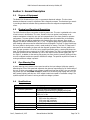
1
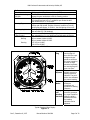
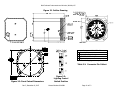
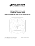
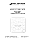
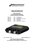
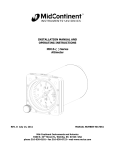
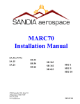
INSTALLATION MANUAL AND OPERATING INSTRUCTIONS 3300 Series Directional Gyro Mid-Continent Instruments and Avionics 9400 E 34th Street N, Wichita, KS 67226 USA Phone 316-630-0101 Fax 316-630-0723 Manual Number 9016481 Rev C, December 6, 2007 Mid-Continent Instruments and Avionics, Wichita, KS FOREWORD This manual provides information intended for use by persons who, in accordance with current regulatory requirements, are qualified to install this equipment. If further information is required, please contact: Mid-Continent Instruments and Avionics Attn: Customer Service Dept. 9400 E. 34th ST North Wichita, KS 67226 USA Phone 316-630-0101 Fax 316-630-0723 We welcome your comments concerning this manual. Although every effort has been made to keep it free of errors, some may occur. When reporting a specific problem, please describe it briefly and include the manual part number, the paragraph/figure/table number, and the page number. Send your comments to: Mid-Continent Instruments and Avionics Attn: Technical Publications 9400 E. 34th ST North Wichita, KS 67226 USA Phone 316-630-0101, Fax 316-630-0723 [email protected] www.mcico.com Copyright 2007 Mid-Continent Instruments and Avionics Rev C, December 6, 2007 Manual Number 9016481 Page 2 of 12 Mid-Continent Instruments and Avionics, Wichita, KS Table of Contents Page 5 5 5 5 5 Section 1 1.1 1.2 1.3 1.4 General Description Purpose of Equipment Physical and Functional Description Gyro Warning Flag Specifications Section 2 2.1 2.2 2.3 2.3.1 2.3.2 2.4 2.5 2.6 Installation General Pre-Installation Inspection Parts Included Parts Installer Supplied Parts Equipment Location Installation Continued Airworthiness 7 7 7 8 8 8 8 8 9 Section 3 3.1 3.2 3.3 3.4 Operation General Starting Procedures In-Flight Procedures Equipment Limitations 11 11 11 11 11 1.1 2.1 2.2 2.3 Figures Typical Directional Gyro Display Detail Outline Drawing Panel Cutout Dimensions Voltage Control Switch Position 6 10 10 10 1.1 1.2 2.1 Tables Physical Characteristics Performance Connector Pin Callout 5 6 10 A Appendices DO-160E Environmental Qualification Form 12 Rev C, December 6, 2007 Manual Number 9016481 Page 3 of 12 Mid-Continent Instruments and Avionics, Wichita, KS Revision Detail ECO 4811 4943 Rev. A B C Date 1/25/07 2/27/07 11/29/07 Rev C, December 6, 2007 Detail Initial Release. Correct Typo on Append A & Sec 1.4: Temp. Variation “S2” was “C2”. Add comments for unit lighting in sections: 1.2, 1.3, 1.4, 2.5.B, 2.5.D, 2.5.G, 3.2.A. Change figure 2.1 and table 2.1. Add figure 2.3. Manual Number 9016481 Page 4 of 12 Mid-Continent Instruments and Avionics, Wichita, KS Section 1: General Description 1.1 Purpose of Equipment The Model 3300 Directional Gyro (DG) is a gyroscopic directional indicator. This short-term directional reference is used in conjunction with a magnetic compass. The directional gyro excels in providing a direction indication during maneuvers when the magnetic compass develops errors. 1.2 Physical and Functional Description The 3300 Directional Gyro incorporates a spinning mass rotor. This rotor is gimbaled so the rotor is free to move in all directions. The rotor, housed in the inner gimbal, incorporates an air erection mechanism to keep the rotor spin axis perpendicular to the outer gimbal for optimum performance. The outer gimbal is linked with a precision gear drive mechanism to the display dial. The dial has five-degree graduations with numerals every thirty degrees. Every ninety degrees is a cardinal reference letter (N, E, S, W). The display glass has a symbolic airplane for quick heading reference as well as index marks every 45 degrees. The Push To Cage knob brings the inner gimbal to level position, which is used primarily for startup. This Push To Cage knob is also used to set the heading to agree with the magnetic compass. When the rotor speed is too low for proper operation or if the unit is not receiving sufficient power, a warning flag drops into view. The directional gyro requires 10 to 32 VDC input voltage. The 3300-11 incorporates internal LEDs that operate on a user selectable 5V, 14V or 28V input from the aircraft lighting bus. For the 3300-11, in addition to the warning flag coming into view, the dial (numeral) lighting will also turn off to indicate invalid rotor speed or insufficient voltage. The symbolic airplane will remain lit as long as sufficient voltage is present. 1.3 Gyro Warning Flag A power warning circuit monitors rotor speed as well as the input voltage. Valid rotor speed is determined as 70% of full speed and represents the minimum requirement for full functionality of the unit. If either rotor speed or input voltage is insufficient (less than 10VDC), the gyro warning flag comes into view. For 3300–11 only: In addition to the warning flag coming into view, the dial (numeral) lighting will also turn off to indicate invalid rotor speed or insufficient voltage. The symbolic airplane will remain lit as long as sufficient voltage is present. 1.4 Specifications Physical Characteristics: Qualification: Environmental Qualification: Weight: Dimensions: Mating Connector: Cover Glass Instrument Mounting: Rev C, December 6, 2007 FAA TSO-C5e RTCA DO-160E Environmental Category D1S2AER(B1)XXXXXXZZAZ[ZC][WW]M[A3C3X]XXAX 3300-10: 1.9 lbs 3300-11: 2.0 lbs Length behind panel (not including connector) 4.65 inches long maximum. 3.28 inches high maximum. 3.28 inches wide maximum. MS3116F8-4S or equivalent (MCI P/N 9015514) HEA (anti-reflective) coated Rear panel mount Table 1.1 Manual Number 9016481 Page 5 of 12 Mid-Continent Instruments and Avionics, Wichita, KS Performance: Reliability Caging and Heading Set Knob Drift Rate Warning Flag Operating Angle Limit Lighting (3300-11 only) Power Rating: Starting Running 2500 Hour Mean Time Between Failure (MTBF) The "PUSH" knob will erect the gyroscope to case horizontal and engage the gear mechanism to set the heading position. When the gyro is mounted to a rotating scorsby test stand tilted to 3-degrees and set at 5 to 7 oscillations per minute the drift shall be less than 4° in 10 minutes. A gyro warning circuit provides for continuous monitoring of input voltage and rotor speed. If either of these is insufficient, the red warning flag will appear. In 3300-11, the dial lighting will turn off. Heading: No Limit (360°) Pitch and Roll: 55° (all headings) Internal white LED with backlit dial. Lighting control voltage is user selectable for 5, 14 or 28VDC and has adjustable brightness. Will not exceed 1.4A at 14 VDC. Will not exceed 0.6A at 28 VDC. 0.37-0.51 at 14 VDC. 0.18-0.25 at 28 VDC. Table 1.2 Warning Flag Symbolic Airplane Index Marks Caging and Heading Set Knob On startup the warning flag will show until the input voltage and rotor speed are sufficient for proper operation. If either of these becomes insufficient the warning flag will come into view. The symbolic airplane serves as a heading reference indicator. The point at the nose indicates the precise heading. The index marks at 45-degree increments are provided for heading reference. Pushing this knob will erect the gyroscope for proper operation. When the knob is pushed and turned the heading indication can be adjusted. Typical Directional Gyro Display Figure 1.1 Rev C, December 6, 2007 Manual Number 9016481 Page 6 of 12 Mid-Continent Instruments and Avionics, Wichita, KS Section 2: Installation 2.1 General This section contains mounting, electrical connections and other information required for installation. After installation of cabling and before installation of the equipment, ensure that power is applied only to the pins specified in the Table 2.1 Connector Pin Callout. The conditions and tests required for the TSO approval of this article are minimum performance standards. It is the responsibility of those installing this article either on or within a specific type or class of aircraft to determine that the aircraft installation conditions are within the TSO standards. TSO articles must have a separate approval installation in an aircraft. The article may be installed only if performed under 14 CFR Part 43 or the applicable airworthiness requirements. CAUTION: GYROS ARE DELICATE INSTRUMENTS! THE FOLLOWING PRECAUTIONS MUST BE OBSERVED!! A. A high failure rate for gyroscopes can be directly related to rough or improper handling. Gyros are delicate and cannot withstand the shock of being dropped, jarred, or struck by pieces of equipment. Do not place gyros on any hard surface. Pad with generous foam. Handle like eggs! B. To prevent damage to a gyro, the instrument should be transported to and from the aircraft in its original shipping container. If this is impractical, the gyro should be hand-carried carefully in an upright position. C. A gyro should never be removed while it is spinning or running down. The instrument normally operates at high RPM and may take 10 minutes or longer to run down. If it is removed while running and tilted more than 20 degrees, the gyro can develop a gimbal lock. The gimbal will tumble and start to spin. If gimbal lock occurs while the rotor is turning, the gimbal may spin fast enough to damage the gimbal bearings, requiring overhaul. D. A malfunctioning gyro should be handled with the same care given a new instrument. Most malfunctioning instruments can be repaired and returned to service. Using proper handling procedures during removal prevents additional damage and helps ensure possible reuse. 2.2 Pre-installation Inspection A. Unpacking Carefully remove the directional gyro from shipping container. The shipping container and packing materials should be retained for use should the gyro require future shipment. B. Inspect for Damage Inspect the shipping container and directional gyro for any signs of damage sustained in transit. If necessary, return the directional gyro to the factory using the original shipping container and packing materials. File any claim for damages with the carrier. Rev C, December 6, 2007 Manual Number 9016481 Page 7 of 12 Mid-Continent Instruments and Avionics, Wichita, KS 2.3 Parts 2.3.1 Included Parts A. Model 3300-( ) Directional Gyro B. Mating Connector, MS3116F8-4S or equivalent (P/N 9015514) C. Installation Manual (P/N 9016481) 2.3.2 Installer Supplied Parts A. Mounting Screw, 6-32UNC-2A. Three (3) required. (3/4” long screws are suggested for panel thickness between 0.05 and 0.19, but may not be optimum in some installations. The installer will need to determine what is correct for a particular installation.) CAUTION: Do not exceed 0.75” screw depth into bezel! 2.4 Equipment Location The directional gyro should be located within the aircraft in accordance with the following considerations: A. The gyro is ideally located in the instrument panel directly within the pilot’s normal line of sight. The "PUSH" knob should be within easy reach. Installations that result in viewing angles in excess of 30 degrees may reduce display readability. B. Compare the space requirements of the gyro with the installation area being considered. C. The power cable should not run adjacent to heaters, engine exhausts, or other heat sources. Also, take care to route and tie the cable away from aircraft controls and cables. 2.5 Installation Install the Directional Gyro in accordance with the aircraft manufacturer’s instructions and the following steps: A. Refer to Figure 2.1 and Table 2.1 for installation dimensions and electrical information. The recommended circuit breaker size is 2A. The minimum wire size is 22 AWG. B. For 3300-11 only: Locate the lighting voltage switch on the side of the unit. If required, switch the lighting voltage to the aircraft lighting bus voltage. Using a small pointed object, push the switches to select the lighting voltage per Fig 2.3. A brightness level adjustment is also located near the voltage switch on the side of the unit. The brightness level should be set for comfortable viewing at night. C. Ensure the available instrument panel cutout meets the requirements of the gyro. See Fig 2.2 for details. D. Attach aircraft electrical system cable to the instrument’s connector per connector pin callout on Table 2.1 and insert the gyro into the instrument panel cutout. For 330010, as indicated on the connector pin callout, either pin B or C may be used for power input. The pins are connected internally and are provided for ease of installation. There is NO need to apply power to both pins B and C. For 3300-11, lighting power should be applied to pin B since pin B and C are not internally connected. Only Pin C should be used for power input. Rev C, December 6, 2007 Manual Number 9016481 Page 8 of 12 Mid-Continent Instruments and Avionics, Wichita, KS E. Secure the gyro to the instrument panel using the screw sizes called out in the mounting instructions. Length of screws will be determined by aircraft instrument panel thickness. The aircraft manufacturer or the installation facility is responsible for supplying appropriate installation hardware. For ease of installation, the caging knob may be removed. This is accomplished without tools by pulling straight out. To reinstall the knob, align the flats on the knob and shaft and push the knob in until it is seated. F. Apply the correct input power to the gyro. G. The Warning Flag shall be out-of-view within 5 minutes of startup. NOTE: For 3300–11 only: The dial lighting (text, numerals, and grads) will not function until the rotor is near full speed. The symbolic airplane will be lit when power is applied to the unit. H. Verify that the caging shaft is not rubbing on the panel, which can cause the knob to stick. 2.6 Continued Airworthiness No periodic scheduled maintenance or calibration is necessary for continued airworthiness of the 3300 series Directional Gyro. If the unit fails to perform to specifications, it must be removed and serviced by a qualified service facility. Rev C, December 6, 2007 Manual Number 9016481 Page 9 of 12 Mid-Continent Instruments and Avionics, Wichita, KS Figure 2.1 Outline Drawing A B C D Connector: MS3112E8-4P Ground (DC) Lighting Input (-11 Only) +10VDC to 32VDC Input* Reserved * For –10: Supply power to pin B or C Table 2.1: Connector Pin Callout Figure 2.2: Panel Cutout Dimensions Rev C, December 6, 2007 Figure 2.3: Lighting Control Switch Position Manual Number 9016481 Page 10 of 12 Mid-Continent Instruments and Avionics, Wichita, KS Section 3: Operation 3.1 General This section describes the Model 3300 Directional Gyro (DG) operating procedures. The DG is required to be installed in an aircraft with the specified inputs applied. Figure 1.1 provides an illustration of a typical Model 3300 display and a table describing the directional gyro’s functions. 3.2 Starting Procedures The following operational procedures are recommended when preparing the gyro for use: NOTE: Instrument may be momentarily caged by pushing the “PUSH” knob. Hold the knob until the display stabilizes and then allow the knob to return to the normal position. A. Apply power to the directional gyro. After a few minutes the red warning flag will pull out of view, indicating the gyro is near full rotor speed. For 3300–11 only: The dial lighting will not function until the red warning flag pulls out of view. The symbolic airplane will be lit when power is applied to the unit. B. Push and hold the caging knob momentarily to make sure the rotor is aligned for optimum operation. C. Before takeoff, set the heading to agree with the magnetic compass. This is accomplished by pushing in the caging knob completely then rotating either direction to the heading indicated on the compass. 3.3 In-Flight Procedures A. During straight and level flight, the directional gyro will drift and should be reset to the magnetic compass. The directional gyro should always be reset before performing maneuvers of any kind. During maneuvers, the directional gyro will provide more accurate bearing information than a standard magnetic compass. 3.4 Equipment Limitations The 3300 series Directional Gyro is not to be used as a reference for aerobatic flight. It is recommended to turn off the Directional Gyro (red flag showing) at least 10 minutes before aerobatic maneuvers are initiated. Rev C, December 6, 2007 Manual Number 9016481 Page 11 of 12 Mid-Continent Instruments and Avionics, Wichita, KS Appendix A DO-160 Environmental Qualification Form NOMENCLATURE: Directional Gyro MODEL NUMBER: 3300-XX Series TSO NUMBER: C5e MANUFACTURERS SPECIFICATIONS: Minimum Performance Specification, Directional Gyro, 3300-xx, TS336, Rev. 1/23/07 MANUFACTURER: Mid-Continent Instruments and Avionics ADDRESS: 9400 E. 34th St. North, Wichita, KS 67226, USA. REVISION AND CHANGE NUMBER OF DO-160: Rev. E dated 12/9/04 DATES TESTED: 11/06 – 1/07 CONDITIONS SECTION DESCRIPTION OF TEST Temperature and Altitude Survival Low Temperature Operating Low Temperature Temperature Variation Humidity Operational Shocks and Crash Safety Vibration Explosive Atmosphere Waterproofness Fluids Susceptibility Sand and Dust Fungus Salt Fog Magnetic Effect Power Input Voltage Spike Audio Frequency Conducted Susceptibility – Power Inputs Induced Signal Susceptibility Radio Frequency Susceptibility (Radiated and Conducted) Emission of Radio Frequency Energy Lightning Induced Transient Susceptibility 4.0 4.5.2 4.5.2 5.0 6.0 7.0 8.0 9.0 10.0 11.0 12.0 13.0 14.0 15.0 16.0 17.0 18.0 Equipment tested to Category D1 Survival Low Temp = -65°C Operating Low Temp = -40°C Equipment tested to Category S2 Equipment tested to Category A Equipment tested to Category E (Type 5, All Fixed-Wing and Helicopter) Equipment tested to Category R, curve B1 Equipment identified as category X, no test performed. Equipment identified as category X, no test performed. Equipment identified as category X, no test performed. Equipment identified as category X, no test performed. Equipment identified as category X, no test performed. Equipment identified as category X, no test performed. Equipment tested to Category Z Equipment tested to Category Z Equipment tested to Category A Equipment tested to Category Z 19.0 20.4 20.5 21.0 Equipment tested to Category ZC Tested for conducted susceptibility to Category W Tested for radiated susceptibility to Category W Equipment tested to Category M 22.0 Lightning Direct Effects Icing Electrostatic Discharge (ESD) Fire, Flammability 23.0 24.0 25.0 26.0 Equipment tested to Pin Test: Waveform A, Level 3 Cable Bundle Test: Waveform C, Level 3 Multiple Burst no test performed (X). [A3C3X] Equipment identified as category X, no test performed. Equipment identified as category X, no test performed. Equipment tested to Category A Equipment identified as category X, no test performed. Rev C, December 6, 2007 Manual Number 9016481 Page 12 of 12 Connector: MS3112E8-4P -10 Configuration -11 Configuration A Ground (DC) A Ground (DC) B +10VDC to 32VDC Input B Lighting Input C +10VDC to 32VDC Input C +10VDC to 32VDC Input D Reserved D Reserved Supply power to pin B or C Specifications 10 to 32 VDC Power Input At 13.75 VDC Start: 1.4A Max Run: 0.37-0.51A Current Rating At 27.5 VDC Start: 0.6A Max Run: 0.18-0.25A Internal White LED. Lighting control voltage is selectable Lighting(-11 only) for 5V, 14V or 28V DC. 3300-10: 1.9 lbs. 3300-11: 2.0 lbs. Weight 2500 hours MTBF FAA TSO-C5e Qualification Tests RTCA DO-160E Environmental Category: D1S2AER(B1)XXXXXXZZAZ[ZC][WW]M[A3C3X]XXAX -40°C to +55°C Operating Temperature +50,000 feet Altitude MS3116E8-4P Connector Mating Connector MS3116F8-4S or equivalent (P/N 9015514) Index Marks, Text, Symbolic Airplane, Logo: White Color Bezel, Dial Background: Black Power/Speed Warning Flag: Red HEA (Anti-Reflective) Coated Cover Glass