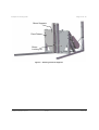
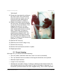
1
Icefield Instruments Inc.
tel: (867) 633-4264
#300-116 Galena Rd
fax: (867) 633-4217
Whitehorse, Yukon CANADA
e-mail: [email protected]
Y1A 2W6
web: http://www.icefield.yk.ca
User Manual for the
ECLIPSE Ice Coring Drill
Rev. 4c - 18 November 2012
Eclipse Ice Coring Drill
Page 2 of 75
Table of Contents
1
Assembly instructions ....................................................................................................4
1.1
1.2
1.3
1.4
1.5
1.6
1.7
1.8
2
Operating Instructions................................................................................................. 42
2.1
2.2
2.3
2.4
2.1
3
Drilling a straight hole...................................................................................... 48
Keeping the drill cold ....................................................................................... 49
Cleaning the drill.............................................................................................. 49
Keeping the drill clean ..................................................................................... 50
Over Night Storage.......................................................................................... 50
Setting the Anti-Torque Spring Tension ......................................................... 51
“Feeling” the drill.............................................................................................. 51
Cutter heel choice ........................................................................................... 51
Losing the lock pins ......................................................................................... 51
Drilling without a Cable Level Winder ............................................................ 51
Eclipse Ice Drill Optional Upgrades ........................................................................... 52
4.1
4.2
5
General Comments ......................................................................................... 42
Drilling Core ..................................................................................................... 44
Record keeping ............................................................................................... 46
Zero depth ....................................................................................................... 47
Encoder and depth counters ........................................................................... 47
Tips .............................................................................................................................. 48
3.1
3.2
3.3
3.4
3.5
3.6
3.7
3.8
3.9
3.10
4
General Notes ....................................................................................................4
Winch Frame Assembly .....................................................................................5
Level Winder Assembly .................................................................................. 13
Boom Assembly ............................................................................................... 14
Control Panel Connections ............................................................................. 15
Winch Cable Set-Up ....................................................................................... 21
Drill Anti-torque Section .................................................................................. 26
Drill Assembly .................................................................................................. 36
Long Boom Assembly ..................................................................................... 52
Wet drill modifications ..................................................................................... 55
Routine Maintenance of ECLIPSE Ice Drill ................................................................ 64
5.1
5.2
5.3
5.4
Honing the Cutters and Core Dogs ................................................................ 64
Storing the Drill for the Season ....................................................................... 64
Saline environments ........................................................................................ 64
Oil ..................................................................................................................... 65
Icefield Instruments Inc.
rev4c
Nov-12
Eclipse Ice Coring Drill
5.5
6
Level Winder Maintenance ............................................................................. 66
Troubleshooting .......................................................................................................... 66
6.1
6.2
6.3
6.4
6.5
6.6
6.7
6.8
6.9
7
Page 3 of 75
Drill motor will not start .................................................................................... 66
Winch motor will not start ................................................................................ 67
Depth counter runs in reverse......................................................................... 67
Drill motor is trying to rotate the barrel, but not working ................................ 67
Freeing a stuck drill ......................................................................................... 67
“Gum” in the sheave ........................................................................................ 68
Winch motor failure ......................................................................................... 68
Winch transmission failure .............................................................................. 68
The drill does not advance .............................................................................. 68
Tools and Spares ........................................................................................................ 70
7.1
7.2
7.3
Supplied Tools List .......................................................................................... 70
Suggested Tools List ....................................................................................... 71
Spare Parts Kit................................................................................................. 73
Icefield Instruments Inc.
rev4c
Nov-12
Eclipse Ice Coring Drill
Page 4 of 75
1 Assembly instructions
1.1 General Notes
•
Unless otherwise noted, all the hardware/fasteners on this drill are of Imperial
dimensions (fractional inches). Please refrain from using metric tools as damage
to the unit may result.
•
Many fasteners on this drill are secured using Loctite (a cyanoacrylate threadlocking compound). Red (permanent) Loctite is used, for example, on the screws
holding the plastic flights onto the inner barrel. Blue (removable) Loctite is used
on frame fasteners. If you suspect that a screw or bolt is not rotating because it
has this material applied to it, you can heat the part with a torch to soften the
locking compound. Take care not to damage plastic and/or rubber components.
•
Frame fasteners are all stainless steel – where they attach to load-bearing
aluminum parts, there is often a steel Helicoil® thread insert used to strengthen
the joint and to avoid thread wear on the aluminum. If you see evidence of
thread damage on a fastener (the inserts are harder than the fastener), please
replace the fastener as soon as possible.
•
Fasteners mating to Helicoil® inserts should be treated with anti-seize
compound (thread lubricant).
•
Assembling a large machine with many close-tolerance parts can be made much
easier if fasteners are left a bit loose until all the fasteners are in place.
Icefield Instruments Inc.
rev4c
Nov-12
Eclipse Ice Coring Drill
•
Page 5 of 75
Figure 1 below shows the general layout of the drill when assembled. The drill
shown consists of the short boom configuration in the horizontal position.
Top
Front
Figure 1 – Reference Frame
1.2 Winch Frame Assembly
In order to have a base onto which to assemble other component it is suggested that
the Winch Frame be assembled first.
Brake
Lever
Cable
Drum
Boom
Uprights
Pogo
Stick
Winch
Motor
Hand
Crank
Figure 2 – Winch Frame Assembly
Icefield Instruments Inc.
rev4c
Nov-12
Eclipse Ice Coring Drill
Page 6 of 75
1.2.1 Bare Frame Assembly
All frame components are stamped with letters to aid in assembly. Each component
should have a corresponding letter on each of its mating components.
Face
Frame
Diagonal
s
Winch Plate
Frame Base
Figure 3 – Bare Frame Assembly
First Assemble the Frame Base. This consists of two long base frame members and
one A frame block. The Face Frame can them be assembled and mounted to the frame
base. Next the diagonal frame members can be mounted. Lastly the Winch Plate can
be mounted to the back of the frame base.
1.2.2 Mounting the Cable Drum and Winch Motor
The winch motor and cable drum can now be mounted onto the frame. The input shaft
of the cable drum should be on the right side of the winch, as shown. Figure 4 shows
two chains installed. The right-hand chain (shown in foreground) is used to drive the
level winder. If the drill has no level winder, then omit this chain. The second chain (the
bottom is just visible in the photo) is for the hand crank. This second chain should
always be installed.
Icefield Instruments Inc.
rev4c
Nov-12
Eclipse Ice Coring Drill
Page 7 of 75
Figure 4 – Winch Cable Drum
Mount the winch Motor to the right diagonal frame member. Before tightening the
mounting fasteners for the winch motor attach the drive belt to the motor and drum.
Take care that the belt is not stretched and/or twisted when installed. The belt tension
should be such that about 5mm deflection results from modest thumb pressure. Also
ensure that the two pulleys are lined up so that the belt runs perpendicular to the
shafts.
Figure 5 – Installing the Drive Belt
Icefield Instruments Inc.
rev4c
Nov-12
Eclipse Ice Coring Drill
Page 8 of 75
Attach belt cover plate on the two posts attached to the winch motor using the supplied
thumb screws.
Figure 6 – Installing the Cover Plate
1.2.3 Mounting the Pogo Stick
Mount the Pogo stick to the frame base. Also mount the Pogo Supports. The pogo
supports can be lengthened or shortened by turning the support when its ends are held
in place. In this way the pogo stick can be stiffened if required.
Icefield Instruments Inc.
rev4c
Nov-12
Eclipse Ice Coring Drill
Page 9 of 75
Pogo Stick
Pogo Supports
Figure 7 – Pogo Stick Installation
1.2.4 Mounting the Boom Supports and Face Plates
Mount the Face Plates and Boom Supports to the front of the Face Frame. Also insert
the Boom Locking Pin into the bottom of the boom supports. It is suggested that this pin
be tied to the frame or another object using the supplied cord. This will avoid dropping
the pin down the drill hole or losing the pin.
Icefield Instruments Inc.
rev4c
Nov-12
Eclipse Ice Coring Drill
Page 10 of 75
Boom Supports
Face Plates
Boom
Locking Pin
Figure 8 – Installing the Boom Supports
Icefield Instruments Inc.
rev4c
Nov-12
Eclipse Ice Coring Drill
Page 11 of 75
1.2.5 Mounting the Hand Brake and Hand Crank
Attach the Brake Assembly (Brake caliper and Brake Handle attached with cable) to the
frame as shown in Figure 9. Attach the bearing blocks for the hand crank on the upright
members of the face frame. The Crank Shaft will have to be removed from one of the
bearing blocks pass the chain from the cable drum. It is recommended that the crank
handles only be installed if problems with raising the drill occur. The small gear on the
axle should be positioned to line up with the large gear on drum axle (next to the brake
disk).
Brake Handle
Hand Crank
Crank Handles
Brake Caliper
Figure 9 – Brake and Crank Installation
1.2.6 Mounting the Dummy Level Winder
The Level Winder Assembly is optional. If your drill does not come with a Level Winder
a Dummy Level Winder will be supplied. Secure the dummy level winder in its place on
the diagonal supports of the frame using the 3/8” spring pins provided. The semi-
Icefield Instruments Inc.
rev4c
Nov-12
Eclipse Ice Coring Drill
Page 12 of 75
circular cover over the level winder serves to support the winch cable, and maintain
tension on that cable when the mast is in the “down” position.
Figure 10 – Dummy Level Winder
Icefield Instruments Inc.
rev4c
Nov-12
Eclipse Ice Coring Drill
Page 13 of 75
1.3 Level Winder Assembly
The Level Winder Assembly is optional. If your drill does not come with a level winder
skip to the next section.
The Level Winder Accessory Module for the Eclipse II Ice Coring Drill System’s winch
provides is a virtually self-contained mechanical system for evenly wrapping
electromechanical cable onto the drum of the Eclipse II winch. The Level Winder is
shipped fully assembled, lubricated, and ready for installation.
Level Winder
Input
Sprocket
Drum
Input Side
Figure 11 – Installation of Level Winder
Ensure that the drive-chain for the Level Winder has been previously attached to the
winch drum at the input side. If not in place already, some disassembly will be required
to fit it now.
Mounting the Level Winder onto the frame is best done with two people. Lift the level
winder into place, and tip the chain sprocket end downward to loop the drive chain over
the input sprocket. Then mount the Level winder in place using the supplied 3/8” X 2”
spring pins. Note mounting nuts and bolts may be provided with the drill. If so these can
be used to secure the level winder, but it is suggested that spring pins are used to
locate one side of the level winder to allow for movement between the level winder and
Icefield Instruments Inc.
rev4c
Nov-12
Eclipse Ice Coring Drill
Page 14 of 75
frame.
1.4 Boom Assembly
This section outlines the assembly of the standard boom configuration. If your drill has
a long boom configuration refer to section 4.1.
Cradle
Hinged
Cradle
Boom
Pivot Pin
Boom Stop
Bracket
Pogo
Catch
Sheave
Figure 12 – Short Boom Assembly
Mount the Boom onto the frame using the Boom Pivot Pin. The Boom Pivot Pin is
secured with a supplied hairpin style cotter pin.
Mount the Boom Stop Bracket at the back end of the boom as shown in Figure 12. Do
not over tightening the mounting screws for the bracket. This will deform the boom and
cause interference with the sheave.
Mount the cradles as shown above. The hinged cradle is located closer to the sheave.
Also mount the Pogo Catch as shown. Ensure that it is properly located to catch the
pogo stick and prevent the boom from swinging into a vertical position.
Icefield Instruments Inc.
rev4c
Nov-12
Eclipse Ice Coring Drill
Page 15 of 75
1.5 Control Panel Connections
There are four electrical cables provided. They are the AC Power Cable, Winch Frame
Cable, Winch Motor Cable, and Mast Cable.
Figure 13 – Control Panel Back Panel
Figure 13 above shows the back panel of the control panel. This is where all of the
electrical cables are plugged into the control panel (the exact look of the back panel
might differ).
Icefield Instruments Inc.
rev4c
Nov-12
Eclipse Ice Coring Drill
Page 16 of 75
Mast Cable
Connectors
Winch Frame
Cable Connectors
Winch Motor
Cable Connector
Figure 14 – Drill Cable Connection Locations
1.5.1 AC Power Cable
The AC Power Cable is blue and yellow in color. It has a 3 socket mil connector at one
end and is blank at the other. The blank end of the cable must be terminated with the
style of 230V plug that is required for the type of power source (ex, diesel generator)
used by the user. The AC power cable is connected to the control panel and the power
source to be used.
Wiring of the mains power cables is as follows:
Pin
Colour
Function
A
Black
Hot
C
White
Neutral
B
Green
Frame Ground
Icefield Instruments Inc.
rev4c
Nov-12
Eclipse Ice Coring Drill
Page 17 of 75
1.5.2 Internal Drill motor wiring
Internal to the drill (e.g., between the drill motor assembly and the bottom of the antitorque section), and at the spline coupling on the winch drum shaft, the wiring is as
follows:
The cable plug is an MS3116F8-4S (or MS3116E8-4S if there is no strain relief)
connecting to an MS3112E8-4P receptacle.
Pin
Function
A
Drill Power
D
Drill Return (ground). This pin is also connected to the drill wireline armour
and the entire frame of the drill system.
B
Tachometer signal
C
Tachometer return (ground) *
* For drills build in 2012 and later, this pin is connected (shorted) to the drill system
frame at the connected located at the bottom of the anti-torque section. These drills use
a high-pressure Regal bulkhead that has only three pins.
1.5.3 Regal (pressure bulkhead) wiring:
Regal part number 6100 is equivalent to an MS3116E8-33P, which mates with an
MS3116F8-33S or MS3116E8-33S.
Pin
Corresponding connector in the
MS311x-8-4S/P drill motor wiring
Function
A
A
Drill Power
B
C and D
Drill Return and Tachomoter Return
(ground). Also connected to the drill
system frame.
C
B
Tachometer signal
1.5.4 Winch Frame Cable
The Winch Frame Cable is black, has a small 8 socket connector at one end and two
mil connectors at the other end. The two connectors at the other end are a 2 socket
Icefield Instruments Inc.
rev4c
Nov-12
Eclipse Ice Coring Drill
Page 18 of 75
and a 4 socket. The 4 socket connector is connected to the axle of the drum connector,
and the 2 socket connector is connected to the bottom side of the top frame cross
member as shown in Figure 14.
The winch frame cable connects the control box to the winch drum and emergency stop
switches. . The plug at the control box is an MS3116F12-8P mating with an
MS3112E12-8S receptacle. The plugs on the other end of this “two-headed” cable are
noted in the table.
Pin (8-pin)
Pin (at device)
Function
A
N/C
G
C (MS3116F8-4S)
Tachometer return
(ground)
B
B (MS3116F8-4S)
Tachometer signal
H
N/C
E
A (MS3116F8-2S)
Emergency Stop
F
Emergency Stop
C
B (MS3116F8-2S)
A (MS3116F8-4S)
D
D (MS3116F8-4S)
Drill return (ground)
Drill power
1.5.5 Winch Motor Cable
The Winch Frame Cable is the shortest and thickest black cable. It has a large 8 socket
connector at each end. One end is connected to the control panel and the other to the
winch motor.
The winch cable connects the control panel to the brake/tachometer housing on the
winch motor (cable plugs MS3116F16-8P/S mating with receptacles MS3116E168P/S).
Pin
Function
A
Tachometer signal
B
N/C
G
Tachometer Ground
Icefield Instruments Inc.
rev4c
Nov-12
Eclipse Ice Coring Drill
Page 19 of 75
Pin
Function
F
Brake solenoid
C
Brake Solenoid
E
Winch Power
D
Winch Return
H
N/C
Frame
Ground
1.5.6 Mast Cable
The Mast cable is the longest one. It has a 8 socket connector at one end that is
connected to the control panel. The other end has one yellow lead and one black one.
The yellow lead is connected to the limit switch at the top of the boom. The black lead
is connected to the encoder located on the sheave. Velcro straps are provided to
secure the cable to the mast. Ensure that all cables are secured so as to not get
damaged during drill operation.
Limit Switch
Velcro Strap
Encoder
Figure 15 – Mast Cable Connections
Icefield Instruments Inc.
rev4c
Nov-12
Eclipse Ice Coring Drill
Page 20 of 75
The mast cable connects the control box to the encoder and drill stop switch. The plug
at the control box is an MS3116F12-8P mating with an MS3112E12-8S receptacle. The
plugs on the other end of this “two-headed” cable are noted in the table.
Pin (8-pin)
Pin (at device)
Function
A
B (97-3106A-14S-6S)
Encoder +12VDC
G
A (97-3106A-14S-6S)
Encoder Ground
B
E (97-3106A-14S-6S)
Encoder A-channel
H
D (97-3106A-14S-6S)
Encoder B-channel
E
2 (Molex 1200650255)
Mast stop switch
F
1 (Molex 1200650255)
Mast stop switch
C
N/C
D
N/C
Icefield Instruments Inc.
rev4c
Nov-12
Eclipse Ice Coring Drill
Page 21 of 75
1.6 Winch Cable Set-Up
Before the winch cable is terminated at the drill (as described in section 1.7), it is
recommended that the winch cable be routed through the drill. If a Level winder is
included, it is also suggested that the level winder be synchronized with the cable on
the drum.
1.6.1 Level Winder Synchronization
If a level winder is provided with the drill, it is important that it be synchronized with the
cable on the Winch Drum.
With the cable wrapped onto the drum (if necessary, tidy this up manually) apply
electrical power to the winch drive and slowly pay-out a small length of cable from the
drum while noting in which direction the shuttle is moving.
Caution: ensure that the cable is secure so that a large amount of cable does not
spring from the drum.
Gear Housing
Cover Plate (Shown
Transparent)
Gear Securing
Screw
Figure 16 – Level Winder Assembly, Gear Side
Remove the gear-housing cover plate. Loosen, but do not remove the socket head cap
screw at the center of the large gear (Figure 16). This allows the reverser screw to
rotate independently of the gear.
Icefield Instruments Inc.
rev4c
Nov-12
Eclipse Ice Coring Drill
Page 22 of 75
With everything else stopped, rotate the reverser-screw by inserting a hex-wrench into
the socket head cap screw on the idler side of the reverser screw (Figure 17 below).
Rotate the reverser screw to move the gap between the Level Winder Fairlead Rollers
directly above the winch cable and so that the Level Winder Shuttle is moving in the
same direction as the Winch Cable.
Level Winder
Fairlead Rollers
Socket Head
Cap Screw
Level
Winder
Figure 17 – Level Winder Assembly, Idler Side
Once set, lock the synchronization by holding the reverser screw at the non-gear end
with a hex-wrench, while tightening the hex-socket bolt at the gear end. Replace the
gear-box cover plate.
After the initial (loosely wound and disturbed) cable has been spooled out, it may be
necessary to re-synchronize the LWM, but this should only amount to a small positional
adjustment.
Icefield Instruments Inc.
rev4c
Nov-12
Eclipse Ice Coring Drill
Page 23 of 75
1.6.2 Routing the Winch Cable
Using the control panel slowly turn the winch cable drum in the (down position) to dole
out a few meters of cable. Caution: ensure that the cable is secure so that a large
amount of cable does not spring from the drum.
Sheave
Wheel
Level Winder
Fairlead Rollers
Winch Cable
Routing
Cable
Retaining
Spring
Figure 18 – Winch Cable Routing
Route the winch cable as shown in Figure 18 above. The cable is routed through the
Fairlead rollers on the level winder (if a level winder is included with the drill). The
winch cable is also routed over the level winder cover (or dummy level winder cover)
and around the Sheave Wheel. Ensure that the cable is secure in the groove of the
Sheave Wheel and held in place by the Cable Retaining Spring.
Icefield Instruments Inc.
rev4c
Nov-12
Eclipse Ice Coring Drill
Page 24 of 75
1.6.3 Routing the Winch Cable if Cable is Already Terminated
It is suggested that the winch cable be route through the Level Winder and Sheave
before terminating the cable at the drill (as described in section 1.6.2). If the cable has
already been terminated it is still possible to route the winch cable.
Bearin
g
Figure 19 – Fair Lead Bearing Blocks
The cable can be routed through the Fairlead Rollers in the Level Winder by loosening
the two pairs of bolts which hold the two bearing blocks at the ends of the rollers
(Figure 19). These bearing blocks are also held in place by a pair of short (hidden)
dowel pins which accurately locate the blocks. It is possible to loosen the innermost
blocks’ bolts enough to lift the block off of the dowel pins, and tilt it enough to free the
front block and one of its rollers. Disassembled this far, it is possible to thread the cable
into the slot and reassemble the fairlead roller unit.
Icefield Instruments Inc.
rev4c
Nov-12
Eclipse Ice Coring Drill
Page 25 of 75
Top End
Block
End Block
Fasteners
Figure 20 – Sheave Top End Block
The winch cable can be routed onto the Sheave Wheel by removing the four Fasteners
holding the Sheave Top End Block (see Figure 20). This will allow the top end block
with the Sheave Spring attached to be removed and the cable to be routed onto the
wheel.
Icefield Instruments Inc.
rev4c
Nov-12
Eclipse Ice Coring Drill
Page 26 of 75
1.7 Drill Anti-torque Section
Anti-torque
Spring Pins
Hammer
Retaining Spring
Loaded Pins
Hammer
assembly
Slipring Pin
Slipring Assembly
Screws
Slipring
Assembly
Figure 21 – Anti-torque Assembly
1.7.1 Winch Cable Termination
Warning: before the winch cable is terminated ensure that the winch frame cable is
unplugged!
Before terminating the winch cable the winch cable should be passed through the level
winder and sheave assemblies as described in section 1.6.2.
The winch cable termination mechanism is inside the anti-torque section of the drill.
The termination is a pinch-type termination located inside the hammer
To attach the winch cable to the drill, the hammer assembly must first be removed from
Icefield Instruments Inc.
rev4c
Nov-12
Eclipse Ice Coring Drill
Page 27 of 75
the anti-torque section. First remove the anti-torque spring pins near the top of the antitorque assembly, and using a large flat head screw driver remove the six slip ring
assembly screws (see Figure 21). The slip ring assembly can now be removed. The
hammer can also be removed from inside the anti-torque tube. There are three springloaded pins that must be retracted in order to release the hammer. Hammer Pin
Retraction tools are provided to make this easier.
Figure 22 – Hammer Pin Retraction Tool
Icefield Instruments Inc.
rev4c
Nov-12
Eclipse Ice Coring Drill
Page 28 of 75
Remove the hammer flange from the lower end of the hammer that contains the
Evergrip termination. Thread the cable through the upper anti-torque assembly and the
hammer and attach the cable to the Evergrip termination according to the
manufacturers' instructions.
Evergrip
Termination
Hammer
Flange
Figure 23 – Hammer Assembly
The termination kit is the Evergrip part number P/N 9006120-1, and the re-termination
kit (does not include the body) is 9006120-1R. Installation instructions are i9ncluded
with each re-termination kit, but more information is available on the PMI website:
www.pmiind.com/index.php?id=23.
Icefield Instruments Inc.
rev4c
Nov-12
Eclipse Ice Coring Drill
Evergrip
Housing
Page 29 of 75
Evergrip
Central “Egg
Evergrip
Locking Nut
Hammer
Flange
Figure 24 – Cable Grip Assembly
The two small holes in the base of the hammer can be used (together with the two pins
(Allen keys) supplied with the Evergrip termination kit) as a wrench to tighten the overwraps onto the central “egg” (see pictures above). Make sure that while you are
tightening the “egg”, the flange does not bottom out on the Evergrid housing, thereby
giving you a false sense of having tightened up the egg.
Leave about 10cm of winch cable conductors below the hammer for electrical
termination. The strands of the cable armor should be cut off immediately below the
termination and wrapped in tape to protect the conductors. The easiest way to cut the
strands is using a Dremel tool with a parting disk, as shown in Figure 25.
Icefield Instruments Inc.
rev4c
Nov-12
Eclipse Ice Coring Drill
Page 30 of 75
Figure 25 – Winch Cable Preparation
When reassembling the hammer, make sure the 6mm (1/4”) clearance hole in the
flange and the corresponding hole in the hammer body are lined up – this hole accepts
the pin on the slipring assembly that is attached to the bottom hinge block of the antitorque section.
6-32 Grounding Bolt
Locations
¼” Clearance
Hole for
Slipring Pin
10cm of the Cable’s Central
Conductors Should Extend
from Here, but No Armor
Figure 26 – Hammer Flange
Icefield Instruments Inc.
rev4c
Nov-12
Eclipse Ice Coring Drill
Page 31 of 75
1.7.2 Slipring Wiring
Ground Wire
Seacon Waterproof
Connectors (Male)
Slipring Pin
Figure 27 – Slipring Wiring
After the winch cable has been terminated using the Evergrip termination kit, the
electrical connection of the winch cable can be completed. The winch cable is
electrically connected to the top of the slipping assembly. The picture above shows the
slipring assembly. Three male Seacon waterproof connectors and one black grounding
lead are used to complete the connections.
Icefield Instruments Inc.
rev4c
Nov-12
Eclipse Ice Coring Drill
Page 32 of 75
The table below outlines the connections that need to be made. The female Seacon
connectors need to be soldered to the appropriate Winch cable conductors. The female
Seacon connector used for the drill power is soldered to two winch cable conductors.
Winch Frame
Cable
Connector
Function
Slip Ring Wire
Colour
Cable Conductor
Colour
A
Drill power (uses two
conductors!)
Red
Red and White
B
Tachometer signal
White
Green
C
Tachometer return
Green
Black
D
Drill power return
Black
Ring Terminal to
Hammer
The connections made between the winching cable strands and the drill sonde’s
slipping are NOT in a watertight compartment. Voltages on the A/D circuit (drill motor)
will reach up to 200VDC during drill operation. Make sure that you insulate the
connections appropriately for your drilling conditions!
Icefield Instruments Inc.
rev4c
Nov-12
Eclipse Ice Coring Drill
Page 33 of 75
1.7.3 Verifying the Slipring Wiring (Test Box)
Since the slipring electrical connections are difficult to access, and the centre
conductors of the wireline cable are not colour-coded, it is suggested that these
connections be verified before the drill is reassembled. A wire tester box has been
provided for this purpose (see Figure 28). Note that the tester box might be white or
black.
Female Four Pin
Mil Connector
Male Four Pin
Mil Connector
Lead Test Points
Figure 28 – Wire Tester Box
Icefield Instruments Inc.
rev4c
Nov-12
Eclipse Ice Coring Drill
Page 34 of 75
Winch Frame
Cable Connector
Figure 29 – Winch Cable Connector Location
The female connector is attached to the winch frame cable connector located on the
axle of the drum assembly (see Figure 29 above).Each circuit can be selected using
the center switch. For each selected circuit the red LED will light up if the circuit is
complete.
In order to select the correct conductor from the four inside the wireline cable, connect
the test box to the winch frame cable connector. Then select each circuit (a, B, C, and
D) in turn. For each selection, touch the bare end of each wire to the screw next to the
circuit lable (e.g., “A”). If you have selected the correct conductor, the LED will
illuminate. Keep in mind that two of the internal wireline conductors are connected to
circuit “A”, and that the wireline armour is connected to circuit “D”. At the slipring, circuit
“D” uses a separate ground wire (see Figure 27 – Slipring Wiring).
As a final check after the slipring connections have been completed, the anti-torque to
drill motor jumper (located at the bottom of the slipring assembly can be plugged into
the test male connector on the top of the Wire Tester. Select each circuit in turn to
verify connections. Note also that circuits C and D (ground returns for drill tachometer
and drill motor) are connected together (see section 1.5.3)
Icefield Instruments Inc.
rev4c
Nov-12
Eclipse Ice Coring Drill
Page 35 of 75
1.7.4 Re-Assembly
After the cable termination and wiring has been completed, the anti-torque assembly
can be re-assembled. Make sure that the slip ring pin is lined up with the clearance
hole in the hammer assembly.
The anti-toque section can then be reassembled to the drill motor section. Firstly
connect the Anti-torque to Drill motor Jumper.
Figure 30 – Anti-Torque to Drill Motor Jumper Cable
Insert the Anti-torque bottom block into the pressure housing of the drill motor
assembly. Secure the assembly using the six drill assembly screws provided.
Anti-Torque
Assembly
Drill Assembly
Screws
Drill Motor
Connector
Drill Motor
Assembly
Figure 31 – Anti-Torque and Drill Motor Assembly
Icefield Instruments Inc.
rev4c
Nov-12
Eclipse Ice Coring Drill
Page 36 of 75
1.7.5 Anti-Torque Spring Adjustment
Lock Nuts
5/16” Pins
Figure 32 – Anti-Torque Spring Adjustment
After the anti-torque section is reassembled the anti-torque spring tension can be
adjusted, and locked. The desired tension is depended on the ice and drilling
conditions. This is further discussed in section 3.6. Use the two provided 5/16" pins and
the two lock nuts at the top of the drill to adjust and lock in place the spring tension.
1.8 Drill Assembly
Cutter
Head
Inner
Barrel
Outer Barrel
Drill Motor Assy
Anti-torque
Figure 33 – Drill Assembly
Icefield Instruments Inc.
rev4c
Nov-12
Eclipse Ice Coring Drill
Page 37 of 75
1.8.1 Outer Barrel
Assemble the drill motor section and anti-torque section as detailed in the sections
1.7.4. Place these two assemblies on top of the boom and secure them using the
cradle. Slide the outer barrel over the drill motor section. This is best done by two
people as this is a tight fit.
Drill Motor Assy
Cradle
Outer Barrel
Drill Assembly
Screws
Strap Wrench
Figure 34 –Positioning the Outer Barrel
There are stamped numbers on both the outer barrel and the drill motor section that
indicate the orientation of the two components. The supplied strap wrenches can be
used to facilitate turning the outer barrel into position. Once positioned, secure the
outer barrel using six drill assembly screws.
Icefield Instruments Inc.
rev4c
Nov-12
Eclipse Ice Coring Drill
Page 38 of 75
Orientation
Markings
Figure 35 –Outer Barrel Orientation Markings
1.8.2 Inner Barrel
Core Plug
Capstan
Inner Barrel
Corelocks
Locating
Pins
Figure 36 – Inner Barrel Assembly
Icefield Instruments Inc.
rev4c
Nov-12
Eclipse Ice Coring Drill
Page 39 of 75
Insert the Core plug into the inner barrel. This core plug serves to separate the ice core
from the chips that are dumped on top. The core plug must always be present when
drilling.
The inner barrel is attached to the capstan by three locating pins and three corelocks
(see image above). Slide the inner barrel into the Outer barrel turn the inner barrel until
the locating pins line up with the notches on the inner barrel. (Caution: the cutters are
very sharp! Protect your hands from the cutters)
Figure 37 – Engaging the Corelocks
Using the control panel turn the drill slowly until the three sockets for the corelocks are
accessible from the three access ports in the outer barrel. Use the provided ¼” driver to
push and turn the three corelocks into their lock position.
Icefield Instruments Inc.
rev4c
Nov-12
Eclipse Ice Coring Drill
Page 40 of 75
1.8.3 Installing and removing the cutter head
The fit between the cutter head and the inner barrel is very tight. Generally, the head
should be installed once at the start of the drilling project and removed only at the end
when the drill is packed up. Before installing heels and cutters, you can use the deadblow hammer to GENTLY tap the head onto the barrel. Make sure that the head does
not get cocked sideways. The objective it to ensure that the three locking screws line
up precisely with the three holes on the inner barrel.
Locking
Screws
Figure 38 - Installing the Cutter Head
If you are having trouble, you can immerse the cutter head in hot or boiling water – this
will expand the aluminum head and will loosen the fit temporarily. If you use this
technique, you must somehow dry the head to remove water that might gum up the
core dogs during drilling.
To remove the head, disengage the three locking screws, and the gently tap the top
side of the spiral flutes with a dead blow hammer and provided nylon rod. Knock each
flute once, and then move to the next flute. Do not let the head become cocked on the
inner barrel (this will stretch the head permanently) and do not strike the plastic
flights on the inner barrel.
A dead-blow hammer is a plastic or hard rubber hammer filled with sand or lead shot.
Never use a metal hammer on the cutter head!
Icefield Instruments Inc.
rev4c
Nov-12
Eclipse Ice Coring Drill
Page 41 of 75
1.8.4 Installing heels and cutter teeth
The three cutters and heels are stacked on pairs of pins on the cutter head. The fit is
tight, but this is intentional so that the cutters and heels stay in place.
The heels serve to limit the depth of cut. The heels are numbered and you should
always drill with all three heels of the same number. The number represents the
nominal cutting distance per revolution in mm. In other words, #4 heels permit up to
4mm of cutting per revolution, although in practice, the cut is shallower.
Cutter Heal
Cutters
Locating
Pins
Spring Slot
Core Dogs
Core Dog
Pivot Lock
Core Dog
Springs
Figure 39 – Cutter Head
1.8.5 Installing the core dogs and springs
The core dogs serve two purposes: they keep the core from falling out of the drill, and
they break the core when the drill is raised. Weaker Core Dog Springs should be used
when drilling in firn (to avoid the dogs “milling” the core). When one drills through the
firn-ice transition, stronger spring need to be installed.
To install springs, loosen the core dog pivot lock (a recessed set screw on the bottom
of the cutter head as shown in Figure 39). Retract the pivot pin enough so that only one
side of the core dog is on the pivot.
Flare the spring so that one arm engages the slot in the head and the other lays on the
Icefield Instruments Inc.
rev4c
Nov-12
Eclipse Ice Coring Drill
Page 42 of 75
back of the core dog. Press the spring into the slot until the coil of the spring is lined up
with the pivot – with your other hand, press the pivot through the spring and core dog.
Secure the pivot lock set screw.
If you lose a spring, or need one with different strength, it is possible to make them in
the field by wrapping spring wire around a mandrel such as a drill bit. See Figure 40.
Figure 40 – Fabricating Core Dog Springs
Note that the ends of the spring should drop into the spring slot on the cutter head – it
is important that the spring does not protrude and get caught on the sidewalls of the
hole.
2 Operating Instructions
2.1 General Comments
2.1.1 Motor speeds
The drill motor should be run at 3750rpm which will result in a 75rpm cutter head
speed. The winch motor should be run at a maximum speed of 3000rpm. If more torque
is required for hauling, the smaller drive gear can be put on the motor rather than on
the winch drum input shaft.
2.1.1.1 Winch motor
When breaking core, it is possible that the winch motor does not have sufficient torque.
In this situation, the hand crank can be used to help the winch motor break the core.
WARNING! Take care that you do not get tangled in the crank when the winch begins
to turn!
Icefield Instruments Inc.
rev4c
Nov-12
Eclipse Ice Coring Drill
Page 43 of 75
2.1.1.2 Drill motor
The tachometer on the drill motor can read incorrectly because the pulse from the
magnetic pickup can get lost in the drill motor commutation noise. Sometimes, the
tachometer reads a high speed when the motor is, in fact, running slower. The normal
operating setting is about 70 on the drill motor speed control.
2.1.2 Winch setup
Make sure that the mast locking pin (3/4” diameter aluminum with handle) is tethered to
the winch frame. YOU DO NOT WANT THIS PIN TO DROP INTO THE HOLE!!!
Solar radiation can cause the winch frame to sink into the ground. To prevent this, you
may want to do the following:
•
Clear off loose snow to expose a solid surface for the winch
•
Place pieces of plywood under the frame
2.1.3 Drill trench
Unless the long boom option has been included with the drill, a 1.5m deep trench is
required into which the drill can swing. Because the main legs on the winch are splayed
out, the trench does not have to be cut very carefully, but you should try to keep it
about the same width as your shoulders. The trench should be fitted with steps as
access to the trench is required during drilling.
You may want to arrange a removable cover for the trench, both for safety and
cleanliness.
It is also suggested that the sides of the trench be reinforced with plywood or beams to
help support the drill and to prevent erosion of the sides of the trench.
2.1.4 Trap door
It is strongly recommended that once a hole is started, a trap door be fitted over the
hole so that the hole can be covered when the drill is at the surface (the trap door can
be operated from the surface with a string).
If something is dropped into the hole, then the provided magnet can be used to attempt
retrieval. The core locks are made out of magnetic stainless steel.
The trap door can be fashioned from a piece of plywood with hinges made of fabric or
leather straps. Ice screws or nails can secure the straps onto the ice or snow.
Icefield Instruments Inc.
rev4c
Nov-12
Eclipse Ice Coring Drill
Page 44 of 75
2.1.5 Jammed Core Locks
If, during drilling, it becomes difficult to remove a core lock, it may be that snow/chips
have packing into the hole. A small amount of anti-freeze will un-stick the lock.
2.1.6 Cautions
•
ALWAYS start the drill or winch motors with the speed control set to zero.
Starting the motor with higher speed settings may damage the electrical motor
and/or the power system.
•
Be aware of rotating components in and around the winch and drill.
•
The cutting teeth are very sharp and will easily cut clothing and skin.
2.2 Drilling Core
When drilling there is a plastic core plug that floats freely inside the core barrel. This
core plug serves to separate the ice core from the chips that are dumped on top. The
core plug must always be present when drilling.
To drill core, follow the following procedure:
1. Raise the mast with the drill attached. Reset master depth counter to zero.
2. Insert the mast locking pin. This ¾” diameter aluminum pin should be tethered to
the winch frame.
3. Ensure cable is tight and the spring-loaded sheave is seated in the top of the
mast (if the mast stop switch is engaged, you will not be able to run the winch
motor "UP" - back the drill off slightly).
4. Release the drill clamp and open the trap door.
5. Set the winch speed to zero (this should be done before each trip into the hole),
and start the winch motor in the "DOWN" direction with the speed set to zero.
6. When the proper depth is reached (about 50cm above the hole bottom), start the
drill in the "FORward" direction and run the speed up to 3750 rpm. Slowly lower
the drill until cutting starts (you can see this happen as the drill motor draws
more current). You should be able to drill 90-100cm in ice (more in firn) before
the drill motor stalls and the current rises. The operator must respond quickly to
reduce motor voltage when stalling occurs. The drill motor should not receive
more than 2A. Until the anti-torque section is below the surface, the anti-torque
action will have to be provided by a human standing in the drill trench. The
reason it is important to start drilling before the drill touches bottom is that
Icefield Instruments Inc.
rev4c
Nov-12
Eclipse Ice Coring Drill
Page 45 of 75
otherwise there is a risk that “fluff” gets caked onto the bottom of the heels,
thereby preventing the cutters from advancing the drill (see notes in
troubleshooting section)
7. Push the "MAX DEPTH" button to hold this depth reading.
8. Stop the drill motor and raise the winch slowly. You should be able to
hear/feel/see the core break (except in fragile ice which breaks easily). If the
winch motor cannot break the core on its own, you can use the hand crank to
assist. For safety’s sake, make sure to remove the crank(s) before moving to
high speed.
9. Raise the drill (max speed on winch motor is 3000 rpm). Slow down as the
surface is reached - the winch will stop when the drill trips the mast stop switch.
10. Close the trapdoor (you have one,
correct?)
11. Remove the mast lock pin and
lower the tower onto the locking
pogo stick. WARNING! Before
lowering the mast, check that you
do not have a “hanger.” A hanger is
a section of ice core that is
dangling out the front of the drill.
This can happen if the core dogs
slip a bit before they manage to
grab onto the core. A hanger must
be pushed up into the drill by
someone who descends into the
drill trench – otherwise, there is a
risk that the core gets snapped off
and falls into the hole.
12. Remove the inner barrel core locks
– this is done by slowly rotating the
drill barrel to the three positions that
expose the core locks through the
access hole in the outer barrel. The
core locks are removed by pressing
in using the 1/4” square drive tool
and rotating 1/4 turn. PLACE THE
CORE LOCKS IN A SAFE PLACE
WHERE THEY WILL NOT FALL IN
Icefield Instruments Inc.
rev4c
Nov-12
Eclipse Ice Coring Drill
Page 46 of 75
THE HOLE!
13. Extract the inner barrel by pulling on
the cutter head. If the inner barrel
does not come out easily, you can
knock on the outer barrel with a
dead-blow hammer to release it.
14. Shake out the chips located above
the core plug. The chips are shaken
out the top of the inner barrel. If the
chips to not come out, you can
CAREFULLY tap the inner barrel
with a dead-blow hammer to release
them. It can help if you place a
screwdriver or dowel through the
parallelogram-shaped holes – this
will prevent the core plug (and the
ice core itself!) from flying out of the
barrel. The chips can be collected for
analysis (e.g., pollen)
15. Remove the core plug
16. Slide the core out into a bag or tray
17. Reinsert the core plug
18. Reinsert the inner barrel and lock it in place
19. Repeat procedure!
2.3 Record keeping
With each run, you should record the following:
•
The run number (increment each time, even if no core is recovered)
•
The “up” direction and run number on the bag into which the core is placed.
•
Maximum depth reached.
•
Length of core recovered.
•
Whether the core had a “flange.” A flange is a flaring at the bottom of the core
that indicates that the core has broken off right to the bottom of the hole (i.e., it
has broken just below where the cutter stopped cutting. This is VERY important
Icefield Instruments Inc.
rev4c
Nov-12
Eclipse Ice Coring Drill
Page 47 of 75
because it means that the cumulative core length and depth counter must match
at this depth.
This information is necessary to measure core recovery (generally very close to 100%
with the ECLIPSE drill) and to make corrections for the depth counter (cable stretch,
slippage, etc.)
You may also want to record the weight of the core, number of pieces recovered, etc.
2.4 Zero depth
We strongly recommend that you use the mast stop switch as your zero depth
reference. This way, you can push the depth reset button (to make sure the counter is
at zero) when the drill hit the mast stop switch. Later, you can add/subtract the constant
offset between the cutters and the ice surface from all the depth readings. There is too
much chance for human error if you try to do this another way in the field.
2.1 Encoder and depth counters
The encoder supplied produces 512 ppr. The circumference of the cable when lying on
the sheave is approximately 90.78cm, so the conversion factor to compute cm/pulse is
0.1772. You may wish to check this conversion factor by performing a calibration. The
conversion factor of 0.1772 has been programmed into both counters.
Slave Counter
Icefield Instruments Inc.
Master Counter
rev4c
Nov-12
Eclipse Ice Coring Drill
Page 48 of 75
Figure 41 – Control Panel
The two depth counters serve different functions. The master counter is located under
the "DEPTH RESET" button and records the current position of the drill; the slave
counter is under the "MAX DEPTH" button.
The Master Counter is reset by pressing the Depth Reset Button. The Slave Counter is
reset by pressing the Menu and Reset buttons on the key pad of the counter. The slave
counter (Yokogawa) can be used to "lock" the current position of the drill by pushing
the "MAX DEPTH" button (this button normally causes the counter display to hold).
3 Tips
The following are general tips for drilling and drill operation.
3.1 Drilling a straight hole
Good drilling is a bit of an art. There are several tradeoffs:
•
You want big chips to make chip transport efficient (i.e., aggressive cutting)
•
You want good quality core with no cracks (i.e., gentle cutting)
•
You want a straight, vertical hole, which means you have to use the sonde as a
Icefield Instruments Inc.
rev4c
Nov-12
Eclipse Ice Coring Drill
Page 49 of 75
pendulum to find the vertical. If you let all the weight of the sonde rest on the
cutters, you will lose the pendulum effect and the hole will eventually curve off to
the side.
•
You want the anti-torque springs to be tight enough to prevent rotation, yet not
so tight that they do not allow the drill to descend easily.
Generally, the weight of the drill is just about right to provide the correct drilling
pressure. Nevertheless, the “pressure on bit” will change depending on whether the
winch transmission is warm (cable pays out more easily) and the depth of drilling.
Changing ice conditions also mean that different amounts of drill pressure are
necessary (for example, in brittle ice (found at 100-150m), you need to reduce pressure
to minimize cracking the core.
The best technique for the ECLIPSE drill seems to be to set the winch to pay out cable
(but with the speed set to zero, or almost zero) and then to use the hand brake to
control the drilling speed, as necessary.
Under some conditions, you can leave the winch in the “UP” position while drilling,
thereby applying a bit of tension to the cable and allowing the drill to pull cable off the
winch.
3.2 Keeping the drill cold
The ECLIPSE drill works best when it is cold (below freezing) and dry. Water can
freeze on drill components, and will tend to gum up the free movement of cuttings.
The sun is your enemy! When the drill is on the surface, solar heating of the drill is
rapid. The first place you will notice melting is over the motor section where there is
heat liberated by the drill motor.
There are a number of techniques to keep the drill cold:
•
Drill at night or, at least, avoid drilling during the heat of the day.
•
Drill under cover, or at least arrange a tarpaulin to shield the sonde from the
sun’s rays.
3.3 Cleaning the drill
We strongly suggest that at the beginning of each season, a short (10m or so) hole be
drilled to test out the system and “scrub” the inside of the drill clean. Snow makes an
excellent scrubbing powder! The core from this initial hole can be discarded.
Icefield Instruments Inc.
rev4c
Nov-12
Eclipse Ice Coring Drill
Page 50 of 75
3.4 Keeping the drill clean
While drilling, care should be taken to ensure that the flights are cleaner after every
run. Any chips stuck on the flights of the inner barrel will impede the free movement of
chips while drilling and will result in poor performance. Use the dead-blow hammer
(carefully!) and a stiff bristle brush to keep the inner barrel spotless!
It is also important to keep the cutter head clean. At each run, the core dogs should be
inspected to ensure that they can swing freely (otherwise you may not be able to
retrieve the core you cut!)
A clean, dry drill is a happy drill!
3.5 Over Night Storage
Frost tends to form in the drill overnight, impeding early-morning operation (the added
drag seems to prevent normal chip-transport). To avoid this problem, the last core
drilled in the day can be left in the drill and the drill stored at 15-20m depth (below the
winter cold wave) overnight. In the morning, the drill is raised to the surface and the
core removed - this will ensure that the barrel is clear of frost.
Icefield Instruments Inc.
rev4c
Nov-12
Eclipse Ice Coring Drill
Page 51 of 75
3.6 Setting the Anti-Torque Spring Tension
The anti-torque springs need to be adjusted so that they are tight enough to prevent the
drill from rotating when the cutters engage the ice. Generally, the springs need to be
tighter in firn than they do in ice. If the springs are too tight, they may prevent the drill
from descending easily – you can judge this when you are lowering the drill.Springs
that are too loose in firn will “windmill” and cause large cavities to form.
3.7 “Feeling” the drill
The driller can learn a lot about what is happening down in the hole by placing their
hand on the cable. Even at depths of several hundred meters, you can feel exactly
when the drill begins to cut core and when something happens (such as the anti-torque
springs letting go). This is a good habit to develop.
3.8 Cutter heel choice
The objective when drilling it to produce as large chips as possible (i.e., a highnumbered, thin heel) without having aggressive drilling damage the core (cracking or
making wafers). Big chips transport better and are less prone to sintering in warm
conditions.
#5 heels work fine in firn, #4 heels are better in ice. #3 heels cut slowly and in general
produce very fine chips that to not transport well and tend to sinter in the flights.
3.9 Losing the lock pins
The inner barrel lock pins are magnetic (martensitic stainless steel) and can be
recovered with a magnet if dropped into the hole (although they will tend to drive
themselves in firmly after the long drop). Avoid this situation, if at all possible! We
highly recommend the use of some sort of "trap door" arrangement which can be closed
as soon as the drill is out of the hole.
3.10 Drilling without a Cable Level Winder
It is quite possible to drill without the level winder. The only consideration then is to
keep the cable under tension as the mast is lowered, as the geometry of cable path is
different without the level-winder mechanism in place. It appears that there is enough
motion in the spring-loaded sheave assembly to keep the tension on, but take care to
ensure that slack is not formed. If necessary, jury-rig a hooking device on which to
manually place a loop of the cable---some experimentation will be required if this
proves necessary, but is easy to do. Most drills without a level winder have a “dummy”
Icefield Instruments Inc.
rev4c
Nov-12
Eclipse Ice Coring Drill
Page 52 of 75
level winder fitted that keeps proper tension on the cable when the mast is lowered.
4 Eclipse Ice Drill Optional Upgrades
The following describes optional upgrades and their operation.
4.1 Long Boom Assembly
The Long Boom is an optional feature that allows drilling with-out a drill trench. If your
drill is equipped with a standard boom configuration refer to section 1.4.
This configuration of the ECLIPSE ice coring drill is designed so that the requirement
for a drilling trench is eliminated. In order to achieve this without shortening the drill
sonde (and hence the ice core capacity per trip), the mast has been extended upwards.
Increasing the height of the mast changes the balance point of the winch frame. The
standard ECLIPSE frame is balanced such that the mast can be raised and lowered
manually (with or without core in the sonde). Increasing the length of the mast changes
the balance point and necessitated the following design changes:
•
To make transport easier, the mast is broken into two pieces and has reinforcing
plates at the pivot point.
•
To accommodate the longer mast, an auxiliary “pogo” is provided to give
additional support to the mast when it is in the lowered position.
•
An electrically-powered winch and pulley system has been fitted to make raising
and lowering the winch easier
Cradle
.
Hinged
Cradle
Internal Support &
Support Plates
Boom
Pivot Pin
Sheave
Boom
Winch
Auxiliary
Pogo
Figure 42 – Long Boom Assembly
Icefield Instruments Inc.
rev4c
Nov-12
Eclipse Ice Coring Drill
Page 53 of 75
4.1.1 Assembly of Long Boom
Assemble the top and bottom section of the boom using the internal Support and
Support Plates.
Mount the Boom onto the frame using the Boom Pivot Pin. The Boom Pivot Pin is
secured with a supplied hair pin cotter pin. Use the Supplied Auxiliary Pogo to provide
support for the boom. The Auxiliary Pogo can be mounted to piece of plywood or other
material to increase its stability.
Mount the Boom Stop Bracket at the back end of the boom as shown. Do not over
tightening the mounting screws for the bracket. This will deform the boom and cause
interference with the sheave.
Mount the cradles as shown Figure 42. The hinged cradle is located in the center
position with the other two cradles nearer to either end.
Icefield Instruments Inc.
rev4c
Nov-12
Eclipse Ice Coring Drill
Page 54 of 75
4.1.2 Mounting the Winch
Boom Winch
Pulley
Boom Winch
Cable
D-ring
Boom Winch
Boom
Fairlead
Figure 43 – Boom Winch Mounting
Mount the boom Fairlead onto the face shear plates as shown above in Figure 43.
Mount the boom winch onto the winch mounting plate. Note that the mounting of the
winch will differ slightly depending on the winch used. The drill can be supplied with a
12VDC winch, or a 230VAC winch.
Spool out some of the boom winch cable and route it as shown in the Figure 43 above.
The cable is attached to the boom support plate using a supplied D ring and can be
terminated in a loop using the supplied crimps as shown below in Figure 44.
Icefield Instruments Inc.
rev4c
Nov-12
Eclipse Ice Coring Drill
Page 55 of 75
Figure 44 – Boom Winch Cable Termination
4.2 Wet drill modifications
A wet drilling option is available for the Eclipse Ice Drill. The wet drill modification
consists of two additional components: (1) a Tanaka-style booster pump and (2) a
bailing system. Additional modifications or items requiring attention are pressure
sealing, and cleaning.
4.2.1 Tanaka-style booster pump
To drill in fluid, the normal inner barrel of the Eclipse drill is replaced with a shorter
inner barrel above which a combination filter, chip chamber, and booster pump are
installed. The booster pump assembly connects to the motor section and rotates while
the drill is running. The Figure 45 below shows the booster pump at the right (bottom)
with the drive capstan for the short inner barrel partially-obscured. On the left is the
filter pancake and the connection to the drill motor drive capstan.
Figure 45 - Tanaka Style Booster Pump
Icefield Instruments Inc.
rev4c
Nov-12
Eclipse Ice Coring Drill
Page 56 of 75
The short inner barrel (see Figure 46) is different from the longer “dry” inner barrel in
that it does not have chips ports at the top – just the holes for the core lock pins. This
inner barrel also has a small hole at the top to let fluid escape from the inside of the
barrel. The same cutter head is used for both the short and long inner barrels.
Figure 46 – Short Inner Barrel
The theory of operation is that the chip/fluid material is carried up the flights of the
inner barrel (just like in “dry” operation). Instead of dropping into the inner barrel (as
they do in dry drilling with the long barrel), the chips carry on into the booster pump
where they are packed into the space below the filter pancake. The filter, of course, lets
the fluid through, keeping the chips behind.
The core locks used to attach the short inner barrel to the booster pump are special –
they have a lower profile and are curved so that they sit flush with the inner barrel. This
minimizes the drag on the chips as they flow past.
Icefield Instruments Inc.
rev4c
Nov-12
Eclipse Ice Coring Drill
Page 57 of 75
4.2.2 Bail
The filter pancake in the booster pump assembly is not perfect – chips will escape and
get into the borehole fluid. If drilling in water (fresh or saline), these chips will tend to
float to the surface; if drilling in a hydrostatically-balanced fluid, they will remain in
suspension.
Either way, it is important that these chips be meticulously removed. If the chips
accumulate on the top of the drill as it is being removed, there is a significant risk that
the drill gets stuck under a pack of chips. The risk is greatest when drilling in water
because the chips have a tendency to float to the surface and accumulate.
Anti-Torque
Spring Pins
Hammer
Retaining Spring
Loaded Pins
Slipring Assembly
Screws
Slipring
Assembly
In order to clean the chips out of the borehole fluid, a bail is used. The bail is attached
to top part of the anti-torque section.
•
Remove the quick-release pins on the leaf springs (at the top of the anti-torque
section)
•
Remove the six screws holding the bottom block to the anti-torque tube.
•
Carefully remove the bottom block and attached slipring – you will need to
release the hammer so that you can push it out the bottom of the anti-torque
section
•
Remove the ground wire from the hammer, and disconnect the remaining three
wires. The three female sockets (these are the ones wired to the winching cable
conductors) should be plugged with the dummy pins supplied with the drill (as
shown in Figure 47). This is to keep fluid out of the electrical contacts.
Icefield Instruments Inc.
rev4c
Nov-12
Eclipse Ice Coring Drill
Page 58 of 75
Figure 47 – Seaconn Dummy Plugs
•
Return the hammer to its proper locked position.
•
In place of the bottom block and slipring, attach the bail assembly using the
same six screws.
Bail Quick
Release Pins
Figure 48 – Booster Pump Connection
•
You can now use the two quick-release pins to remove the bail filter tube easily
so that you can make repeated bail runs until the hole is cleaned to your
satisfaction.
•
Not shown in the above photo is the aluminum sealing ring that improves the
seal between the top of the filter tube and the hole wall. The sealing ring is
attached using six small pan-head screws and washers.
•
At the bottom of the filter tube is a flap-valve assembly that will let fluid flow up
through the bail, but not back down. The idea is that the bail can be lowered
freely through the fluid, but when it is pulled back up, the sealing ring forces the
water flow through the inside of the filter tube and (because the flap valve is
closed) out through the filter screen.
Icefield Instruments Inc.
rev4c
Nov-12
Eclipse Ice Coring Drill
Page 59 of 75
•
To empty the filter tube, remove it from the anti-torque section using the quickrelease pins, and back-flush the filter with fluid poured in through the flap valve.
•
Unless there are serious performance issues, it is unwise to try to remove the
filter screens from the filter tube. Installing the triple layer of screens (heavy
screen in and out, fine screen between) is very difficult.
4.2.3 Assembly and Drilling Procedures
Drilling proceeds in much the same manner as with a dry drill. To start drilling, lay the
drill horizontal, and then follow these steps:
1. Load the booster pump into the outer barrel. The filter pancake end goes first.
Do not push it in all the way, but leave the capstan sticking out.
Figure 49 - Inserting the Booster Pump into the Outer Barrel
Icefield Instruments Inc.
rev4c
Nov-12
Eclipse Ice Coring Drill
Page 60 of 75
2. Attach the (short) inner barrel to the booster pump using the short, curved core
locks.
Figure 50 - Inserting the Short Barrel
3. Push the combined booster pump and inner barrel up into the outer barrel and
connect the core locks at the top, as per usual.
4. Lower the drill down the hole. You may elect to run the drill at low speed while
descending to help the drill “pull” or “suck” its way down the hole. This will also
help clean stray chips out of the borehole fluid and may reduce the frequency
that bailing is required.
5. Drilling proceeds much as in dry drilling, although the “feel” may be difference
owing to the increased power required to drill in fluid vs air (overcoming fluid
viscosity). Monitor the motor current (normally about 1A for dry drilling), but do
not exceed 2A (this is the stall current of the motor). If you see a sharp rise in
motor current and a drop in rpm, this means that the drill has stalled and drilling
should stop. You may elect to run the drill in reverse (briefly!) to clear a jam, but
the risk is that you dump a lot of chips into the bottom of the hole.
6. After retrieving the drill, reverse the procedure. As with dry drilling, blows with a
dead-blow hammer on the outside of the outer barrel can help loosen the chips
so that the inner barrel and booster pump can be removed.
7. As the inner barrel is disconnected, you can dump the core out the top directly
into a tray or bag.
8. As the booster pump is removed, the wet chips will drop off.
Icefield Instruments Inc.
rev4c
Nov-12
Eclipse Ice Coring Drill
Page 61 of 75
9. Before reassembling the drill for the next trip, make sure that the flights on the
inner barrel are completely clear of chips and that the bore is clean.
10. Adjustments can be made to the filter pancake by removing or adding filter
elements. A word of caution if you consider removing the fine filter… you may
get a lot of fine chips in the borehole fluid and the risk of getting the drill stuck
would therefore increases.
4.2.4 Tips
Some wet drilling tips in no particular order:
•
Make sure you have propylene glycol on hand and some system to deliver this
to the top of the drill should it get stuck
•
The square holes in the core locks on the inner barrel can get plugged with
chips, so you may need to use a screwdriver to clean them out. A squirt of
propylene glycol or propanol may also help.
•
If the fluid is corrosive (salty), you need to take special care to disassemble and
rinse the drill as much as practicable during operations, and especially before
shipping and storage! The aluminum surfaces of the drill (even those that have
been anodized) will corrode and expand, causing joints to freeze. Pay particular
attention to aluminum- aluminum and aluminum-steel joints. Examples include:
o Top/middle/bottom blocks of the anti-torque section
o The cutter head/inner barrel joint
o The motor section-outer barrel joint
o The core dogs, heels, and teeth on the cutter head, as well as all springs
and fasteners should be removed for shipment/storage and occasionally
when the drill is in use. Pivot pins for the core dogs should also be
removed. The only things that can be left on the head are the three
backstop wires that prevent the core dogs from rotating back too far.
o The thrust bearings on the hammer are plain steel and susceptible to
corrosion. They must be kept clean and dry (certainly not salty) as much
as possible or you will be replacing them.
4.2.4.1 Sealing the drill
Because the drill is operating in fluid, sealing the motor section of the drill is critical.
The drill motor output shaft has a high-pressure shaft seal installed, and the top of the
motor section has a high-pressure slipring.
Icefield Instruments Inc.
rev4c
Nov-12
Eclipse Ice Coring Drill
Page 62 of 75
The O-rings between the motor transmission and the pressure housing for the electrical
motor were installed in the factory, but the O-rings on the anti-torque bottom block must
be installed in the field.
Figure 51 – Sealing the Anti-Torque Bottom Block
It is critical that the inner surface of the motor section pressure housing and the O-ring
grooves on the bottom block are clean. Spreading some grease on the inner surfaces
of the drill motor pressure housing helps get the O-rings over the compression step in
the housing (and also helps get the drill apart later). The O-ring size is AS568-154.
Icefield Instruments Inc.
rev4c
Nov-12
Eclipse Ice Coring Drill
Page 63 of 75
It can also help to wipe some grease on the O-rings themselves before assembly. Take
care not to nick the O-rings as they pass the mounting holes (if you see any bits of
black, you have nicked an O-rings – take it apart, change the O-rings, and try again).
Grease Here
Do Not Nick ORings Here
Figure 52 – Installing Pressure Sealing O-rings
Icefield Instruments Inc.
rev4c
Nov-12
Eclipse Ice Coring Drill
Page 64 of 75
5 Routine Maintenance of ECLIPSE Ice Drill
Some routine maintenance is required to keep the ECLIPSE drill running properly and
extend its running lifetime.
5.1 Honing the Cutters and Core Dogs
Efficient cutting of core requires razor-sharp cutters and code dogs. Honing these
components in the field can be done easily with a fine diamond hone. The cutters and
heels are made of hardened O1 tool steel, so sharpening with a file will not work.
5.2 Storing the Drill for the Season
The most important thing to remember when storing the drill away for the season is to
make sure it is dry. The control panel, anti-torque section, and drill motor section
(especially if sealed) should be dried carefully, inside and out. In other words, the
motor section should be opened at the end of the season.
5.3 Saline environments
If the drill is used in a saline environment, corrosion of the aluminum can be a problem.
When it corrodes, aluminum forms an oxide (whitish coating) that thickens the surface
(i.e., a shaft-like part will expand). Where such a part is inside another (e.g., the antitorque section in the motor section pressure barrel), the aluminum part may bind inside.
For this reason, please rinse with fresh water before moving to a warm, above-zero
environment. The drill should be salt-free and dry before shipping and storage.
A clean, dry drill is a happy drill!
Icefield Instruments Inc.
rev4c
Nov-12
Eclipse Ice Coring Drill
Page 65 of 75
5.4 Oil
Both Harmonic Drive transmissions should be lubricated with Dextron II or equivalent
automatic transmission fluid.
The oil level of the winch transmission can be checked with the transmission axis
horizontal and the plug hole 20mm or 7/8” below a horizontal line through the drum axis
(this will result in two of the six bolts on the same side of the housing being on a
vertical line). The oil should just reach the plug. The normal contents of the
transmission are 175 ml of Dextron II fluid.
Two Bolts
Aligned
Vertically
Oil Level
up to Plug
Figure 53 – Winch Transmission Oil Level
Icefield Instruments Inc.
rev4c
Nov-12
Eclipse Ice Coring Drill
Page 66 of 75
5.5 Level Winder Maintenance
With the exception of the enclosed gears which are steel and cast iron, the important
operating components and framework components of the Level Winder are made of
aluminum alloys, stainless steels, and bronze and so are robust and not subject to
corrosion. However, we suggest that you:
1) Avoid allowing snow to melt and freeze onto the bellows.
2) Periodically grease the linear bearing with a high quality corrosion-preventing
grease of NLGI #1 consistency, such as “snowmobile grease”.
3) Use a corrosion-inhibiting spray grease (such as a white lithium-based spray grease)
when disassembling and subsequently reassembling the gear train.
4) At the end of every season, dry the LWM thoroughly, and re-grease the bushing
bearings.
6 Troubleshooting
The tips below are intended to help an operator problem solve some issues that might
be encountered. First check the obvious, such as power connections (recall that the
drill motor requires a separate, isolated power feed), and blown fuses.
6.1 Drill motor will not start
There is an interlock operating that prevents the motor from being started if the voltage
level to the motor is too high. Ensure that the dial is turned to zero. The drill will not
start if the direction switch is in the centre position. Ensure that it set to "FORward" or
"REVerse"?.
Icefield Instruments Inc.
rev4c
Nov-12
Eclipse Ice Coring Drill
Page 67 of 75
6.2 Winch motor will not start
•
There is an interlock operating that prevents the motor from being started if the
voltage level to the motor is too high. Is the dial turned to zero?
•
Is the direction switch set to "UP" or "DOWN"? The motor will not work if the
switch is in the middle position.
•
Is the emergency stop switch connected? The three stop switches (two
emergency, one panel-mounted) are all connected in series in a loop. The
switches are normally-closed – if any switch is open, or if there is any break in
the wires, the winch motor will not start.
•
Is the mast stop switch connected? The drill motor cannot be started if the
direction switch is in the "UP" position and the mast switch circuit is open (the
mast stop switch is normally-closed).
6.3 Depth counter runs in reverse
Either turn the sheave 180 degrees (to move the encoder to the opposite side of the
mast), or swap the signal input wires at terminals 29 and 30 (for Hengstler) and 1 and 2
(for Veeder Root) on the depth counter(s).
6.4 Drill motor is trying to rotate the barrel, but not working
Either the drill is packed full of chips and core, or the barrel is frozen (i.e., water frozen
to ice) to the outer barrel. In either case, banging the outer barrel with a dead-blow
hammer will free the chips. Sometimes, running the drill motor in reverse will clear a
“packed” drill.
6.5 Freeing a stuck drill
The worst has happened. The drill has gotten stuck. The response to this situation
should be rapid, particualrly if the drill has been trapped by borehole closure (a danger
below about 300m, depending on ice temperature).
•
Apply tension on the cable with the winch motor.
•
Preferably using a hose or balloon, deliver a “bomb” of anti-freeze (glycol or
alchohol) to the drill in order to reverse the freezing or counter the closure.
Icefield Instruments Inc.
rev4c
Nov-12
Eclipse Ice Coring Drill
Page 68 of 75
6.6 “Gum” in the sheave
Particularly with a new cable, you may notice a noxious mixture of cable lubricant and
ice chips building up in the groove on the sheave. Clearly this must get cleaned out so
that the depth counter can register accurately.
6.7 Winch motor failure
If the winch motor fails while the drill is in the hole, first check that the problem is not
simply the fuse on the control panel. If the problem cannot be resolved (e.g., broken
generator) it is prudent to get the sonde out of the hole (or at least up to shallow depth
where it is accessible). There are two ways to raise the sonde manually
•
Using the hand cranks. This is slow and laborious as you are fighting against the
winch transmission. You must also ensure that the winch brake (the electric
brake) is disengaged. Since electrical power is required to release the brake,
this will not be possible in the case of a power outage. In this case, the cover on
the rear bell of the winch motor can be removed and the brake carefully unbolted
from the motor.
•
The sonde can be raised by pulling on the cable. The easiest way to do this is to
grab the cable where it descends to the winch drum and walk away from the
winch. Wear gloves!
6.8 Winch transmission failure
Since 1996, though ECLIPSE drils have drilling many kilometers of core, we have had
one report of the winch transmission failing. When this happens, it is likely that the drill
will go into free-fall. If possible, apply the hand brake as quickly as possible to slow the
descent of the drill. You may not be able to stop the descent, but the damage will be
lessened.
The sonde will then have to be raised using the hand crank.
6.9 The drill does not advance
This problem can be caused by cakes of ice building up on the bottom of the heels. The
best solution is to prevent this happening in the first place:
•
When starting a new drill run, always approach the bottom of the hole with the
drill running. This will prevent the cutter head landing on the chips that are lying
at the bottom.
•
Some operators have had luck coating the heels with a thin layer of epoxy – this
Icefield Instruments Inc.
rev4c
Nov-12
Eclipse Ice Coring Drill
Page 69 of 75
seems to discourage the formation of cakes
If the drill is in the hole and you suspect that cakes have formed, you can try a few
things:
•
Reverse the drill motor to try to wipe the cakes off. There is a danger in doing
this too much because it will also cause chips that are up in the flights to be
driven back down to the cutter head, thereby possible clogging the cutter head.
•
You can use the hammer on the drill to “tap” on the drill (while it is running) to try
to get the drilling started. You do this my getting a bit of slack on the cable and
tapping the hammer by hand.
•
You can also raise the drill a few decimeters (by pulling sideways on the cable)
and dropping the sonde onto the bottom. If the drill is running, this can knock off
the cakes. Of course, this is also hard on the drill sonde!
Icefield Instruments Inc.
rev4c
Nov-12
Eclipse Ice Coring Drill
Page 70 of 75
7 Tools and Spares
7.1 Supplied Tools List
The following tools are supplied with the ECLIPSE ice drill to aid in assembly,
maintenance and basic repair:
1) 1/4" square drive hand tool for removing core locks (supplied with drill) x2
2) Trimmed 5/32" hex wrench for disassembly of drill motor section (supplied with
drill)
3)
5/16" steel pins for adjusting anti-torque section x3
4)
Hex wrench (Allen key) kit, imperial, 3/8" to 0.050" (supplied with drill)
5) 6" adjustable wrench
6) 5" needle-nosed pliers
7) Multi-driver screwdriver (flat, Phillips, etc.)
8) Blue Loctite thread locker
9) 8" diagonal cutters or linesman pliers
10) Rubber or plastic-faced hammer
11) Dead-blow hammer (plastic hammer with head filled with metal beads)
12) Teflon plumbing tape (for water/oil sealing tapered pipe threads
13) Flat screwdriver for cutter head screws and drill assy screws
14) Magnet for picking up dropped parts
15) Diamond hone for core dogs and cutter teeth
16) Nylon rods 10’’x1’’diam. and 10’’x1.5’’ diam.
17) 2 Strap wrench
18) 2 set of diamond files
19) Hake saw blades
20) 10 plastic zip tie
21) Roll of Teflon Tape for sealing threads
22) Capstan removal tool
Icefield Instruments Inc.
rev4c
Nov-12
Eclipse Ice Coring Drill
Page 71 of 75
23) Low temperature grease
24) Scotch bright pad
25) Sharpies x 2
26) Anti-seize compound
27) Roll of emeries cloth grit #150
7.2 Suggested Tools List
The following are items that are not supplied with the drill, but it is suggested that they
be available for assembling, maintenance and basic repair of the drill.
1) Hand-held variable high-speed rotary tool (e.g., Dremel® brand:
www.dremel.com) with cutoff blades. This is to assist with cable termination
where strands of the winch cable need to be cut.
2) 20L of antifreeze to use in case the drill gets stuck in the hole (propylene glycol is
preferred as it is aircraft safe and relatively nontoxic – propanol, ethanol, or
ethylene glycol may also be used)
3) Hose or balloons that can be used to deliver anti-freeze to the drill sonde in case
of it getting stuck
4) dental pick(s)
5) small wire strippers
6) fibreglass brush or fine sandpaper for cleaning electrical contacts
7) soldering iron and rosin-type electronics solder (this type of resin does not
necessarily require cleaning). Do not use organic or acid flux solder!
8) color assortment of 22AWG PVC-coated stranded copper wire
9) 3/16" heat shrink tubing
10) self-vulcanizing electrical splicing tape (or as a poor alternative, electrical tape splicing tape works better in the cold and leaves no horrible residue). Normal
vinyl electrical tape is messy and does not perform well in cold temperatures.
11) Sufficient string or cord to lower the supplied magnet to the hole bottom. This
may be required to retrieve dropped objects.
12) Small vice
13) Locking needle-nose pliers
Icefield Instruments Inc.
rev4c
Nov-12
Eclipse Ice Coring Drill
Page 72 of 75
14) Scraps of plywood, nails, screws, and a claw hammer
Icefield Instruments Inc.
rev4c
Nov-12
Eclipse Ice Coring Drill
Page 73 of 75
7.3 Spare Parts Kit
These lists contain the contents of the spares boxes provided with an Eclipse drill.
For Winch:
Mechanical Components
1) 3 ea
P.D. drive belt (Eagle)
2) 1 ea
Harmonic Drive transmission (HDC-040-050-2A)
3) 1 ea
Spare motor (MET 5A-F014336G)
4) 1 ea
Spare brush set for MET 5A-F014336G
5) 2 ea
High-speed bearing for input shaft (61903-2RZ)
6) 2 ea
Input shaft seal (CR6247)
7) 1 ea
Output shaft seal (CR12678)
8) 6 ea
Spare copper washers for transmission bolt seals
9) 1 ea
Spare O-ring (AS568-255, Viton)
10) 1 ea
Misc. spare bolts/nuts/washers
Electrical components
11) 2 ea
Spare control box relay (KUHP-11DT1-12)
12) 1 ea
Spare reversing switch (7992K10)
13) 2 ea
Spare rectifier (36MB40A)
14) 1 ea
Winch wiring tester box
15) 1 ea
Spare start switch (Telemecanique ZB4BZ101 and ZB4BL3)
16) 1 ea
Spare stop switch (Telemecanique ZB4BZ102 and ZB4BL4)
17) 1 ea
Spare depth encoder (Dynapar HS20051263105)
18) 1 ea
Spare mast stop switch (Honeywell 914CE18-Q)
19) 1 ea Spare cable for above (Brad Connectivity 804000A09M020 / Molex
1200650255)
20) 1 ea
Spare power switch (3120-F321-P7T1-W02D-10A)
21) 1 ea
Set Molex connector and pins for inside transmission
Icefield Instruments Inc.
rev4c
Nov-12
Eclipse Ice Coring Drill
Page 74 of 75
For Drill:
Mechanical components
22) 1 L
Low-temperature Hydraulic oil for slipring
23) 2 L
ATF Automatic transmission fluid for harmonic drive
24) 1 ea
Spare motor (MET 3C-D035372C)
25) 1 ea
Spare brush set for MET 3C-D035372C
26) 1 ea
Harmonic Drive transmission (HDC-020-050-2A)
27) 1 ea Spare music wire in two diameters (2m each) for manufacturing core dog
springs
28) 3 ea
Cutters
29) 3 ea
Core dogs
30) 3 ea
Heels (or sizes 3, 4, and 5 – 9 in total – these are operational parts)
31) 1 ea
Spare set of fasteners for the cutter head
a. 3 ea Flat-head screws for retaining cutters
b. 3 ea Set screws to secure core dog pivot pins
c. 1 ea spare ½-13 cutter head retaining screw
32) 2 ea
Spare egg/housing for cable termination
33) 3 ea
Evergrip cable overwrap (one operational, two spare)
34) 3 ea
Leaf springs for anti-torque section
35) 8 ea
Spare drill assembly screws
36) 3 ea
Spare Seacon RMA-MP male plugs for slipring
37) 3 ea Seacon RMA Dummy plugs to fit above male plugs when operating with
bail (wet drill only)
38) 1 ea
Spare thrust bearings for hammer (SKF 51103 and 51108)
39) 6 ea
Pressure barrel sealing ring (AS568-154, Viton)
40) 1 ea
O-ring/seal kit:
a. 1 ea Slipring seal (AS568-029, Viton)
b. 1 ea Spline seal (AS568-150, Viton)
Icefield Instruments Inc.
rev4c
Nov-12
Eclipse Ice Coring Drill
Page 75 of 75
c. 1 ea Motor plate seal (AS568-135, Viton)
d. 1 ea High pressure output shaft rotary seal (AHPS R68-0750)
e. 1 ea Motor output shaft seal (CR_6X22X7_HMSA10)
f. 1 ea Output plate seal (AS568-138, Viton)
41) 1 ea
Core barrel lock plug
42) 1 ea
Capstan puller
43) 1 ft
Spare Chain #35, 3/8” pitch
44) 3 ea
Chain connecting Link #35, 3/8” pitch
45) 2 ea
PRSN_375SN Spring Pin for Hammer Assembly
46) 2 ea
Velcro Straps to secure boom cable
47) 1 ea
Spare Sheave Spring
48) 1 ea
3A Breaker
49) 1 ea
7 A Breaker
50) 1 ea
Misc Heat Shrink tubing
51) 1 ea
Run-Hold Switch
52) 1 ea
Reset Switch
53) 1 ea
2’ length ¼-20 ready rod (spare for level winder)
54) 1 ea
Flight repair kit
55) 1 ea
Frame repair kit
Icefield Instruments Inc.
rev4c
Nov-12