1
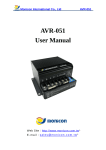
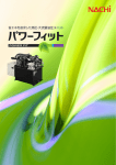
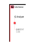
Cutler-Hammer
P49882 Rev 01
Instruction Manual:
E58 Self-Contained Diffuse Reflective 18mm Tubular Sensors
Models covered in this manual:
Mode
Light Sense (N.O.)
Dark Sense (N.C.)
AC/DC Models
E58CAL18A2D2
-E58CBL18A2D2
--
DC-only Models
E58CAL18T110D2 (NPN)
E58CAL18T111D2 (PNP)
E58CBL18T110D2 (NPN)
E58CBL18T111D2 (PNP)
WARNING
THESE PRODUCTS ARE NOT DESIGNED, TESTED, OR
RECOMMENDED FOR USE IN HUMAN SAFETY
APPLICATIONS.
The E58 Diffuse Reflective photoelectric sensors contain both
the light source and detector in an 18mm diameter tubular
housing. The light source is a light emitting diode (LED) which
produces a visible beam of light. The beam is modulated to
reduce the susceptibility of the detector to ambient light - the
detector responds only to the modulated light source.
All of the electronics necessary to produce and detect the
modulated beam are contained in this one housing. An
indicating LED is incorporated in the cable end of the sensor to
indicate operation. This indicator is useful for set-up and
diagnostic purposes.
Diffuse
Reflective
Diffuse Reflective
USE #4 MOUNTING HARDWARE ONLY! LARGER
HARDWARE WILL DAMAGE THE SENSOR AND MAY
CREATE AN ELECTRIC SHOCK HAZARD. TIGHTEN THE
HARDWARE JUST TO THE SENSOR BODY SO NO
DEFLECTION OF THE BODY OCCURS.
DURING INSTALLATION, CORRECT POWER
CONNECTIONS MUST BE MADE FIRST TO ENSURE FAILSAFE SHORT CIRCUIT PROTECTION OF THE OUTPUTS.
REFER TO THE WIRING DIAGRAMS IN THIS MANUAL.
DO NOT USE TOOLS TO APPLY TORQUE DIRECTLY TO
SENSOR BODY. ALIGN SENSOR BY HAND BEFORE
TIGHTENING MOUNTING HARDWARE.
THE GAIN ADJUSTMENT POT IS A 3/4 TURN POT. ANY
RESISTANCE ENCOUNTERED WHILE ADJUSTING THIS
POT INDICATES YOU HAVE REACHED THE ADJUSTMENT
LIMIT STOP. TURNING PAST THIS STOP WILL DAMAGE
THE SENSOR.
MOUNTING
The E58 sensor features a threaded housing and includes jam
nuts and washers. This allows mounting into any 0.75 inch
hole, or any of the mounting brackets shown on page 4 of this
manual. Use caution to avoid cross-threading the jam nuts on
the sensor body. Tighten jam nuts to less than 4 Nm (36 in.lbs. or 3 ft.-lbs.) torque to avoid stripping threads.
USE ONLY A SUITABLE ADJUSTMENT TOOL OR FLAT
BLADE SCREWDRIVER WHEN TURNING THE ADJUSTMENT
POT. SHARP OBJECTS CAN DAMAGE THE POT AND
RESULT IN ELECTRIC SHOCK.
INTRODUCTION
A diffuse reflective sensor operates by shining a beam of light
out through the lens. When an object comes within the
sensor’s view, it reflects part of this beam of light back to the
sensor causing the sensor to detect the object. The maximum
range at which a given object can be detected depends on how
well its surface reflects light—the less light it reflects back, the
shorter the range. The ability of a surface to reflect light
depends primarily upon its material of construction, color and
texture.
Mounting
E58 sensor
using #4
hardware.
Mounting
E58
sensor
using
jam nuts.
A second mounting method is to use #4 hardware in the 0.125
inch diameter mounting holes in the flat sides of the sensor.
This is ideal for mounting the E58 sensor against a wall, piece
of equipment, rail, mounting bracket, etc.
P49882 Rev 01
Page 2
MOUNTING LOCATION AND SET-UP
Select a mounting location with a clear view of the object to be
detected. Avoid direct reflection from a highly reflective
background (or darken the background). Mount the sensor so
that it points at the most suitable part of the target object.
Be sure your power supply is OFF, then connect the sensor to
the control circuit and power lines. Turn the power supply ON
and place a sample object in the beam. Slowly turn the gain
adjustment clockwise (see Warning on page 1 concerning pot
adjustment) until the LED lights (in light-sense mode). Note the
position and remove the sample object. Now continue turning
the sensitivity setting clockwise to find the position where the
LED lights from the background reflection. Reset the sensitivity
midway between the two positions. Tighten all mounting
screws.
NOTE: If background reflections are low, it will be possible to
achieve a maximum gain setting without the LED lighting; in
that case, set the gain midway between the first setting and
maximum (this will prevent a hysteresis latch-up after sensing
an object).
The detector “sees”
light when the target
surface enters the
Detection Zone. Detection
Zone
Target
Object
If the control’s range is greater
than required to detect the
target, background objects may
reflect enough light to
trigger the control.
Working
Range
Target
Object
Darken the background or reduce
the sensor’s operating range by
turning the sensitivity control
counterclockwise until the
background is no longer detected.
Required Range
Limit
Background
Object
WIRING DIAGRAMS
For wiring cable versions, the color codes shown are the actual wire colors emanating from the sensor.
AC/DC Models (AC Connection)
AC/DC Models (DC Connection, see Warning above)
Load
Blue
Black
Brown
AC/DC
Sensor
L1
+V
Blue
Blue
Black
Brown
AC/DC
Sensor
(-)
+V
DC 10 to 30 V
DC 10 to 30 V
Brown
Black
Load
DC Models (PNP Output)
+V
Load
+V
(-)
L1
DC Models (NPN Output)
(-)
+V
L2
DC 15 to 30 V
AC 20 to 250 V
L2
DC
Sensor
(-)
(-)
+V
Brown
Black
Blue
DC
Sensor
Load
(-)
Effective 6/01
P49882 Rev 01
Page 3
SPECIFICATIONS
AC/DC MODELS (AC Operation)
20 to 264 V AC, 50/60 Hz
Power Dissipation
Output Type
Current Switching
Capacity
1.5 W maximum
VMOS (bi-directional)
300 mA maximum
AC/DC MODELS (DC Operation)
15 to 30 V DC
(15 to 24 V DC above 55° C/131° F)
1.5 W maximum
NPN (sink)
300 mA maximum
Voltage Switching
Capacity
Off-State Leakage
Surge Current
On-State Voltage Drop
375 V peak maximum
375 V peak maximum
250 mA typical; 500 mA maximum
2 A maximum
---
250 mA typical; 500 mA maximum
2 A maximum
1.8 V at 10 mA; 3.5 V at 300 mA
Input Voltage
Response Time
Short Circuit Protection
Light/Dark Operation
Temperature Range
Material of Construction
Cable/Connector
Vibration and Shock
Indicator LED
Sunlight Immunity
Enclosure Ratings
Approvals
10 mA maximum
1 A maximum
NPN: 400 mV at 10 mA, 1.5 V at 250 mA;
PNP: 2.4 V at 100 mA
10 mS
1 mS
Sensor will turn off immediately when a short or overload is detected (Indicator LED will flash).
Turn power OFF and back ON to reset.
IMPORTANT: During installation, correct power connections must be made first to ensure fail-safe short circuit
protection of the outputs.
By model
Operating and Storage: -40° to +70° C (-40° to +158° F)
Lens: Polycarbonate; Cable jacket: PVC; Body: Structural polyurethane foam (do not expose to concentrated acids, alcohols,
or ketones)
3-meter cable, 3-wire
Vibration: 30 g over 10 Hz to 2 kHz; Shock: 100 g for 3 mS 1/2 sinewave pulse
Lights steady when output is ON; Flashes when short circuit protection is in latch condition
10,000 foot-candles
NEMA 1, 2, 3, 4, 4X, 6, 12, and 13
Our products conform to NEMA tests as indicated, however, some severe washdown applications can exceed these NEMA test
specifications. If you have questions about a specific application, contact our Applications Department.
UL recognized, CSA approved, CE compliant
OPTICAL PERFORMANCE
RANGE (mm)
2.5
25
254
2540
1000
EXCESS GAIN
All optical specifications are
guaranteed to be the minimum
performance under clean conditions of any product delivered from
stock. Typical performance may be
higher.
All ranges and excess gain graphs are based on a 90% reflectance white
card.
Effective 6/01
Infrared, 880 nm
8 inches (200 mm)
0 to 5 inches
2 inch diameter at 5 inches
APPROXIMATE DIMENSIONS
(Shown in inches except where noted)
0.125 Diameter
Thru Holes (2 places) Use #4
Hardware Only
100
Dirt in the environment will affect
10
optical performance by reducing
the amount of light the control
receives. For best results, sensors
1
should be used at distances where
0.1
1
10
excess gain is higher than 1.5 (1.5
RANGE (inches)
times the amount of sensing power
required to detect an object under
ideal conditions). Higher excess gain will allow the sensor to overcome
higher levels of contamination on the lens.
Source
Maximum Range
Optimum Range
Field of View
DC-ONLY MODELS
10 to 30 V DC
(10 to 24 V DC above 55°C/131° F)
1 W maximum
NPN or PNP
PNP (source): 100 mA maximum;
NPN (sink): 250 mA max.
(120 mA max. above 55° C/131° F)
30 VDC maximum
Gain
Adjustment
0.11
Indicator
LED
100
Cable
(3m)
0.47
0.32
0.65
1.00
2.20
0.25
M18x1.0
Thread(mm)
(fits into a 0.75
inch hole)
P49882 Rev 01
Page 4
MOUNTING BRACKETS
Mounting Bracket
Allows a minimum adjustment range. Sensor mounts with two jam nuts
(included with sensor).
E57KM18
L-Shaped Bracket
Two per package. Allows a minimum adjustment range. Sensor mounts with two
jam nuts (included with sensor). Chromate finish aluminum
6161A-6501
L-Shaped Bracket with
Slot Bulk
Two per package (order quantity will be sent bulk packed). Allows installation of
sensor with jam nuts in place on sensor body.
6161AS7050
Flat Bracket
Allows a minimum adjustment range. Sensor mounts with two jam nuts and
washers (included with sensor). Chromate finish aluminum
6161AS5295
Flush Mount Bracket
Contoured design with no alignment adjustment. Sensor mounts with #4 studs.
304 stainless steel
616AS5296
Flush Mount Bracket
Same as above except with contour. 304 stainless steel
616AS5297
Adjustable Bracket
Locking vertical and horizontal adjustments for independent adjustments in each
axis. Sensors is electrically insolated from mounting surface. Sensor mounts
with two jam nuts and washers (included with sensor). 304 stainless steel
E58KAM18
Ball Swivel Bracket
Allows 360 degree rotation and 10 degree vertical tilt. Made from NorylÒ .
6181AS5200
18mm Ball Swivel Bracket
Allows 360 degree rotation and 10 degree vertical tilt. Suitable for use with any
18mm threaded sensor. Made from 5% glass filled ValoxÒ .
E58KAM18B
.
Still Need Help?
Contact the
Cutler-Hammer Sensor
Application Engineers
1-800-426-9184
Fax: 425-513-5356
Cutler-Hammer
720 80th Street SW
Everett, WA 98203-6299
425/513-5300 Fax: 425/513-5302
www.cutlerhammer.eaton.com
Effective 6/01
Printed in U.S.A.