1
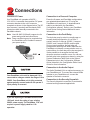
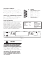
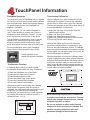
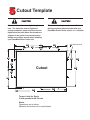
EXPRESS SETUP
PanelMate 1700 Series
PanelMate Power Series
Cutler-Hammer
Installation
Unpacking
Safety Considerations
Carefully remove all equipment from the packing
cartons and inspect all parts for damage in
shipment. Check packing cartons for all items
shown on the packing list. Keep the cartons and
packing materials for future shipment.
This equipment is suitable for Class I, Division 2,
Groups (A,B,C,D) or non-hazardous locations only.
Report any damage to the carrier who delivered the
equipment, then contact your Cutler-Hammer
distributor. If you purchased the equipment from
Cutler-Hammer, call the Order Processing
Department at (614) 882-3282. Note: The Interstate
Commerce Commission has a time limit on
reporting concealed damage.
EXPLOSION HAZARD. SUBSTITUTION OF
COMPONENTS MAY IMPAIR SUITABILITY FOR
CLASS 1, DIVISION 2.
Parts Checklist
Your packing carton contains one parts kit
containing:
! 1 Packet of mounting nuts and washers
! 2 Two-terminal connectors (audio output &
security keyswitch)
! 1 Three-terminal connector (24VDC power)
RISQUE D'EXPLOSION. LA SUBSTITUTION DE
COMPOSANTS PUET RENDRE CE MATERIAL
INACCEPTABLE POUR LES EMPLACEMENTS
DE CLASSE 1, DIVISION 2.
! 1 Four-terminal connector (fault relay)
Mounting
Your PanelMate Power Series unit is designed for
NEMA 4, 4X, and 12 installations when properly
mounted in a correspondingly-rated enclosure.
Proper installation and enclosure sizing is essential
to ensure long life and trouble-free operation. Your
PanelMate unit should always be mounted in a
vertical position. Flat or angled mounting positions
will shorten the unit's life.
Refer to Cutler-Hammer's PanelMate Power Series
Installation Guide for installation recommendations.
The Guide is available on the Cutler-Hammer web
site:
www.cutlerhammer.eaton.com/automation
Panel cutout dimensions and stud torque limits are
shown on the reverse side of this Express Setup
sheet.
Note: Stud nuts must be tightened enough to
obtain a proper seal, but not over-tightened
to the point where the threads are stripped
or the gasket is rendered useless. Always
use a torque wrench when installing your
PanelMate Power Series unit.
EXPLOSION HAZARD. DO NOT REPLACE
COMPONENTS UNLESS POWER HAS BEEN
SWITCHED OFF OR AREA IS KNOWN TO BE
NON-HAZARDOUS.
RESQUE D'EXPLOSION. COUPER LE COURANT
OU S'ASSURER QUE L'EMPLACEMENT ES
DESIGNE NON DANGEREUX AVANT DE
REPLACER LE COMPOSANTS.
Connections
Connect DC Power
Connection to a Personal Computer
Your PanelMate unit operates at 24VDC 15%/+20%. A removable three-position DC power
connector attaches to the unit's connector
receptacle as shown in the diagram below. The DC
input common (-terminal) and the chassis GND
terminal are both internally connected to the
PanelMate chassis.
Executive firmware and PanelMate configurations
are uploaded/downloaded to a PC using the
PanelMate unit's serial port. A download serial
cable is provided with your PanelMate
Configuration software. Refer to your PanelMate
Power Series Getting Started Manual for more
information.
Note: Use #18 AWG (0.82mm2) copper wire for
power and ground lead connections.
Connection to the Fault Relay
Note: Power conditioning may be required when
the PanelMate unit is installed in areas of
poor power quality.
GND
_
+
The fault relay may be wired in normally open or
normally closed configuration. It is a Form C
contact, rated for 2 amps at 120VAC, 2 amps at
230VAC, and 2 amps at 28VDC resistive load.
During normal operation, the fault relay will
energize after entering Run Mode. Whenever the
PanelMate unit detects a communication error or
system failure, the fault relay will be de-energized. It
is also possible to de-energize the fault relay
whenever an alarm condition occurs. You can set
the fault relay to de-energize on alarms by using the
System Parameters Table. Refer to the System
Parameters topic in the Configuration Software
Online Help and in the Configuration Editor User's
Guide for more information.
Connection to the Audio Output
Your PanelMate unit could be damaged if it is
connected to voltages outside the range of 18 to
30VDC. Your PanelMate unit is fully protected
against polarity reversal and will not operate if
input polarity is reversed.
If you are replacing a PanelMate Power Series
1500 unit, check the rating of your existing
24VDC power supply. The PanelMate 1700 unit
requires a power supply rated for 1.5A
operation.
The Audio Feedback Kit is an optional accessory to
your PanelMate unit. To connect the external 8Ohm
speaker to your PanelMate unit, connect the
speaker to the Audio connector.
Connection to the Security Keyswitch
The Security Keyswitch connection is provided for
external security/password applications.
Connection to Serial Ports
Serial Port 1 may be used for a printer, for PLC (or
Host) communications, or for connection to a
personal computer for upload or download. Serial
Port 2 may be used for a printer or, for PLC (or Host)
communications.
1
2
3
4
Selection of Port 1 for a Serial Printer must be done
with the Configuration Software. Refer to the PLC
Name and Port Table topic in the Configuration
Software Online Help and in the PanelMate Power
Series Configuration Editor User's Guide.
6
7
8
9
5
Pin
1
2
3
4
5
6
7
8
9
Description
RS422 Transmit Data (+) (Output)
RS232 Receive Data (Input)
RS232 Transmit Data (Output)
RS422 Receive Data (+) (Input)
Signal Ground
RS422 Transmit Data (-) (Output)
RS232 Request to Send (Output)
RS232 Clear to Send (Input)
RS422 Receive Data (-)
Serial Port Termination
Your PanelMate unit is sent without termination. For
serial port termination switch locations, refer to
Figure A. Recommended termination for RS232,
DH485 and RS422 communication is shown in the
table. For setting the termination on Serial Port 1,
use the termination switch on the left of Serial Port 1.
For setting the termination on Serial Port 2, use the
termination switch to the right of Serial Port 2.
KYSW
W
W
W
120
SERIAL PORT 1
AC
DH 485
120 Ohm AC coupled
RS422/RS485
SERIAL PORT 2
120
4
2&3
W
W
W
120
Refer to your PLC
Communications Driver
Manual for termination
information
AC
N/C
120
220
220
3 4
1 2
NONE
Termination
None (factory Setting)
NONE
/RS232
3 4
1 2
24V
Communication Position
RS 232
1
/RS232
+ -
FAULT RELAY
Figure A
Your PanelMate unit is equipped with isolated
serial ports for improved communications
reliability. If you are replacing a 120VAC Power
Series unit or a Power Series 1500 unit, and are
using an RS422 or RS485 cable for PLC
communications, you will need to install a new
cable equipped with a ground wire. Consult
your PLC Communications driver manual or
contact Cutler-Hammer Support Services for
more information.
AUDIO
Tests & Adjustments
PanelMate Diagnostic Tests
Display System Configuration Information
When power is applied to you PanelMate unit, the
unit will display a listing of internal diagnostic
checks as they are executed. After completing its
internal diagnostic checks, the unit will display the
Offline Mode Menu. This menu displays six
selections described below:
This selection displays your PanelMate unit's
current configuration. Your PanelMate unit is
shipped with a demonstration PanelMate Power
Series configuration. Once you have downloaded a
new configuration, this information will be updated
to reflect the new configuration information.
Enter Run Mode
Enter
Enter
Display
Execute
Serial
Network
System/
Diagnostics
Transfer
Transfer
Config.
Mode
Mode
Information
Enter
Run
Mode
Calibrate
Touchscreen
Execute Diagnostics
This template allows you to perform a series of
tests:
!
Set Date and Time
!
Display test
!
Touchscreen test
!
Tone, relay and battery test
!
Serial port test
For information on performing these tests, refer to
your PanelMate Power Series Getting Started
Manual.
Enter Serial Transfer Mode
Run Mode allows you to display the configuration
downloaded to the PanelMate unit and
communicate to the PLC of your choice. If a new
configuration has not been downloaded, the unit will
display the demonstration configuration. For more
information on Run Mode, refer to your PanelMate
Power Series Getting Started Manual.
Calibrate Touchscreen
Touchscreen units have a calibration routine that
must be performed to determine the boundaries of
the video on your touchscreen. Refer to
Touchscreen Information for instructions on
calibrating the touchscreen.
Display Contrast Adjustment
Units equipped with grayscale or dual-scan color
displays feature software-controlled contrast
adjustment. To adjust the contrast, follow these
steps:
1) Place the unit in Run Mode
2) Select the Get Page control button from the
default control buttons
To download, upload or read system information
over a serial port, your PanelMate unit must be in
Serial Transfer Mode. For more information on
downloading and uploading PanelMate Power
Series configurations, refer to your PanelMate
Power Series Getting Started Manual.
3) Select the More control button
Enter Network Transfer Mode
To save the new setting, press the Save Setting
control button. To revert to the previous contrast
setting, press the Cancel key. The unit will return to
the last saved contrast level after power is cycled to
the unit.
Network transfer mode is used to read system
information over a remote network or remotely place
your PanelMate unit into Run Mode. For more
information, refer to your PanelMate Transfer Utility
User's Manual.
4) Select the Setup Page control button
5) Select the Adjust Contrast control button and use
the Lighter and Darker control buttons to adjust
the display's contrast.
TouchPanel Information
PanelMate Operation
Touchscreen Calibration
The most basic job of a PanelMate unit is to replace
the functions of hard-wired operator station devices
such as pushbuttons, lamps and message displays.
To replace these devices, the PanelMate unit
supplies a "template".
You can calibrate your unit's touchscreen in both
Offline and Run modes. To access the calibration
screen when in Offline mode, select the Calibrate
Touchscreen template on the Offline Mode Menu. To
access the calibration in Run mode:
During operation, you can select a template to
"arm" control buttons or numeric entry. Once a
template has been selected or "armed", you can
press any desired control button to take action.
1) Select the Get Page control button from the
default control buttons
2) Select the More control button
3) Select the Setup Page control button
4) Select the Calibrate Touchscreen control button
5) Press the Execute control button
The touchscreen is designed for finger or gloved
operation only, and does not require the same
actuation force as a mechanical switch. A light
touch will produce the same result as a heavy one.
For more information refer to your PanelMate
Power Series Online Operation User's Guide.
Pressing directly on the
display will activate a template.
Touchscreen Cleaning
A Cleaning Mode utility is provided to make
touchscreen cleaning safe and easy. To access it:
Although the Offline and Run mode calibration
screens are slightly different in appearance, they
both use the same calibration process. To calibrate,
press the eight boxes/crosshairs located around the
screen edges. You may press them in any order, but
all must be pressed to calibrate.
Each box/crosshair will turn green (different shade
of gray on grayscale units) when pressed. After the
first pass, the boxes/crossharis will change color to
indicate the screen is ready for the second pass.
Again, press all eight boxes/crosshairs around the
screen edge. When you have pressed the last, the
unit will return to normal operation.
10:27:53
Press these
1) Place the PanelMate unit is Run Mode.
2) Select the Get Page control button f
3) Select the More control button.
4) Select the Setup Page control button
5) Select the Cleaning Mode template.
6) Press the Execute control button
After pressing the Execute button, the Cleaning
Mode screen will appear. While this screen is
displayed, the touchscreen will not respond to your
tough. After you have finished cleaning the
touchscreen, you must return to normal operation
by pressing the screen's numbered corners in
sequential order: 1,2,3,4.
10:27:53
1
2
TOUCH KEYS 1-2-3-4 IN
SEQUENCE TO UNLOCK
3
4
boxes/crosshairs
Touchscreen Calibration Program
Copyright (c) Cutler-Hammer 1996. All rights reserved.
twice, in order
(1,2,3,4,1,2,3,4)
CANCEL
PRESS AND HOLD EACH BOX ALONG EDGES FOR 1 SEC.
Pass 1 of 2
Never use foreign objects (pens, screwdrivers
or similar) to activate the touchscreen. Foreign
objects may damage the touchscreen, causing
unreliable operation or failure.
Do not use solvents or other harsh cleaning
compounds on the touchscreen. Solvents and
abrasive cleaning compounds will cause
permanent damage to the touchscreen.
Cutout Template
Care should be taken when tightening the
nuts. The fasteners must be tightened
enough to obtain a proper seal, but not over
tightened to the point where the threads are
stripped or the gasket is rendered useless.
Always use a torque wrench when installing
your PanelMate Power Series unit.
This cutout drawing is not 1:1 scale. Refer to
the Express Setup sheet included with your
PanelMate Power Series unit for a 1:1 template.
4.91
(124.7)
4.91
3.26
3.26
(82.8)
(82.8)
(124.7)
3.47
.187 Diameter Hole
(4.75)
3.25
(88.1)
(82.6)
9.38
(238.2)
1.65
(41.9)
Cutout
6.50
(165.1)
1.50
(38.1)
3.47
(88.1)
9.38
(238.2)
Torque Limits for Studs
5 inch-pounds for #6-32 nuts
Notes:
Dimensions are in inches.
Millimeter dimensions are in parentheses.
4.69
(119.1)
Specifications
Temperature
Operating:
0 to 50 degree C (grayscale & TFT color)
0 to 40 degree C (dual-scan color)
Non-Operating: -20 to 60 degree C
Humidity (non-condensing)
Operating:
20% - 80% (grayscale)
20% - 90% (color)
Non-Operating: 20% - 90% (grayscale)
20% - 95% (color)
NEMA Class:
NEMA 4, NEMA 4X, or NEMA 12
Vibration
Operating:
1g at 10-500Hz
Non-Operating 1g at 10-500Hz
Shock
Operating:
30g
Non-Operating: 30g
Pollution:
Pollution Degree 1 - Rated for exposure to
dry or non-conductive pollutants only
Altitude
Operating:
10,000 feet above sea level
Non-Operating: 40,000 feet above sea level
ESD Immunity
Air:
IEC 1000-4-2, Level 4 (+/- 15kV)
Contact:
IEC 1000-4-2, Level 4 (+/- 8kV)
Radiated Immunity: IEC 1000-4-3 (10V/m) 27mHz to
1GHz 80% AM modulation
Conducted Immunity: IEC 1000-4-6 10V from 150kHz to 80mHZ,
80% AM modulation with 1kHz sine wave
Surge Immunity:
IEC 1000 - 4-5 2kV
Radiated/Conductive CISPR 22, Class A Emission
Electrical Fast Transient:IEC 1000-4-4, Level 3 (2kV) on power
lines (1kV) on I/O lines
Line Frequency Magnetic IEC 1000-4-8 Level 3, 30A/m at 50Hz
Field Immunity:
and 60Hz
Voltage:
24VDC -15%/+20% @28W
(with Fieldbus Interface installed)
24VDC -15%/+20% @23W
(without Fieldbus Interface installed)
Current:
1.3A (with Fieldbus Interface installed)
1.1A (without Fieldbus Interface installed)
Peak Inrush Current: 5A
Serial Port Rate:
Selectable; 110 to 38,400 baud
Serial Port 1 Configuration: DB9S connection selectable for
RS232, RS422, or RS485-2
signal levels
Serial Port 2 Configuration: DB9S connection selectable for
RS232, RS422, or RS485-2
signal levels
Weight:
4 Lbs
5 Lbs with Fieldbus interface attached
Support Services
Technical Support
1-800-809-2772 Voice
1-614-882-0417 Fax
Information Fax-Back
614-899-5323
Website
http://www.cutlerhammer.eaton.com/automation
Technical Support E-mail
[email protected]
Cutler-Hammer
173 Heatherdown Drive
Westerville, OH 43081
614-882-3282
P/N 01-00401-03