1
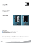
Thank you for choosing the Hogtunes
Big RG Kit. Since positive word of mouth is the
best way to grow our business, we want your
new system to work as well as it was designed
to. If you have any questions or
concerns, we are here to help.
DESIGNED AND ENGINEERED IN CANADA FOR
THE GREAT AMERICAN CRUISER
Email: [email protected]
Tel: 705-719-6361
A video version of this manual is available at
www.hogtunes.com.
If you still need assistance, please
consider a professional installation by
your motorcycle dealer.
INSTALLATION
MANUAL
IMPORTANT: The NCA-40.4 amplifier cannot be used if any external
amplifier is already on the bike. This includes CVO Models with the
factory amplifier under the tour-pak!! This kit will work on CVO models if
the factory amplifier and of its wiring have been removed.
Harley-Davidson, Electra Glide, Road Glide, Street Glide, Ultra Classic, Tri Glide CVO, Screamin Eagle and
Tour-Pak® are Trademarks, and/or Registered Trademarks of Harley-Davidson, Inc., Milwaukee, Wisconsin,
USA, and if Used or Implied are for Reference Only. There is No Affiliation Between Harley-Davidson, Inc., and
Hogtunes Inc.
For Use On Road Glide Ultras or
Road Glides With King Tour Paks
And Rear Speaker Boxes
Radio Sound® is a Registered Trademark of Radio Sound, Inc., Louisville, Kentucky, USA and is Used for Reference Only. There is No Affiliation Between Radio Sound Inc. and Hogtunes Inc.
*Do not install this kit if any external amplifier to the radios built in
power is present. This includes “CVO” models with factory
amplifier under the tour-pak!
MaxxBass® is a Registered Trademark of Waves Audio Ltd., Tel-Aviv Israel. There is No Affiliation Between
Waves Audio Ltd., and Hogtunes Inc.
Harman Kardon® is a Registered Trademark of Harman International Industries Inc., and is Used for Reference
Only. There is No Affiliation Between Harman International Industries Inc. and Hogtunes Inc.
UltrasoundTM is a Trademark of Hogtunes Inc, Ontario, Canada.
Version 1.0
2
GETTING STARTED
Step #1: Remove the seat, and both wires (+ and -) from the battery.
Step #2: Remove the outer fairing/headlamp assembly. Refer to a service manual
if you need help with this. Note: A towel on the front fender can help
prevent scratches or “dings” from dropped tools or fasteners etc.
Expletives will also be kept to a minimum!
Step #3: Unplug the factory wires at each front speaker. Locate and remove the
3 torx head screws, and single “speed nut” that holds each speaker
grill to the bike. The speakers and grills will come off as one unit.
Put these aside.
Step #4: Remove 4 small Phillips screws to separate 5’x7” speakers from new
grills. Locate the bag of screws in the kit. Using these longer Philips
screws, install each Hogtunes grill to the bike, and re-install the stock
“speed nut” on each side. DO NOT use the stock screws for this,
or you will damage your inner fairing. Re-install the 5”x7” speakers to
the grills using the shorter screws just removed, noting that the speakers
must be oriented so the wire connectors are closest to the radio.
Step #5: If installing on a RG Ultra, remove the rear grills and speakers. On any
other model of FLTR without factory wires already in the rear speaker
boxes, go to the next step.
Step #6: Locate the 2ch/4ch switch on the side of the amplifier.
If installing on a RG Ultra:
make sure this switch is in the “4ch”position. In this position, the
amplifiers front and rear channels are controlled independently by
the Road Glide Ultra radios built in fader.
For all other models without factory wires already
in the rear speaker boxes:
Put the switch in the “2ch” position. Locate the 3 position switch on the
side of the amplifier marked “GAIN”, and start with this switch is in the
“+3” position. With the amp in “2ch” mode, the gain switch becomes
active, and is used to adjust the volume of what ever is plugged into the
rear channels. This is ideal for “Non RG Ultras” where there is no fader.
The gain switch allows the rear speakers to be adjusted versus the
fronts, and acts as a quasi “set it and forget it” fader.
3
Step #7: The power harness has an 8 pin white plug with 3 red wires, 3 black
wires, and 1 orange wire. Locate this and plug it into the white socket
on the amplifier marked “power”. The input harness has a smaller black
8 pin plug with smaller gauge wire. Plug this into the black socket on the
amplifier marked “hi level input”. Locate the long “rear speaker” harness
with 8 black wires in it. One end has a white 8 pin connector, the other
end has two 4 pin connectors.
- If mounting in a RG ULTRA: One of the 4 pin connectors on this
long harness will plug into the empty 4 pin plug on the input harness.
It will only go on one way.
- If mounting on any other model of RG: the white plug on
the rear harness that fits the empty white plug on the input harness
does not get plugged in. Let it hang. The other 4 pin plug on the rear
harness will plug into the “rear out” which is a white socket on the
other side of the amp. Locate the 4 pin black plug with black/brown,
and black/blue wires. This will plug into the “front out” on the amp,
which is a 4 pin black socket. Note: There is a blue socket on the amp
labeled “bypass out”. This carries the radios built in power (front
channels) and although not used in this kit, is there for future system
expansion.
BRAKE
SIDE INNER
FAIRING
GLOVE BOX
AMPLIFIER
PLATE
Diagram 1.1 (Amp mounts to brake side of inner fairing “behind” glove box)
The amplifier on its plate is designed to mount on the brake side of the fairing as
show in Diagram 1.1 above. Apply one side of the supplied “hook and loop”
adhesive to the back of the amp plate. The other side will attach direct to the
fairing inner. Line the plate up as shown in Diagram 1.1 and set the amp/amp
plate in place by joining both halves of the hook and loop adhesive together.
When re-assembling the fairing to the bike, the bolts that hold the front turn signal
in place will secure the plate in place, even though the adhesive does most of the
work. Note: Most adhesives work best on clean surfaces and at room temperature!
4
WIRING THE AMPLIFIER
On all input/output and speaker connectors, it’s a good idea to take the female
spade connector and gently squeeze the connector together. Doing so insures a
solid connection when the male spade connector goes in. DO NOT have the male
and female connectors together, and then squeeze, as this will make for a loose
connection!
Step #1: With the amplifier in place, take the yellow/black wires on the input
connector of the amplifier, and plug them into the front factory speaker
wires on the clutch side of the bike. They will only go in one way. Take
the brown/black wires on the “front out” connector and plug them into
the front clutch side speaker. They will only go in one way.
Step #2: Take the green/black wires on the input connector and plug them into
the front factory speaker wires on the brake side of the bike. Take the
blue/black on the front out plug, and plug them into the brake side front
speaker. Again, these will only go on one way.
The amps orange wire is the “remote turn on lead” and tells the amp to turn on
whenever it sees +12v (.5 amp min.). Unplug the center wire (+) from the back
of the cigarette lighter. Plug the orange lead from the amplifier directly onto the
lighter using the female connector. Plug the factory lighter wire to the male “take
off” connector which is part of the amps orange turn on lead.
ROUTING THE MAIN WIRE HARNESS
Step #1: Just in front of the tank, on the brake side of the bike, on the back bone
of the frame is a rectangular opening where factory wires pass from the
inner fairing to the rest of the bike. The power and ground wires, and
rear speaker wires will pass through this opening. Note: install time will
be cut down if another wire is “fished” through from the opening side
into the fairing, taped to the Hogtunes wires, and pulled through.
Step #2: Loosen the tanks “chrome console” and run wires up and over the gas
tank, but under the tanks chrome console. There is a provision on the
front of the tank console for wires to pass. When correctly installed,
the power and ground wires are the right length to run down the brake
side, and connect to the battery. The remaining 8 pin harness is the
right length to run down the clutch side, and be zip-tied to the clutch
side fender strut. Be sure to run the 8 pin harness UNDER the air line for
the clutch side rear shock.
5
Step #3: On the 8 pin rear harWIRE HARNESS
ness “end” you will see
2 pairs of black shorter
END
wires in a sheath, and
2 pairs of black longer wires in a second
sheath. Put the ends of
the shorter wires into the
clutch side rear speaker
box and the longer wires into the brake side. These wires will enter
where the factory wires enter the rear speaker box.
If Installing on a RG Ultra:
Plug the factory rear speaker wires into the male wires of the amp
harness-they will only go on one way. Take a Hogtunes rear speaker
(model 117.2-AA) and plug the female connectors of the amp harness
into the speaker. Again, they will only go one way.
If Installing on any other model of Road Glide:
Take a Hogtunes rear speaker (model 117.2-AA) and plug the female
connectors of the amp harness into the speaker. The male connectors
of the Hogtunes harness will not be used.
Step #1: Once you are confident the wires are correctly attached to the
rear speakers, sit them in place, put the grills back on, and
secure the speakers by reinstalling the 4 screws on each grill.
Join the 8 pin plug that carries wires into the rear speaker
boxes to the 8 pin plug on the long rear speaker harness
sitting on the rear fender strut.
Locate the in line fuse holder, and crimp to the red wire.
Attach the amps black wire to the negative (-) battery terminal,
and the amps red wire to the positive (+) battery terminal.
The factory battery wires are also re-installed at this point.
Note: When attaching the power and ground wires, it is
always a good practice to do the negative first. When the
positive connector touches the battery, some sparking is
normal. This is a function of the capacitors in the amplifier
charging up.
6
Step #2: Turn the stereo on, and at low volume, test to make sure all
4 speakers are working. Note: the system will sound radically
different at speed than it does in your garage. We suggest
leaving the system with the bass and treble in the center
position (flat), and adjusting while at speed. Re-install the
seat making sure the amplifiers “+” and “-” connectors are
positioned in such away so they will not bend or break when
the riders weight is on the seat. This is the best time to take
a few minutes to “clean up” the wiring, and secure using
supplied zip-ties.
Before re-installing outer fairing, turn front wheel
to each extreme side making sure any wiring is not
impeding the steering of the motorcycle. Failure to do
so can result in serious injury or death!
WARRANTY INFORMATION
Hogtunes speakers are warranted for a period of 20 years to the original purchaser.
Hogtunes Amplifiers are warranted for 1 year from original purchase date. Proof of
purchase is required for all warranty claims. The warranty applies to the original retail
customer, and is not transferable. All Warranty claims must be made through the dealer this
product was originally purchased from. Speakers found to be defective during the warranty
period will be repaired or replaced (with a product deemed to be equivalent) at Hogtunes
sole discretion. Amplifiers will be repaired. Hogtunes complete warranty policy is available
at http://www.hogtunes.com/warranty.html
What Is Not Covered:
1) Any expense related to the removal or re-installation of Hogtunes products.
2) Repairs to these products performed by anyone other than Hogtunes.
3) Subsequent damage to any other components.
4) Any product purchased from a non-authorized Hogtunes dealer.
5) Damage to Hogtunes products due to an accident or collision.
6) Hogtunes Amplifiers with broken or removed “warranty void” stickers.
TECHNICAL SPECIFICATIONS
Re-install the fairing and your system is now ready to enjoy!
Hogtunes NCA 40.4 Amplifier
RMS Power at 2 Ohms:
Max Current Draw:
Freq. Response:
Efficiency:
Fuse at Amp:
Amp (only) Weight:
40 watts x 4
< 8 Amps
40hz-18khz
>60%
15 amp
1 KG (2.2 Lbs.)
Hogtunes #572.2-AA Front Speakers
Power Handling:
Frequency Response:
Sensitivity :
Nominal Impedance:
50W RMS-100W Peak
45hz-25Khz
92 dB 1watt/1meter
2.0 Ohms
Hogtunes #117.2-AA Rear Speakers
Adjusting the Bass levels:
The MAXXBASS feature built into this amp has almost as much power as a
386 computer! This feature allows us to “tune” the amps sound for the motorcycle
application. On Radio Sound (1998-2005 model ) radios, between 5-6 “bars”
is all that is needed on the bass level screen. On Harman-Kardon(2006+) radios,
1-3 bars above center is what we have found works best. This is a suggestion only.
Adjust the system for what sounds best to you!
7
Power Handling:
Frequency Response:
Sensitivity :
Nominal Impedance:
50W RMS-100W Peak
55hz-25Khz
91 dB 1watt/1meter
2.0 Ohms
Hogtunes products will play much louder than the
Original Equipment, which can be a distraction to the
rider and/or passenger. Please use caution when adjusting,
or playing your stereo at high volume, especially in traffic.
8