1
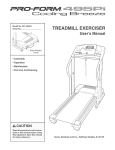
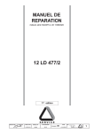
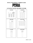
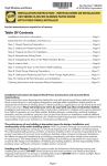
INSTALLATION MANUAL
EZ Lift Bi-Fold Doors
Box 1416 Winkler MB
R6W 4B4
P: 1-204-325-4368
F: 1-204-325-5500
W: ezliftdoors.ca
TABLE OF CONTENTS
1. Thank You
2. Introduction & General Notes
2.1. Intent of Installation Manual
2.2. Door Frame Overview
2.3. Parts List & Consumables
2.4. Safety
2.5. Estimated Installation Times
3. Door Frame Unloading, Handling & Preparation
3.1. Unloading Procedure
3.2. Door Frame Handling
3.3. Lifting Door Frame to Full Height
4. Positioning the Door Frame
5. Attaching the Door Frame (Steel Buildings)
5.1. Attaching Hinges to Header
5.2. Installing Roller Catch
5.3. Installing Lock System Latches
6. Attaching the Door Frame (Wood Buildings)
6.1. Attaching Hinges to Header
6.2. Securing Cable Anchors
6.3. Installing Track Angle
6.4. Installing Lock System Latches
7. Attaching Drive Cables
7.1. Fasten Cables to Door Frame
7.2. Attach Cables to Drive Shaft
8. Installing Trim
8.1. Canvas Seal
8.2. Base Flashing
8.3. Centre Trim & Insulation Stop
8.4. J Trim & Canvas Seal
8.5. Track Angle Cover
9. Installing Insulation & Cladding
9.1. Starting Insulation Panel
9.2. Remaining Insulation Panels
9.3. Installing NSM 800 Cladding
10. Installing Seals
10.1. Retainer Seal
11. Wiring
12. Rotary Limit Switch
13. Photo Eyes (Optional)
14. Remote (Optional)
15. Operating Procedure
16. Maintenance
17. Warranty
18. Conclusion
NUSTEEL Industries
Erection Manual 2014
4
4
6
7
8
10
13
15
17
19
19
20
21
21
22
22
22
22
2
FIGURES
1.
2.
3.
4.
5.
6.
7.
8.
9.
10.
11.
12.
13.
14.
15.
16.
17.
18.
19.
20.
21.
22.
23.
24.
25.
26.
27.
28.
Door Frame Overview
Unloading Procedure
Door Frame Handling
Lifting the Door
Placing the Door
Bottom Gap
Hinge Attachment
Installing Roller Catch
Lock System
Hinge Attachment
Securing Cables
Track Angle
Lock System
Drive Cables
Attaching Cables to Drive Shaft
Canvas Seal
Base Flashing
Centre Trim & Insulation Stop
Canvas Seal
J Trim & Caulking
Track Angle Cover
Starting Insulation
Remaining Insulation
Installing NSM 800 Sheets
Retainer Seal
Limit Switch Location
Adjustment Screws
Circuit Board
4
6
6
7
7
8
8
9
9
10
11
12
12
13
14
15
15
16
16
16
17
17
18
18
19
20
20
21
1. THANK YOU
Thank you for choosing an EZ LIFT Bi-Fold Door. We hope that the following pages will make your door easier to install.
Please let us know if you find anything missing from our manual so we can make the necessary changes. Your input is
crucial to our business and we appreciate your feedback.
2. INTRODUCTION & GENERAL NOTES
2.1 Intent of Installation Manual
EZ LIFT manufactures quality bi-fold doors for commercial and industrial use. Installation can be done by the customer,
an outside contractor, or through EZ LIFT. This manual is a guide for installing bi-fold doors made by EZ LIFT. Customer
satisfaction depends on the skills of a knowledgeable installer given the variety of worksites, equipment, and customizable
options available. It is recommended that the customer, contractor, and/or installer read and become familiar with the EZ
LIFT Bi-Fold Door Installation Manual to run a safe and efficient worksite that produces a long lasting door system.
2.2 Door Frame Overview
Hinges
Bridge
Centre Tubes &
Hinges
Bridge
Drive Shaft
Electric Lock
System Housing
Electrical Box
Motor
EZ Lift Bi-Fold Doors
Figure 1: Door Frame Overview
Bi-Fold Door Installation Manual
4
2.3 Parts List & Consumables
Your EZ Lift Bi-fold Door package should contain the following pieces:
Parts List:
1.
2.
3.
4.
5.
6.
7.
8.
Door Frame
Locking Brackets + Spacers +1/2” Bolts w/ Locking Nuts
Drive Shaft Cable Shroud
12” Canvas Seal
Insulation Panels
Cladding Panels
Retainer Track
Retainer
Trim List
1.
2.
3.
4.
Base Flashing
Centre Trim
Insulation Stop
J-Trim
Additional Hardware and Supplies
1.
2.
3.
4.
5.
6.
7.
8.
9.
10.
11.
12.
13.
14.
15.
16.
Tek Screws (1” and 3”)
⅞” Stitch Screws
Wafer Tek Screws (1” and 3”)
Caulking Tube
½” x 10” Bolts
½” Nuts
½” Large Washers
5
/16” x 1” Self Thread Flange Bolts
3
/16” x 2” Flat Head Torx Self Thread Screws
Cable Clamps
Thimbles
⅜” x 3” Lag Bolts (Wood Buildings)
#12 x 3” Flat Head Lag Screws (Wood Buildings)
3
/16” Brace Cables (Wood Buildings)
Turn Buckles (Wood Buildings)
Anchor Brace Brackets (Wood Buildings)
2.4 Safety
Safety is a high priority for EZ LIFT. We make every effort to ensure our own facility is a safe place to work and encourage
owners / contractors / builders to implement safe work procedures as well. We make every effort to coordinate with
workers when unloading materials on the worksite to ensure proper equipment is used and correct procedures are
followed. EZ LIFT cannot control nor dictate the safety of the worksite or safety procedures implemented by the owner /
contractor / installer. We encourage worksites to follow all municipal, provincial, and federal safety regulations to ensure a
secure and efficient erection process.
2.5 Estimated Installation Times
Installation times for a bi-fold door frame will vary depending on a number of factors (building preparation, access to
equipment, access to supplies, crew experience, etc.) but can be done in three to four hours. At this stage, the door frame
will be hanging and operational. Additional time may be required to finish out optional features including insulation, trims,
cladding, etc.
EZ Lift Bi-Fold Doors
Bi-Fold Door Installation Manual
5
3. DOOR FRAME UNLOADING, HANDLING & PREPARTATION
3.1 Unloading Procedure
Most door frames will be shipped in a partially-collapsed position with the centre hinges up. Move toward the side of the
frame with the drive system. Slowly lift the frame by hooking under the centre tubes as shown. Take extra care when
handling so that the frame does not fully collapse or hit the forklift causing damage.
Figure 2: Unloading Procedure
Lift partially collapsed
door from centre
tubes.
3.2 Door Frame Handling
Slowly and steadily drive the door frame from the trailer toward the building opening. Be sure to prevent the door from
swinging excessively as this may result in damage to the frame. Position the door frame in front of the building opening,
roughly centred side-to-side. Lay out temporary pieces of lumber to rest the frame on to prevent damage.
To lower the frame off the forklift, slowly rest the bottom tube on the lumber. In one motion, slowly lower the forks and
reverse the forklift to lay the door down. The forklift operator may require assistance to make sure the door tips in the right
direction and does not slide off the forks. Use proper safety equipment and procedures.
Lower the forks and
reverse the forklift.
Rest door on lumber.
Figure 3: Door Frame Handling
EZ Lift Bi-Fold Doors
Bi-Fold Door Installation Manual
6
3.3 Lifting Door Frame to Full Height
Secure lift straps/chains to the frame as high as possible near a vertical member. Be sure to plan your lifting position to
avoid any interference with the frame. Slowly lift the frame to its full height. For large doors, larger equipment and multiple
lift points may be required.
Lift door from the
highest point
possible with chains.
Figure 4: Lifting the Door
4. POSITIONING THE DOOR FRAME
Slowly approach the building with the frame, making sure that it is centred in the opening. The door is made 3” wider than
the opening so the door should overlap the building 1-1/2” on each side. Place temporary lumber spacers in line with
vertical members. Position the door frame on the spacers with the top of the frame against the bottom of the header. Rest
the frame on the spacers so that the load is split between the forklift and the spacers. It is a good idea to check for sag in
the bottom tube of door between the vertical bracing. Add shims to the lumber underneath the interior vertical members
until a ¼” bow in the bottom tube is created with the high point of the bow in the middle of the frame.
Figure 5: Placing the Door
EZ Lift Bi-Fold Doors
Position the door
frame in the
building opening.
Bi-Fold Door Installation Manual
7
The door frame should sit approximately 1½” above the concrete slab in order to seal properly at the bottom. This may
vary depending on how level the concrete is when poured. Take extra care to precisely level the door frame; a sloping
frame will not roll smoothly. Check multiple points along the frame with a level and use spacers/shims as required
ensuring a perfect fit.
1 ½” Gap
1/2” Gap
Figure 6: Bottom Gap
5. ATTACHING THE DOOR FRAME (STEEL BUILDINGS)
Instructions for attaching the door frame to a wood building are outlined in Section 6.
5.1 Attaching Hinges to Header (Steel Buildings)
Hinges may be welded directly to a steel header beam or bolted using ½” bolts.
Figure 7: Hinge Attachment (Steel)
EZ Lift Bi-Fold Doors
Hinges can be
welded directly to
steel header.
Bi-Fold Door Installation Manual
8
5.2 Installing Roller Catch
Place roller catch (see Figure 8) so that roller touches both the face of the building beam and the inside surface of roller
catch. The catch should be ¾” from outside edge of door frame as shown. Once the catch is in position, weld or bolt it in
place.
Figure 8: Installing Roller Catch
¾”
1/
2”
Ga locking brackets to the columns on either
With the door fully extended and level, attach the locking bracket spacers and
p systems. When the actuator is extended,
side of the opening. Mount the brackets centred vertically with the electric lock
the lock will engage and seal the door closed. When the actuator is retracted, the lock will disengage and allow the door to
fold open.
5.3 Installing Lock System Latches (Steel Buildings)
Figure 9: Lock System (Steel Building)
Door latched in
locked position.
Door unlatched
in unlocked
position.
EZ Lift Bi-Fold Doors
Bi-Fold Door Installation Manual
9
6. ATTACHING THE DOOR FRAME (WOOD BUILDINGS)
Skip ahead to Section 7 if attaching the door to a steel building.
6.1 Attaching Hinges to Header (Wood Buildings)
Hinges must be bolted using 2 - ½” bolts at each hinge location.
Bolt hinges to
wood header.
Figure 10: Hinge Attachment (Wood)
EZ Lift Bi-Fold Doors
Bi-Fold Door Installation Manual
10
6.2 Securing Cable Anchors (Wood Buildings)
Additional cable bracing is required on wood structures to offer more structural strength when the door is open. Attach
cable brackets to the header to line up with the second hinge from each end of the door, to the centre of the header, near
the top of sidewall posts approximately 30 feet away, and to a rafter straight back and up from the centre of the header.
Be sure to pre-drill holes in lumber. Use ½” bolt with nut and washer. Once brackets are attached, feel cable bracing from
bracket to bracket as shown, using extended turnbuckles at the header. The cables should be snug and free of any
obstructions or catches, including rafters. Tighten turnbuckles so that the cable is taut. Do not over-tighten as this will put
unnecessary stress on the building structure.
*
Cable bracket to
sidewall posts.
Figure 11: Securing Cables
45° +
*
*
~30’
Cable bracket to rafter.
Additional framing may
be required to spread
the load between
multiple rafters.
*
Cable bracket to
header with turnbuckle.
Begin with extended
turnbuckle and tighten
until cable is taut.
*
*
EZ Lift Bi-Fold Doors
Bi-Fold Door Installation Manual
11
6.3 Installing Track Angle (Wood Buildings)
Place track angle so the inside edge is flush with the door frame. The measurement should be 3 ¼” from outside edge of
door frame to the inside of track angle as shown. Using a pry bar, pry up the track angle so that the roller is touching both
the face of the track and the track angle roller catch. Once correct height is achieved, place the first screw to hold in place
as shown.
It is important to make sure the 3 ¼” measurement is kept while installing remaining screws.
3 ¼”
1/2”
Gap
Figure 12: Track Angle
6.4 Installing Lock System Latches (Wood Buildings)
With the door fully extended and level, locking brackets to the columns on either side of the opening additional lumber
may be required to frame the opening. Mount the brackets centred vertically with the electric lock systems. When the
actuator is extended, the lock will engage and seal the door closed. When the actuator is retracted, the lock will disengage
and allow the door to fold open.
Door latched in
locked position.
Figure 13: Lock System (Wood Building)
Door unlatched
in unlocked
position.
EZ Lift Bi-Fold Doors
Bi-Fold Door Installation Manual
12
7. ATTACHING DRIVE CABLES
7.1 Fasten Cables to Door Frame
Insert a sleeve through the clamped cable. Place the sleeve between the welded brackets near the top of the door. Insert
a ½” bolt through the sleeve and the welded brackets, fastening with a lock nut. Repeat at each drive cable location.
Guide the cable(s) down over door bridges and through cable push-offs toward the drive shaft.
Figure 14: Drive Cables
Cable secured in
bracket.
Cable attached
to driveshaft
EZ Lift Bi-Fold Doors
Bi-Fold Door Installation Manual
Cable placed
through push-off.
13
7.2 Attach Cables to Drive Shaft
2
1
Thread the cable
through the welded
tube on the drive shaft.
Thread the cable
though the shroud and
set the shroud aside
until it is needed.
Drive Shaft
4
33
Pull free end of cable
until clip stops loop
from being pulled
through. Tighten clip in
place and trim any
excess cable.
Thread the cable back
through the tube to
create a loop. Place the
clip on the cable but do
not tighten.
4
5
Slide the shroud down
the cable onto the drive
shaft.
Secure the shroud with
a ziptie on each end.
Figure 15: Attaching Cables to Drive Shaft
EZ Lift Bi-Fold Doors
Bi-Fold Door Installation Manual
14
8. INSTALLING TRIM
Exact trim profiles may vary depending on customizable options such as insulation and cladding.
8.1 Canvas Seal
Cut the 12” canvas seal to length. Position the Drip Cap (or J-Trim) (not included with door package) above the door,
leaving approximately 6” of clearance from the top of the door frame to the horizontal portion of the flashing. Tuck the
canvas seal between the drip cap and the exterior side of the building framing. Secure the drip cap and canvas seal to the
outside of the building. The seal will be attached to the door in later steps.
Figure 16: Canvas Seal
6”
Clearance
8.2 Base Flashing
Secure the base flashing to the exterior of the door frame. The horizontal portion should be flush with the bottom of the
lower tube.
Figure 17: Base Flashing
EZ Lift Bi-Fold Doors
Bi-Fold Door Installation Manual
15
8.3 Centre Trim & Insulation Stop
Secure the centre trim to the exterior face of the top tube on the bottom section of the frame.Secure the insulation stop to
the exterior face of the bottom tube on the top section of the frame.
Figure 18: Centre Trim & Insulation Stop
8.4 J-Trim and Canvas Seal
Pull the 12” canvas seal over the exterior vertical face of the door frame and leave it hanging over the door frame.
Figure 19: Canvas Seal
Figure 20: J Trim & Caulking
J-trim should be installed on the exterior face of the
door frame along each side of the top section (vertically)
and each side of the bottom section (vertically). Before securing the
J-trim that attaches to the top tube of the top section (horizontally), a
layer of caulking should be placed on the side of J-trim that butts up against canvas seal. This will stop water from running
behind J-trim. Once the caulking is in place, the J-trim can be attached to the frame with screws to create an effective seal
on top of the door.
EZ Lift Bi-Fold Doors
Bi-Fold Door Installation Manual
16
8.5 Track Angle Cover
Track angle trim is installed on exterior face of track angle and should fit over roller catch as shown. It should be fastened
with screws.
Figure 21: Track Angle Cover
9. INSTALLING INSULATION & CLADDING
9.1 Starting Insulation Panel
With all the trim installed, insulation panels can be put in place. Position the starting panel such that the white aluminum
finish is to the inside of the door and the panel is snug to the trim on three sides. All insulation panels are cut to the correct
length by EZ Lift.
Figure 22: Starting Insulation
EZ Lift Bi-Fold Doors
Bi-Fold Door Installation Manual
17
9.2 Remaining Insulation Panels
The insulation panels work on a tongue-and-groove system. As each remaining panel is put in place, it should connect to
the previously installed panel. Tape each seam with Tuck Tape. Trimming may be required for the last panel.
Seal seams with
Tuck Tape.
Figure 23: Remaining Insulation
9.3 Installing NSM 800 Cladding
Position the starting panel on the exterior side of the insulation, against the previously installed trims and screw in place.
Overlap the remaining panels and cut last panel as required.
NSM 800
Cladding
Figure 24: Installing NSM 800 Sheets
EZ Lift Bi-Fold Doors
Bi-Fold Door Installation Manual
18
10. INSTALLING SEALS
10.1 Retainer Seal
The retainer track and seal are installed at the bottom of the door on the interior side by securing the track to the frame
with tekscrews. Lastly, slide the retainer into the track. When the door is closed, the retainer will compress and create a
seal with the concrete.
Retainer track
6” Seal
Figure 25: Retainer Seal
11. WIRING
EZ Lift Doors come fully wired to the customer so minimal electrical work is required on site. The wires are labelled and
should be hard wired in above the header via a pigtail connection.
EZ Lift Bi-Fold Doors
Bi-Fold Door Installation Manual
19
12. ROTARY LIMIT SWITCH
The rotary limit switch controls how high the door will open
(Open Limit or Up Limit) and when the auto-locks will
engage (Close Limit or Down Limit). It is located on the
driveline either beside the motor or at one end of the
driveline. It contains two adjustment screws labeled “1” and
“2”. It also has a centre screw that needs to be loosened
before adjustments are can be made to the limits.
Rotary Limit Switch
Use caution when setting limits.
Opening the door higher than it was designed to go
may cause damage to the door.
Figure 26: Limit Switch Location
To make adjustments:
1. Take the cover off of the limit switch
2. Loosen the centre screw
3. Screw 1 (Close Limit or Down Limit): Generally only minor adjustments are required from factory settings.
When the door locks, the cables should have some slack.
4. Screw 2 (Open Limit or Up Limit): Open the door and take note of the opening height the door acheives.
Adjust the screw in small increments, re-open the door and observe how the adjustment has affected the
opening height. Repeat this procedure until the proper opening height is achieved.
5. Once the proper limits are set, tighten the centre screw to lock the settings
6. Retun the cover to the limit switch and make sure the rubber seal is properly seating on the housing.
Screw #2
Screw #1
Centre Screw
Figure 27: Adjustment Screws
EZ Lift Bi-Fold Doors
Bi-Fold Door Installation Manual
20
13. PHOTO EYES (OPTIONAL)
Photo eyes are an optional upgrade on an EZ Lift Bi-Fold Door. Sensors should be placed 6” off the ground at each end of
the door. Sensors are hard wired to the door’s electrical box.
Photo eyes have a minimum distance of 9’-0” and cannot be placed next to each other.
Doing so will cause issues on the board.
If the door was ordered with photo eyes, there will be a 4’-0” pigtail at the top of the door that is labeled as follows:
SNS(N/O Contact), 24VAC(2 wires), Common.
Wiring and installing photo eyes:
1. Run a 4 conductor low voltage wire to one side of the door and a 2 conductor wire to the other side
2. Hook the 4 conductor wire into the receiver and the 2 conductor wire into the transmitter.
3. Both the receiver and the transmitter receive 24 VAC from the electrical box. The remaining 2 wires on the 4
conductor wire get wired to the N/O (normally open) contact wire and the common wire on the receiver.
4. Once the eyes are wired and powered up, both the receiver and the transmitter should have green led
indicator light on solid. If the green light is flashing, there is either an obstruction or the eyes are improperly
aligned. Remove obstructions or re-align the eyes to resolve the issue so both units show a solid green light.
5. Turn the white dial on the circuit board (located in the electrical control panel) to B2. This setting allows the
user to push the close button once without needing to hold the button in. The door will close and lock itself.
If everything is hooked up correctly, the SNS LED indicator on the circuit board will light up when an obstruction is placed
between the photo eyes. If this is done while the door is closing, the door will stop and reverse to the open position. The
SNS LED indicator should only go on when an obstruction occurs. If the light is on and there is no obstruction, an error
occurred during installation. In this case, troubleshoot the following items:
-
Make sure the N/O (normally open) contact is used on the receiver
Make sure the photo eyes have power
Make sure the photo eyes are properly aligned
Make sure the phote eyes are at least 9’-0” apart.
14. REMOTE (OPTIONAL)
Wireless remotes are an optional upgrade on an EZ Lift Bi-Fold Door. For safety reasons, this option is only available in
conjuction with photo eyes.
To program the remote:
1. Push the white button on the circuit board. A
white LED indicator light beside the button will
light up.
2. With the indicator on, hold the button down on
the remote until the indicator flashes.
3. The remote is now programed to operate the bifold door.
Figure 28: Circuit Board
EZ Lift Bi-Fold Doors
Bi-Fold Door Installation Manual
21
15. OPERATING PROCEDURE
The operating procedure will vary slightly, depending on if you chose to include the photo eye sensor with your door. If
you included it, the door will open/close with the single press of a button. Without the sensor, the operator will be required
to hold down the button for the opening/closing duration.
16. MAINTENANCE
Performing proper maintenance procedures will help ensure your door operates in peak performance for years. Most of
the time, greasing the bottom driveline annually will be sufficient to keep the mechanisms running smoothly. If squeaking
occurs when opening/closing door, grease components more frequently. Pay attention to the condition of the cables on
your door and make sure they are replaced if fraying occurs.
17. WARRANTY
We warrant that our doors will be free from defects in the material and workmanship for 2 years. This does not apply to
products that have been misused, abused, or normal wear from operation. The warranty does not cover failures or
breakdowns caused by improper installation or incidental damages. Warranty is also voided if setup is altered in any way
without factory pre-approval from EZ LIFT.
We stand behind our products so if there is an issue with your door that you believe should be covered under warranty
please contact us and we will take the necessary actions to correct the problem.
18. CONCLUSION
Thank you again for choosing an EZ LIFT bi-fold door. We strive to make quality products and take pride in our customer
service. If you have any comments, questions or concerns about your door or this manual do not hesitate to contact us.
Your input is crucial to our business and we appreciate your feedback.
EZ Lift Bi-Fold Doors
Bi-Fold Door Installation Manual
22