1
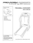
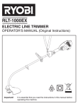
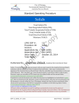
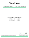
K-Line™ G-Set Irrigation
Installation and user manual
Solid Set Irrigation for pasture
RX PLASTICS LTD
PO Box 360 Ashburton
Phone +64 3 307 9081
Email [email protected]
www.rxplastics.co.nz
K-Line™ G-Set irrigation
G-Set is an irrigation ‘system’, and to
achieve the desired outcome, must be
approached and treated as such, and
not an accumulation of components.
G-Set is a solid set fixed system that minimises “labour” for
the day to day operation of irrigation.
It is suitable for all land areas, and is not restricted by the
shape, terrain, size or topography.
Due to this flexibility, there are numerous configurations
of valves, pressure regulation and sprinkler selection, to
accommodate the various design requirements.
Contents
G-Set installation guide
This is a guide to the best practice of installing
G-Set. Failure to follow these instructions
can lead to instability and poor performance.
These installation instructions apply to all of these options.
Wireless Controller (IPC)
mounting instructions
RX Plastics has developed two “control” options to operate
the system.
Guides to ensure you get the optimum
performance from your IPC.
The first is a wireless radio mesh system of control which
allows the operator to communicate with the units remotely
from any point from which a single unit is visible.
Battery controller (C1013)
With this system we do not require direct line of sight to all of
the units.
The second is an individual, battery operated control.
These units need to be synchronised and programmed
prior to installation and any future adjustment must be done
individually or on a group basis.
2
3–6
A guide to ensure you get the optimum
performance from your K-LineTM G-Set
C-1013 control.
7 – 12
KLGS.RX2000
13 – 15
KLGS.C1013
G-Set unit installation guide
G-Set install tools
A
30mm hole saw – for the tapping
saddle installation
B
½"/13mm long socket 3/8" drive
– for the tapping saddle nuts
C
150mm socket bit 3/8" drive
extension – for the long socket
D
5/16 socket adaptor bit – for
type17 tek screws
E
3/8" drill adaptor
F
Drill
Optional
G
A
F
B
C
D
Ratchet wrench – for tapping
saddle nuts
E
G
The system comprises of a main-line
telescoping through the property,
feeding 63mm MDPE ring-mains. This
ring-main will have the G-Set pods
directly attached to it, using tapping
saddles, at predetermined locations
to suit the paddock layout and terrain
(30m to 40m spacing).
1
The ring-main of 63mm MDPE pipe
needs to be installed below ground
to a depth of greater than 550mm,
particularly at the points where the
G-Set pod is to be located/installed.
This pipe can be trenched or mole
ploughed. A combination of a GPS, a
survey and visual assessment will be
required to ensure correct placement
of the G-Set to achieve the desired
coverage (DU).
1
At the desired location, dig down
and expose sufficient pipe to
allow for the fitting of the 63mm
tapping saddle.
3
G-Set unit installation guide
2
Drill a 30mm hole perpendicular
to the lay of the land. It is
important to ensure this so that
there is no undue force on the
tapping saddle that can result
in it being difficult to achieve a
good long-term seal.
2
It is desirable to dig the hole required for the G-Set no bigger
than necessary to allow the installation and compaction of soil
around the pod. The larger the hole, the harder and more time
consuming it is to get good compaction and secure placement.
3
Fit the tapping saddle, complete
with male coupler and 600mm
riser tube, securely to the pipe.
Fill and firmly compact the soil
in the hole to a height of 350mm
from finished ground level.
4
3
G-Set unit installation guide
4
Lower the G-Set pod over the
riser tube, back fill and firmly
compact ensuring the rim of the
pod is parallel with the lay of
the land. This will result in the
optimum coverage.
5
The unit is now ready for the
valve/sprinkler assembly to be
fitted. This is simply a matter of
sliding this preassembled unit
onto the riser tube, ensuring the
bottom fitting’s sealing o-ring is
in the relaxed cavity down to the
required height (top sprinkler flush
with the top of the pod). Hold the
blue nut and rotate the assembly
until the bottom fitting is tight.
4
5
Attention needs to be given to ensure the 32mm riser tube
is not too long and going to foul the finger filter in the
valve. The riser tube will need to be shortened if the 63mm
pipe is mole ploughed to the minimum depth.
5
G-Set unit installation guide
6
Locate the first half of the cover/
support into the pod and screw
into place with the dish/indent
facing north or best orientation
to capture maximum sunshine
hours.
6
At this point, fit the chosen
control option, following the
installation guide for that control
system.
7
Locate the second half of the
cover/sprinkler support and
screw into place ensuring the
base of the sprinkler is firmly
held around the orange slip ring
on the sprinkler. Three tekscrews are supplied to attach
each cover half.
8
Install the stock guard and the
unit is ready for commissioning
7
8
NOTE: Use a drill with a clutch to avoid the stripping of the
PE on the tek screw hole.
6
Wireless controller (IPC) mounting instructions
Wireless controller
(IPC)install tools
1
A
3mm drill bit – for the IPC plate
mounting holes
B
4mm drill bit – for the zip clip
mount holes
C
10mm drill bit – to drill the aerial
tube holes
D
Drill
E
Phillips head screwdriver – to
screw the IPC down
F
Side cutters – to cut the zip clip
ends
A
E
B
C
KLGS.RX2000
D
F
Place the IPC mounting block
behind the tray on the support
lids. Fix this in place with the two
supplied self tapping screws in
the recessed holes.
1
7
Wireless controller (IPC) mounting instructions
2
Drill 3mm holes into all of the
holes through the bracket into
the polyethylene lid.
KLGS.RX2000
2
10mm
3mm
Make the oblong hole fully
drilled using a 10mm drill for
this process.
3
Sit the IPC on the mounting
bracket with the wires and aerial
fed down into the valve area of
the G-Set.
Screw in the IPC mounting
screws attaching the IPC to the
lid and bracket.
8
3
Wireless controller (IPC) mounting instructions
4
Screw in the IPC mounting
screws attaching the IPC to the
lid and bracket.
5
Drill 2 x 10mm holes into the
G-Set, immediately behind the
IPC for placement of the 10mm
aerial tubing through which the
aerial will be threaded.
KLGS.RX2000
4
5
9
Wireless controller (IPC) mounting instructions
6
Thread the aerial through the
lower hole to the outside and
thread the tubing onto the aerial.
7
Thread the aerial and top of
tubing into top hole.
10
KLGS.RX2000
6
7
Wireless controller (IPC) mounting instructions
KLGS.RX2000
8
Drill 2 x 4mm holes for the zip
clip to affix the aerial to the inner
rim of the G-Set.
8
9
Ensure that the aerial is
captured by the zip clip then
tighten the zip and remove any
excess length of the zip clip.
9
11
Wireless controller (IPC) mounting instructions
10
Connection of the solenoid
wires is simply connecting green
IPC wire to green solenoid wire
and the black IPC to the black
solenoid wire. This is achieved
by the use of the wire nuts
included.
KLGS.RX2000
10
Installing the Connectors
1. Strip wires ½"
2. Align frayed strands or conductors
3. Do not pre-twist. Place stripped wires together with ends
even, lead stranded wire slightly
4. Twist connector onto wires pushing firmly until hand-tight.
DO NOT over torque
5. Swipe excess sealant in and around conductors.
Do not reuse
11
This is how the IPC should be
mounted.
12
11
Battery controller (C1013)
Battery controller (C1013)
install tools
A
Phillips head screwdriver
B
32mm hole saw – for the attachment of
the socket to the lid of the G-Set
C
KLGS.C1013
A
B
C
Drill
Programming of the
controller should be
completed before
mounting.
1
Connect the controller to the coil
on the Baccara valve.
2
Drill a 32mm hole to mount the
25mm valve socket for the solar
panel making sure that it faces
the best solar collection direction
generally this will be North.
1
2
13
Battery controller (C1013)
3
Screw the 25mm backnut onto
the valve socket. The solar panel
can be cemented into the PVC
socket with PVC solvent cement
if necessary.
KLGS.C1013
3
Double check at this point that
the solar panel will be facing the
direction that captures maximum
sunshine hours.
4
The solar cable is then fed down
through the socket to connect on
to the controller. Plug the cable
from the solar panel to the cable
from the controller as shown.
14
4
Battery controller (C1013)
5
KLGS.C1013
Taking the included wire nuts,
you are then able to connect
the solenoid (latch) coil to the
controller. See controller data
sheet for instructions.
5
Installing the Connectors
1. Strip wires ½"
2. Align frayed strands or conductors
3. Do not pre-twist. Place stripped
wires together with ends even,
lead stranded wire slightly
4. Twist connector onto wires
pushing firmly until hand-tight.
DO NOT over torque
5. Swipe excess sealant in and
around conductors.
Do not reuse
6
Connect black latch wire to black
controller wire and the green
latch wire to the red controller
wire. This is achieved by the use
of the wire nuts included.
6
This is how the C1013 controller
should be mounted.
15
Agent:
RX PLASTICS LTD
PO Box 360 Ashburton
Phone +64 3 307 9081
Email [email protected]
www.rxplastics.co.nz
JULY 2014