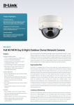
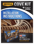
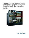
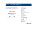
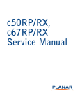
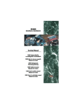
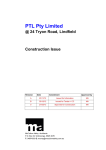
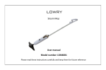
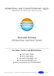
1
CCI Manufacturing Inc.
INSTALLATION MANUAL
WallBAR™ Insulation
WallBAR™ Insulation System
INSTALLATION MANUAL
Updated September 2014
WallBAR™ is a formed-in-place fibrous insulation system for use in exterior walls,
interior and party wall applications, sloped and cathedral ceilings, and rim joist areas.
WallBAR™ may be installed only under a licensing agreement with Can-Cell Industries Inc.
The WallBAR™ Advantages:
♦
♦
♦
EFFECTIVE AND HIGHLY STABLE R-VALUE ♦
RESISTS CONVECTIVE AIR LEAKAGE AND CONDENSATION ♦
♦
WARMER WINTERS
♦
♦
♦
♦
GREATER COMFORT ♦
QUIETER ENVIRONMENT ♦
LOWER ENERGY COSTS FOR LIFETIME ♦
♦
♦
COOLER SUMMERS
HELPS PREVENT WOOD DECAY ♦
RESISTANT TO MICE AND OTHER PESTS ♦
AN “ENVIRONMENTAL CHOICE” PRODUCT ♦
Contains 100% recycled paper
M – an official mark of Environment Canada
Manufactured and Licensed By
CCI Manufacturing Inc.
Office: 16355-130 Avenue, Edmonton, Alberta T5V 1K5
Phone (780) 453-3610 Fax (780) 447-2443
1-888-269-6977
www.weathershield.ca
WallBAR™ Installation Manual
Updated September 2014
Page 1 of 17
CCI Manufacturing Inc.
INSTALLATION MANUAL
WallBAR™ Insulation
Serving Western Canada
WallBAR™ Installation Manual
TABLE OF CONTENTS
Content Description
Section / Page
Cover Page
--
1
Table of Contents
--
2
Introduction
1.0
3
Factors Affecting Heat Loss
2.0
4
Air Infiltration / Leakage
2.1
4
Convection
2.2
5
Conduction
2.3
6
Radiation
2.4
6
3.0
6
General
3.1
6
Installer Qualification
3.2
6
Installation and Materials
3.3
7
Equipment Calibration
3.4
8
Job Site Preparations
3.5
10
Installation Procedures
3.6
13
Finishing Procedures
3.7
14
Inspection
3.8
15
Limitations
3.9
15
Record Keeping
3.10
15
Job Site Placard
3.11
16
Master Job Record
3.12
16
Air Exchange
4.0
16
Warranty
5.0
16
Description of the WallBAR™ Insulation System
WallBAR™ Installation Manual
Updated September 2014
Page 2 of 17
CCI Manufacturing Inc.
1.0
INSTALLATION MANUAL
WallBAR™ Insulation
INTRODUCTION
The WallBAR™ Insulation System has become a popular choice among discerning builders and
consumers. This system uses the WallBAR™ Insulation manufactured in accordance with ULC product
(CFI) standard, CAN/ULC-S703 (for Type 1 and/or Type 2 applications). The quality of this product is
further ensured by a manufacturing system based on the requirements of the ISO 9001 quality assurance
model. The WallBAR™ product and application system has also been evaluated by the Canadian
Construction Materials Centre (re: CCMC Evaluation Report No. 12344-R and Masterformats 07215.5,
07216.2 and 07215.1). This product also carries the “Ecologo” of Canada’s Environmental Choice
Program, classifying it as an “environmentally friendly” product.
Installation of the WallBAR™ Insulation System usually involves one of two cavity-injection methods:
1) stapling a permeable retaining membrane (i.e. WallNET fabric netting) to the face of wall studs or the
underside of ceiling joists, and then injecting WallBAR™ (dry) into the cavity formed; or
2) injecting dry fibre through the polyethylene vapour barrier to which vertical splines, horizontal
strapping (or a combination of both) is applied prior to insulating.
In addition, perimeter rim joists can be insulated using a variation of these methods – this practice will
eliminate the significant heat loss that can occur in these areas.
Moisture may be added, as an option, to activate the internal adhesive (added to the material during the
manufacturing process) so that a snug-fitting, cohesive matte of insulation is formed more quickly.
Alternate methods of application (not included in CCMC 12344-R) involve direct wet-spraying WallBAR™
into open wall cavities:
-
-
in exterior walls, cavities are filled – the excess of sprayed material is screeded off mechanically
(even with stud faces) providing a “blown-in-blanket” appearance and an effective custom-fit to the
cavity.
for acoustical control in interior (party wall) applications, only a nominal sprayed thickness of 2”–2½”
(5-6 cm) is required before the wall is closed (drywalled).
In any application, WallBAR™ is to be applied at a final dry density of 42-47 kg/m³ (2.6 – 3.0 pcf) – this is
within ±5% of the design coverage value of 44.5 kg/m³ (2.78 pcf). This minimum application density is
necessary to ensure R-value and air leakage protection are supplied.
2.
WallBAR™ may be expected to provide an RSI value of 0.0262 m °C/W per millimetre thickness (R-3.78
per inch) in its nominally dry state. If moisture is added on application, a temporary shortfall in thermal
resistance will occur for the brief period immediately following installation until the material dries (when it
regains its full R-value). Drying time is dependent on weather conditions and the moisture content of the
wood framing, but would not be a significant factor under the range of conditions normally experienced in
the building industry.
WallBAR™ can also be used as a “stabilized” insulation for attics. When applied with moisture (misted
water) in horizontal/blown applications at a final dry density of 28-29 kg/m³ (about 1.8 pcf), maximum
resistance to settlement (normally associated with loose-fill attic insulations) is realized. Virtually no
settlement will occur for the lifetime of the building – so the same (as-installed) WallBAR™ R-value is
retained as well.
Air leakage or air movement through and around an insulating material such as glass fibre batts can
reduce the effective R-value by up to 50%. In addition to convective heat loss, migrating air carries
WallBAR™ Installation Manual
Updated September 2014
Page 3 of 17
CCI Manufacturing Inc.
INSTALLATION MANUAL
WallBAR™ Insulation
moisture vapour outward through cracks and holes in the building structure. When this warm moist air
reaches cool surfaces, condensation occurs, the degree of which may cause further problems. However,
WallBAR™’s shorter fibres, higher density, and seamless blanket cover provide high resistance to air
leakage. WallBAR™ thus prevents condensation problems while maintaining a constant R-value. The
result is a cost effective, environmentally friendly system, with performance far superior to that obtained
by conventional insulation systems.
WallBAR™ is best installed using an approved insulation blowing machine, hose size and length, which
would deliver the fibre at a specified rate and consistency. Such equipment can be modified for specific
“moisture-added” applications.
2.0
FACTORS AFFECTING HEAT LOSS
Although the public is generally aware of the importance of R-value when judging insulation, many
consumers do not fully appreciate that R-value and thickness alone are not an accurate indication of how
well a particular insulation will perform under actual building conditions. Two types of insulation products
having equivalent R-value under lab test conditions may perform quite differently under actual field
(building) conditions.
In order to achieve the rated (expected) R-value, the insulated area must be free of gaps and voids
(around and within the insulation product), and protected from air leakage and internal convective air
currents (around and within the insulation product).
An overall assessment of insulation performance must consider the four basic factors involved in heat
loss – Air Leakage & Infiltration, Convection, Conduction and Radiation.
2.1
AIR LEAKAGE & INFILTRATION
This factor refers to air movement into and out of a building exposed to natural physical forces
(such as wind). Air enters the building through small openings (gaps and voids) in the building
envelope. Incoming cold air displaces an equal volume of exiting warmer air. The incoming cold
air also produces uncomfortable drafts and drops in interior building temperature while the exiting
warm (and moist) air generates condensation moisture as it cools to dew point on its way out of a
wall or ceiling. The overall result is discomfort, energy loss, and moisture damage.
The only way to reduce air infiltration is to build a “tighter” structure.
Cracks and spaces around window and door frames should be sealed. Voids under base plates,
between double studs, and any place where pipes or wires penetrate an upper partition plate
should be caulked. The addition of a moisture-permeable house wrap, and an interior
polyethylene air/vapour barrier will help further in reducing infiltration.
Lastly – but perhaps most important – one should choose an insulation that can provide a seal,
such as WallBAR™, that completely fills every wall cavity, leaving no gaps or voids for air
movement to become a problem.
Such insulation should also be of sufficient material density to effectively resist interstitial
migration of air and moisture within itself – again, a product such as WallBAR™.
Not surprisingly, common glass fibre batts are relatively poor performers with respect to air
leakage. The product is not dense enough to resist air infiltration and, being of pre-cut
dimensions, does not often accurately fit or fill the space into which it is placed. Anyone who has
ever attempted to install batts around obstructions such as electrical boxes, wiring, plumbing
pipes, vent stacks, etc. knows that it is essentially impossible to avoid leaving voids or gaps.
WallBAR™ Installation Manual
Updated September 2014
Page 4 of 17
CCI Manufacturing Inc.
2.2
INSTALLATION MANUAL
WallBAR™ Insulation
CONVECTION
This factor refers to the circulation of air within a space. Heated air rises and, when cooled, falls.
In a wall cavity, the natural forces of gravity, along with warmer inner surfaces and colder outer
surfaces, generate forces that can cause a continuous circulation of air within the cavity, if the
space is not completely filled with a leak-resistant insulation (such as WallBAR™).
Convection patterns within exterior wall cavities and living spaces tend to develop as follows:
1. Cold sheathing cools the air in the wall causing it to move down the exterior side of
the cavity (re: air drops when cooled).
2. The air next to the interior side (warm drywall) rises up inside the cavity (re: air rises
when heated).
3. The greater the difference between the interior and exterior temperature, the faster
the cycle in the convection process.
4. The faster the cycle in the convection process within the wall cavity, the colder the
interior drywall becomes.
5. The colder the drywall, the faster the cycle becomes in the convection process within
the room.
6. The faster the convection loops move within the rooms of the house, the faster the
overall house temperature drops.
7. The faster the house temperature drops, the more energy the heating system uses to
maintain the set temperature.
8. The more energy used for the same heating period, the higher the heating bills will
be for that time.
If the same wall was insulated with WallBAR™, the result would be extremely slow (or entirely
halted) air movement within the cavity. Because convection within the wall would be severely
restricted, the drywall on the interior/warm side would not cool as quickly. And because of the
warmer drywall, there would be a much slower convection current within the house, allowing for
greater comfort (faster convection currents make a room feel drafty).
It should also be noted that the energy efficiency of the windows contribute to the convection
process – colder interior window glass speeds up the convection currents within the house.
Similarly, the thermal effectiveness of attic insulation can be seriously degraded is convective
loops develop within the insulation mass. Because of subsiding cold air, low-density attic
insulation (such as blown glass fibre) will lose 50% or more of its R-value as winter temperatures
drop to –30°C (just when maximum protection is needed). Use of higher density insulations (such
as Weathershield™ or WallBAR™) solves this problem as they resist air movement within.
2.3
CONDUCTION
This factor refers to the transmission of heat energy through a substance by molecular interaction
or contact. Here it is important that the insulation chosen resists heat diffusion through itself.
Mineral/glass fibres are solid materials – the insulation value of such products comes from the
trapped air between fibres – and it is critical that this trapped air remain trapped or “dead” (that is,
that external air movement does not displace it). But as previously mentioned, these products
have low resistance to air infiltration and can therefore allow convective heat loss. The solid
construction of their fibres allows conduction (conductive heat loss) to further contribute to their
unstable R-values. After all, everyone knows that glass conducts heat.
Products such as Weathershield™ or WallBAR™ are comprised of natural cellulose fibres – their
additional insulation value comes from the additional trapped air maintained between and inside
WallBAR™ Installation Manual
Updated September 2014
Page 5 of 17
CCI Manufacturing Inc.
INSTALLATION MANUAL
WallBAR™ Insulation
their hollow fibres. This results in less heat loss by conduction. Their higher density and
resistance to air movement provides for a more stable R-value (due to additional dead air that
remains dead). Cellulose is a relatively poor conductor of heat – but this is what is needed in a
good insulation product.
The exterior side of these products may be hot or cold, as the case may be in summer or winter,
but the interior side remains essentially the same.
2.4
RADIATION
Heat transfer by radiation occurs when energy is transmitted through space.
example of this is the energy transmitted to Earth from the Sun.
The primary
Though not a major factor in heat transfer through insulated spaces, radiant heat tends to raise
roof and attic temperatures, from 40°C to as much as 70 °C (about 110-160°F) range during the
summer months.
Under such conditions, glass fibre insulations lose substantially more of their thermal resistance
than do products like WallBAR™. Glass tends to radiate the heat it has absorbed, challenging its
ability to insulate effectively. Cellulose fibres are not subject to such radiative heat loss.
Consequently, WallBAR™ will not only help keep a home warmer during cold weather, but will
also keep it cooler during hot weather.
3.0
DESCRIPTION OF THE WallBAR™ INSULATION SYSTEM
3.1
GENERAL
The information in this section covers the following:
3.2
-
Installer Qualification
-
Installation Equipment & Materials
-
Preparatory Procedures
-
Installation Procedures & Techniques
-
Limitation of the WallBAR™ System
-
Job Documentation
INSTALLER QUALIFICATION
The persons qualified to perform WallBAR™ Insulation System installations have been certified
as competent in such work by Can-Cell Industries Inc. or a licensee holding a current WallBAR™
License Agreement.
The Licensee shall be responsible for ensuring installation work performed respective to the
License Agreement is done with quality/workmanship in high regard, and in accordance with
recommendations provided by Can-Cell Industries Inc.
WallBAR™ Installation Manual
Updated September 2014
Page 6 of 17
CCI Manufacturing Inc.
INSTALLATION MANUAL
WallBAR™ Insulation
WallBAR™ installers carry an identification card certifying their training. This ID card bears the
following information:
-
company name/address/phone of the WallBAR™ installer (Licensee)
name and signature of the representative performing installations
company name of the certification source (i.e. Can-Cell or other Licensee)
company logo of Can-Cell Industries Inc. and WallBAR™ product logo
WallBAR™ Insulation System
INSTALLER’S
IDENTIFICATION CARD
Company (Licensee):
(address)
(phone / fax)
___________________________
___________________________
___________________________
Representative:
___________________________
(applicator)
Signature:
Certification Source / Date:
3.3
____________________
_______________________
INSTALLATION EQUIPMENT & MATERIALS
WallBAR™ System installation equipment shall include the follows:
-
A pneumatic insulating machine (suitable for typical CFI application) of a type
approved by Can-Cell Industries Inc.
-
2½” or 3” (63 or 75mm) ID corrugated delivery hose (size depends on machine) –
minimum length: 150’ (45 m) – equipped with a 30°-bend wall nozzle (available
through or otherwise approved by Can-Cell Industries Inc.).
-
non-permeable retaining membrane shall be 6-mil CGSB-Approved polyethylene
vapour barrier.
NOTE: Depending on the application, vertical splines (1”-wide paperboard
strips), horizontal strapping (“1x2”s or “1x3”s) or a combination of both would be
applied to secure this membrane prior to installing the insulation.
-
permeable retaining membrane (woven fabric netting) shall be as approved by CanCell Industries Inc., and shall be referred to as “WallNET”.
NOTE: Depending on the application, horizontal strapping may be used to
increase the available insulating thickness of the wall cavity.
-
pneumatic stapler (and air compressor) and standard ½” (12mm) staples – to secure
the retaining membrane in place. Alternatively, a hammer tacker may be used in
certain situations.
-
the insulation product shall only be WallBAR™ Insulation (i.e. Can-Cell product –
available only through Can-Cell Industries Inc. or a WallBAR™ Licensee)
WallBAR™ Installation Manual
Updated September 2014
Page 7 of 17
CCI Manufacturing Inc.
INSTALLATION MANUAL
WallBAR™ Insulation
For “moisture-added” option only:
By Injection: - although dry-injection is most popular, a modification package can be
obtained from Can-Cell that would inject misted water into the exit
stream of the machine blower. Equipment would include a water pump,
3/8” line, spray nozzle/jets, shut-off valve and pressure regulator.
By Wet-Spray: - since this involves a direct spray method, equipment would include:
-
diaphragm (water) pump, 3/8” pressure line (of delivery hose length)
and shut-off valve
WallBAR™ Spray Injection Nozzle:
2-jet or 4-jet version (using 4001/4002 tips)
powered “Stud Scrubber” (available through Can-Cell Industries Inc.)
NOTE: For “stabilized” attic installations, municipal water pressure tends to be suitable.
For sloped and cathedral ceiling applications:
-
-
3.4
cardboard (175B or C corrugated/unwaxed) vents or polystyrene foam vents may be
used to provide the required continuous air space above the insulated area.
Alternatively, the air space can be created with WallNET (see installation
procedures).
Can-Cell suggests that, due to its density and corresponding resistance to
air/moisture infiltration, often such sloped cavities can be filled full with WallBAR™.
Although not NBC procedure, no difficulties with this practice have ever been
documented.
EQUIPMENT CALIBRATION
The installer must ensure that the application equipment (insulating machine, water pump and
spray tips, etc.) is maintained in a clean and serviceable state in order to maintain reliable
calibration values.
The main and most important step in equipment calibration is to accurately determine the
optimum dry-fibre delivery rate of the insulating machine.
Each calibration must be carried out under the same conditions as the intended
application – i.e. if it is wall cavities that will be filled, then the determination must be made by
filling typically-prepared wall cavities (complete with the type of retaining membrane that will be
used) using the same length of hose that will be used for the installation work (re: a minimum of
150’ – 3” ID). It is important to achieve the proper installation density (range) as well in
order to validate the calibration.
This is most practically done at the beginning of the actual installation job – this would also serve
as a form of quality control as the application settings can be verified and compared with similar
installation data (re: log records). Such calibrations (and log records thereof) would also function
to provide data for estimating purposes and to monitor the service condition of the insulating
machine.
Because of the variability of the actual installation conditions and requirements from job to job, no
standard optimum rates can be offered. Each installation job is unique and will have its own
specific application rate. For example: 2x6 wall cavity installations will differ from that of 2x4
walls; an 8’ wall will be different that one that is 12’ or more; and vertical wall fills will differ from
WallBAR™ Installation Manual
Updated September 2014
Page 8 of 17
CCI Manufacturing Inc.
INSTALLATION MANUAL
WallBAR™ Insulation
sloped ceiling applications. In addition, the rate for retained-cavity installations will differ from
open-cavity wet-spray applications (which would employ a dry-fibre rate similar to an
open/horizontal (blown attic) rate).
It must also be noted that all rates are quite dependent on the insulating machine being used.
The delivery capacity and optimum delivery volume will vary from machine to machine.
In any case, the actual dry-fibre delivery rate of the machine to be used must be determined – it is
recommended that in order to achieve an accurate rate, determinations should be based on at
least 8-10 bags of product blown. Calculating the total volume insulated for the number of bags
blown will provide an average installed density estimate – adjust as necessary. The results,
settings, conditions, date and any other relevant details should be recorded in the Installations
Log (see Section 3.10 – Record Keeping).
Once the dry-fibre delivery rate has been determined, calculations can then be made for moisture
additions (if required).
For misted injection:
-
in order to properly wet fibres so that the internal adhesive is adequately activated, a
maximum add-on level of 15% moisture (totalling 20-25% by weight of the product)
is recommended.
- This means that for every 10 bags of WallBAR™ installed, about 21 kg or 21
litres (46 lb. or 4.6 gallons) of water should have been applied.
-
In order to co-ordinate the proper amount of water delivery with that of the dry fibre
(rate previously determined), the water spray delivery rate is to be 10% (one tenth) of
that rate.
- Example: if the dry fibre delivery rate is 40 bags/hour (560 kg, 1240 lb. per hour),
then water delivery should be 84 kg/hour or 84 litres/hour (185 lb./hour or 18.5
gallons/hour).
Delivery flow rate is determined by spraying water into a calibrated container (for at
least 3-5 minutes) and adjusting delivery pressure (and/or type of spray tip) until the
desired rate is achieved. Repeat to confirm the rate.
-
The details of such results shall be documented (re: installations log).
For wet-spray method:
-
Similar to above except that the add-on level is 20% maximum. This is because
there is likely a higher dry-fibre delivery rate here – with no retaining membrane –
and in order to wet the fibres enough so that they “stick” in the cavity.
- This means that for every 10 bags of WallBAR™ installed, up to 28 kg or 28 litres
(62 lb. or 6.2 gallons) of water should have been applied, etc.
- Similarly, if the dry fibre rate is 40 bags/hour as above, then water delivery
should be no more than 112 kg/hour or 112 litres/hour (maximum 247 lb./hour or
24.7 gallons/hour).
Calibration is determined (and documented) in the same manner as above. Values
would be valid for either filled-cavity or party wall applications.
Sloped and Cathedral Ceilings:
-
The installation for sloped and cathedral ceilings is the same as for walls, except:
there is a continuous ventilated air space required; these applications are ALWAYS
blown with dry product; and cavities longer than 3 m (10 ft.) must be blown in stages
(see installation procedures).
WallBAR™ Installation Manual
Updated September 2014
Page 9 of 17
CCI Manufacturing Inc.
3.5
INSTALLATION MANUAL
WallBAR™ Insulation
JOB SITE PREPARATIONS
The installer should first take steps to ensure that wall and floor areas of the application site are
cleared of construction debris prior to setting up for any installation.
The effective thickness of the wall insulation may be increased by applying horizontal strapping
(1x2’s or 1x3’s nailed at each stud). Use of strapping increases the effective thickness of the
WallBAR™ installed by an average of 0.6” (15mm). This provides an extra R-2.27 (RSI 0.40) to
the application.
In this case it is recommended that the retaining membrane (poly vapour barrier) be stapled along
the top plate only, then pulled down snug and stapled along the bottom plate – no staples along
the stud faces – and then apply the strapping. This will allow the insulation to bulge to the added
thickness of the strapping as well as fill across the stud faces between each cavity.
The estimated amount of WallBAR™ required should have been predetermined from site
measurements and calculations using the coverage chart below:
WallBAR™ Coverage Chart – Vertical/Sloped Wall Cavities
(Membrane-Injected or Spray-Applied)
Imperial System
Metric System
Minimum
ADJUSTED
MASS
(lb./ft²)
COVERAGE*
Per Bag (ft²)
ACTUAL
Thickness
“RSI”
Value
13.2
0.81
52.9
89 mm
15.5
0.95
45.1
104 mm
ACTUAL
Thickness
“R”
Value
3.5”
4.1”
(STRAPPED)
Minimum
ADJUSTED
MASS
(kg/m²)
COVERAGE*
Per Bag (m²)
2.33
3.96
4.91
2.72
4.63
4.20
(STRAPPED)
5.5”
20.8
1.27
33.6
140 mm
3.67
6.23
3.12
6.1”
23.1
1.41
30.1
155 mm
4.06
6.90
2.82
(STRAPPED)
(STRAPPED)
7.3”
27.6
1.69
25.3
185 mm
4.85
8.24
2.36
9.2”
34.8
2.30
18.6
241 mm
6.13
11.25
1.24
Thermal (R/RSI) values based on test results of R-3.78 per inch (RSI 0.0262 per mm) for Can-Cell’s Edmonton Production Facility.
* Wall cavity coverage values above are based on an installed density of 2.78 lb/ft³ (44.54 kg/m³), a package weight of 14.0
kg (30.86 lb), and a volume allowance of 28% -- 13% for window and door openings and 15% for framing. Actual volume
allowances may vary.
Coverage will be reduced accordingly for walls having higher proportions of insulated space
(or an installation density greater than 2.78 lb/ft³).
Again it should be noted that the above chart was prepared as a guideline for estimating
purposes only. Actual coverage will be dependent upon machine settings, operator
technique, and specifics of the wall configuration.
WallBAR™ Installation Manual
Updated September 2014
Page 10 of 17
CCI Manufacturing Inc.
INSTALLATION MANUAL
WallBAR™ Insulation
Wall Cavities: Through Retaining Membrane
WallBAR™ is injected behind a membrane of either an approved netting (i.e. WallNET) or 6-mil
polyethylene vapour barrier.
Once the type of retaining membrane to be used (and whether strapping will be applied) has
been established, the appropriate procedures apply:
Poly Vapour Barrier
This membrane is secured by stapling through vertical (paperboard)
splines along each stud face, with staples spaced no more than 1-2” (35cm) apart. Splines may be omitted when strapping is used (spaced 24”
(61cm) O.C. and secured with two 2½” (6cm) nails at each stud face).
Netting (WallNET)
This membrane is secured with staples at each stud face – staples
should be spaces no more than 1” (2-3cm) apart.
It is important to ensure that the membrane installed is properly aligned with the building
frame so that it is tight and wrinkle-free.
WallBAR™ injected
through netting (WallNET)
1.
2.
3.
4.
WallNET (netting)
Staples
Injection hose
WallBAR™
WallBAR™ injected
through vapour barrier
1.
2.
3.
4.
5.
6.
Splines (if applicable)
Strapping (if applicable)
Staples
Injection hose
WallBAR™
6-mil poly vapour barrier
WallBAR™ Installation Manual
Updated September 2014
Page 11 of 17
CCI Manufacturing Inc.
INSTALLATION MANUAL
WallBAR™ Insulation
Wall Cavities: Open / Direct Spray
The use of strapping in wet-spray applications is not recommended as a practical or economical
practice (as two separate applications would be necessary to gain only ¾” (2cm) thickness).
Sloped & Cathedral Ceilings:
This applies to any degree of slope (from 0° to 90°) that may be found in a ceiling.
Prior to applying insulation, a continuous ventilated air space of 2½” (63mm) – along the length of
the roof rafters or trusses – must be provided throughout each cavity to be insulated in order to
comply with subsection 9.19.1 of the National Building Code of Canada.
Cardboard vents can be secured along the length of the rafters (or to top cord/webs of trusses)
using staples spaced 3-4” (7-10cm) apart.
Foam vents can be secured (stapled) directly to the roof sheathing – a ½” (12mm) should
separate each foam vent to allow for expansion/contraction.
An alternative method of providing the required air space is to nail spacers (wood strips, either
1x2’s, 1x3’s, or 1x4’s) along the inside/top of the rafter/truss to establish the necessary air space;
then staple WallNET (netting) to the bottom edge (face) of the spacer. Extra emphasis must be
made on the importance of achieving a very taut and uniform surface. To ensure the correct
air space remains after insulating, it is recommended that a 1x4 or 2x4 be used as spacer so that
the expected ½”-1” bulge after WallBAR™ and ceiling gypsum board is added is offset.
NOTE: The area over the top plate of the exterior wall must be blocked in order to prevent
insulation from spilling into the soffit area. If a baffle is not already in place, the installer should
measure for and create one using either cardboard, netting, or scrap wood cut to the appropriate
size and secured in place. Be sure not to block off the air space created.
WallBAR™ in sloped or cathedral ceilings (Typical Assembly – 24” (600mm) O.C. construction)
NOTE: Due to its density and corresponding resistance to air/moisture infiltration, WallBAR™ provides effective air
barrier qualities. Over the years, many sloped and cathedral ceiling cavities have been fully insulated (i.e. completely
filled – no air space). To date, Can-Cell does not anticipate and is not aware of any problems whatsoever that have
occurred as a result of this practice.
WallBAR™ Installation Manual
Updated September 2014
Page 12 of 17
CCI Manufacturing Inc.
3.6
INSTALLATION MANUAL
WallBAR™ Insulation
INSTALLATION PROCEDURES
Wall Cavities: Through Retaining Membrane
-
at a point approximately 12” (30cm) below the top plate and the centre of the cavity, cut an
entry slit in the membrane 3” (7.5 cm) wide and insert the wall nozzle (2-2½” ID aluminum
tube - 24” long) into the cavity.
-
activate the flow of fibre (operate remote control switch)
-
fill the cavity (directing flow downward) from bottom to top (turning nozzle upward once
material has reached the entry point) – once full, stop the flow of fibre.
-
cut another entry slit at midpoint and insert nozzle.
-
add insulation to complete the cavity fill as necessary to achieve a relatively uniform
distribution in density from top to bottom (i.e. within range of 42-47 kg/m³, 2.6-3.0 pcf)
NOTE: Sufficient density will be indicated by a ¼ - ½” outward bulge of the membrane.
Similarly, uniformity of the bulge will provide an accurate indication of the density
distribution throughout the cavity.
-
ensure that the density of the material blown across the underside of the top plate is
somewhat higher to prevent any possibility of a settlement gap forming. This is especially
important when filling 24” (60cm) O.C. wall systems.
-
use as many entry points as necessary to ensure complete fills are made around obstructions
such as electrical boxes.
-
to ensure all cavities have been properly filled (i.e. that resistance to settling is provided), the
installer should, using a hammer or similar object, hit the wall – along top plate and at studs –
if the insulation does not move, then installation is complete.
NOTE: WallNET injection should not be attempted on cavities less than 2½” (63mm) in
thickness. Narrow, boxed or blind cavities may often be injected with WallBAR™ through 1”
holes drilled in the appropriate locations in framing timbers, or through holes drilled in plywood
used as a temporary blanking plate. Spaces less than 1” in depth are best insulated with foam or
some other suitable material.
Wall Cavities: Open / Direct Spray
-
apply a light misting of water to the cavity to be filled (this will give the first fibres blown
something to “stick” to)
-
from a position directly in front of the cavity to be filled, initiate the flow of fibre to coincide
with the water mist and begin to fill cavity by creating a ridge of sprayed material at the
bottom of the cavity using a back-and-forth motion (from stud to stud)
-
maintain position perpendicular to the centre of the cavity and build on the ridge previously
sprayed, continuing the stud-to-stud motion, and moving up the cavity until it has been filled.
-
Should a second pass be necessary to smooth over any irregularities, begin again at the
bottom and work up – when an excess of about ½” has been achieved (just covering the
studs), the cavity is considered complete.
WallBAR™ Installation Manual
Updated September 2014
Page 13 of 17
CCI Manufacturing Inc.
INSTALLATION MANUAL
WallBAR™ Insulation
Sloped & Cathedral Ceilings:
NOTE: WallBAR™ is applied in sloped ceilings at the same density as in walls – coverage is
calculated for the net insulation thickness of the cavity insulated.
WallBAR™ is applied to sloped and cathedral ceilings dry (i.e. without added moisture) using the
same procedure as for walls with the exception that cavities greater than 10’ (3 m) in length must
be blown in stages in order to avoid large variations in density (as well as the difficulty of
moving/controlling the application hose over a distance of strapped surface).
When filling cavities in stages, consideration must be given to the section of the cavity above the
hose entrance (where insulation cannot be packed). In such cases, 1 – 2’ (30-60cm) of the cavity
should be filled with insulation first. This practice should prevent insulation from blowing out the
hole when the next stage of the cavity is filled.
Perimeter Rim Joist Cavities
Insulating the rim joist area much like the way walls are done can eliminate this significant point
for heat loss in buildings. A cavity is created with netting and dry-blown:
-
an 18” (45cm) wide strip of WallNET is stapled to the top plate directly below the joist (letting
the netting drape down)
-
at the next joist, make a 1½-2” pleat and staple directly below joist again (and so on for the
other joists)
-
hold the draping net towards you, cut along inside pleat – fold the netting up into the joist and
staple along top (to underside of floor and side of the joists) and then to the top plate
-
cut a 2” cross slit into the centre of netted cavity face
-
insert nozzle and inject WallBAR™ until cavity is full
In some applications involving crawlspaces, WallBAR™ can also be wet-spray applied to the
interior of the crawlspace wall (as well as to fill rim/box joists full) as an alternative, provided
adequate working space is available. Contact your Can-Cell representative for current
application details.
Attic Applications
This application is similar to normal horizontal blown methods but that misted water is added at
the exit of the delivery hose. A spray-application nozzle using three jets (4001/4002 spray tips) is
fitted to the end of the delivery hose – a water line is attached from either a diaphragm pump or
from standard water service (as municipal water pressure tends to be sufficient).
3.7
FINISHING PROCEDURES
Wall Cavities: Injection through Retaining Membrane
Normal injection action will often result in minor irregularities or variations in the resulting bulge of
the membrane (more noticeable with netting). Final adjustments (smoothing out density
variations – especially in the surface curvature of netting) are obtained by rolling the membrane
surface, as required, with a roller similar to that used for paint application.
WallBAR™ Installation Manual
Updated September 2014
Page 14 of 17
CCI Manufacturing Inc.
INSTALLATION MANUAL
WallBAR™ Insulation
If vapour barrier is the membrane used, then all injection/entry points must be repaired in order to
re-seal the envelope. Red sheeting tape is recommended.
If netting is used, then standard procedures apply to whomever is responsible for the application
of vapour barrier over top of the insulated cavities.
Wall Cavities: Open / Direct Spray-Application
The excess of sprayed material is to be removed using a powered “stud scrubber”. This power
roller is placed across the adjacent studs of the cavity and the rolling action screeds off the
excess. The result should be a “blown-in-blanket” appearance, leaving no visible voids in surface
of the insulation material.
Once allowed to dry for 24-48 hours, depending on the ambient conditions, the insulated cavities
are ready for vapour barrier application.
Sloped and Cathedral Ceilings
Standard procedures would apply to whomever is responsible for the application of vapour barrier
over the insulated cavities.
In all cases, when the work is complete, the installer shall clear the application site of all
installation debris that has accumulated as a result of the application.
3.8
INSPECTION
Completed work shall be inspected to ensure all spaces are completely filled and that the density
of the insulation installed is consistent. To this end, visual observation and “hands-on” feel are
the assessment techniques which should be used to confirm proper placement of material.
Structures financed under CMHC / NHA are subject to on-site inspection by their representatives.
3.9
LIMITATIONS
Other than practical considerations, which would apply to general construction activities, there is
no ambient temperature limitation on the installation of WallBAR™. The product incorporates an
internal adhesive which is not subject to damage by freezing.
However, depending on the installation conditions (climate, etc.), the application of moisture to
WallBAR™ may be limited by ambient temperatures.
The heat necessary to maintain appropriate operating temperatures can be supplied with heat
lamps or cables within the confines of the installer’s truck for product/line moisture applications.
Maintaining ice-free pressure lines for direct spray applications (under certain winter conditions)
tends to present a problem.
3.10
RECORD KEEPING
The installer shall maintain a record of all installation details in each application. Can-Cell shall
supply each installer with the necessary book of pre-printed triplicate forms (WallBAR™
Insulation Job Record) for this purpose.
WallBAR™ Installation Manual
Updated September 2014
Page 15 of 17
CCI Manufacturing Inc.
INSTALLATION MANUAL
WallBAR™ Insulation
The top (first) copy of the job record shall be posted as a job-site placard (see Section 3.11), the
second copy shall be forwarded to Can-Cell (Sales & Marketing), and the installer shall retain the
third copy as permanent record of the installation.
The installer should also maintain an Installation Log. This could be any sort of notebook to be
used as an internal journal of activities (which would include equipment maintenance dates and
scheduling, equipment calibration results, and any other additional details relating to specific
installations). Can-Cell recommends the use and maintenance of such a log as beneficial to the
installer – providing permanent record of such details (and periodic review of them) can allow for
continuous improvements to be made.
3.11
JOB SITE PLACARD
The installer shall post the first copy of the WallBAR™ Installation Job Record near the electrical
service panel (or some other suitably visible location) which contains the following information:
3.12
-
the owner’s (or builder’s) name and building address
-
building type and size
-
the number of bags of WallBAR™ installed
-
ambient temperature at time of installation
-
dates and times of application
-
installer’s company name and address
-
the applicator’s name and signature
MASTER JOB RECORD
As mentioned in the record keeping section above, the second copy of the WallBAR™ Installation
Job Record shall be forwarded to Can-Cell Industries Inc., Sales & Marketing Department, no
later than the end of the month following the month the work was completed. This will provide
Can-Cell with a master list of the various types of WallBAR™ applications and their frequency of
installation. This data would be used to develop the various application techniques and
procedures.
4.0
AIR EXCHANGE
Because structures insulated with WallBAR™ will no longer leak air readily through wall or ceiling spaces,
customary air leakage rates may be reduced to levels where provision for controlled, mechanical air
exchange becomes necessary. Other trades supply air exchange units when needed.
5.0
WARRANTY
Can-Cell Industries Inc. warrants that its WallBAR™ Insulation meets the criteria of the ULC product
standard, CAN/ULC-S703-09, which were applicable at the time of manufacturing.
Quality control
procedures applied are based on the requirements of ISO 9001.
WallBAR™ Installation Manual
Updated September 2014
Page 16 of 17
CCI Manufacturing Inc.
INSTALLATION MANUAL
WallBAR™ Insulation
Provided WallBAR™ is installed by a contractor licensed by Can-Cell Industries Inc. for its application in
accordance with instructions contained in this manual, this warranty extends from the time of purchase
and continues for the life of the building in which it is installed. This warranty may be void should the
integrity of the building be somehow compromised and the installed product damaged in any way.
Although Can-Cell Industries Inc. attempts to ensure its licensed WallBAR™ installers perform work
competently, warranty of the installed WallBAR™ Insulation System is the responsibility of the insulation
contractor (installer).
In the event of material or manufacturing defect, Can-Cell Industries Inc. will replace defective product at
no charge to the purchasers, or, at purchaser’s option, refund the purchase price of that product.
However, in no event shall Can-Cell Industries Inc. be liable for incidental or consequential damages.
WallBAR™ Installation Manual
Updated September 2014
Page 17 of 17