1
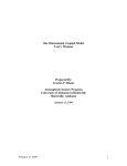
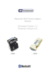
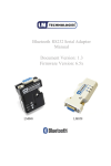
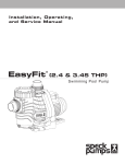
SAPPHIRE WATER CRO 4040-1 – CRO 4040-5 CommercialReverseOsmosisUnits General Operation & Installation Manual SAPPHIRE Commercial Reverse Osmosis Units If you need to call in for Technical support Please reference the following information for future reference. Also please see the technical acquisition form at the back of this manual for further assistance. Model # _____________________________________________________________________ Serial # ______________________________________________________________________ Date of Purchase: ______________________________________________________________ Note: The serial number is located in the front center of the RO panel. SAPPHIRE WATER 105 1st Ave. SW • Watson, SK • S0K 4V0 Phone (306).287.3633 • Toll Free 800.205.3633 • Fax (306).287.3795 SAPPHIRE WATER CRO 4040-1 – CRO4040-5 General Operation and Specifications Congratulations for purchasing a SAPPHIRE Commercial Reverse Osmosis System. This unit was specifically designed with you, our customer in mind. Top quality products and years of research and testing have gone into each SAPPHIRE unit to give you years of trouble free operation. SAPPHIRE products include a whole family of water treatment equipment, including softeners, iron filters; residential and commercial reverse osmosis equipment, carbon, sand and multi media filters and many more products. SAPPHIRE CRO 4040-1 – 4040-5 units are floor mounted for ease of installation. It is complete and ready for operation when the feed water supply and electrical connections are completed. SEE CONTROLLER MANUAL. Operation The SAPPHIRE Reverse Osmosis system is fully automatic when used with a storage tank and level control (see diagram). The system requires little attention and maintenance. The SAPPHIRE Reverse Osmosis system operates by the principle of reverse osmosis. The feed water passes through a 5-micron pre filter which removes suspended particles larger than 5 microns in size. The feed water is then fed into a booster pump that boosts the water pressure from the line pressure up to 150 to 200 psi. The pressurized water enters the membrane(s). The membrane(s) separate the water into two streams; product (permeate) and waste (concentrate) water. The product water has passed through the membrane(s), leaving behind 99% of any attached ions. The wastewater is a concentrated solution that carries the ions left behind by the product water. When the wastewater leaves the membrane(s), a portion of it goes through a recycle valve and goes across the membrane(s) again. The remaining wastewater goes through a concentrate valve and then to drain. Some SAPPHIRE units are equipped with a recycle valve for maximum water savings. If there is no recycle valve on a Reverse Osmosis unit, the waste to product ratio would be 5:1. The recycle valve enables the ratio to be 1:1. 2 GENERAL OPERATION & INSTALLATION MANUAL sap0060504-002 SAPPHIRE WATER CRO 4040-1-CRO 4040-5 Specifications Maximum Applied Pressure 225 psi Normal Operating Pressure 150 – 200 psi Maximum Operating Temperature 100° F Feed Water pH Range 3.0 - 10.0 Maximum Feed Water Turbidity 5 NTU Maximum Feed Water S.D.I. (15 min.) 4.0 Feed water Chlorine Concentration < 0.1 ppm Maximum Ratio of Concentrate to Permeate Flow 5:1 Mechanical Installation Pre treatment requirements vary. A complete water analysis should be conducted before installation and pre treatment recommendations made by your SAPPHIRE dealer. Note: Chlorine must be removed prior to water reaching the RO system. Mount system on the floor or a secure stand. 1. Connect a ball valve (1/2” min.) to the inlet side of the pre filter. Connect feed water line to the ball valve. 2. Provide piping from the concentrate outlet to drain. Drain must be equipped with a “P” trap or air gap. Do not install a shut off valve downstream of the Concentrate control valve. 3. Provide piping from the product outlet to the storage tank. Product water should enter the storage tank in through the top of the tank. An air gap should be provided from the water level to product outlet. (See Diagram). Storage tank should have a liquid level control provided to operate the Reverse Osmosis unit. When the control goes down with the water level, 3 GENERAL OPERATION & INSTALLATION MANUAL sap0060504-002 SAPPHIRE WATER CRO 4040-1-CRO 4040-5 it will turn the power to the RO unit on. When the water level is up to the desired setting, the liquid level switch will cut the power to the RO unit. To Start Unit 1. Open the water supply valve to the unit. Make sure that both the Recycle valve and Concentrate valve are fully open. 2. Proper electrical connections should be done. Plug the unit in. “OFF” should read on display. If a float switch is being used, proper connections should be done by connecting black and white wires to the wires marked tank full. Unit will start and have three “- - -“ while purging (delayed start). This is a delayed start to allow water to get to the pump before pump start up. Some units will show “FLS” and have a limited flush. Note: Units equipped with a 2005 computer chip on the circuit board will have a delayed start, solenoid valve will open and unit will purge for 5seconds. The Unit will then start and some units will display “FLS”. Unit will flush for 5 minutes and run for 2 hours and flush again continuously. No adjustments can be made regarding time on flush or run. Units equipped with a 2004 chip (Standard) will purge for 5 seconds and show TDS reading, three chips are available with permeate or auto flush boxes. Refer to R&D Specialties controller manual for flush modes or types. 3. After the unit has run for at least 1 minute, turn the Concentrate valve slowly clockwise until your concentrate flow rate is 2:1 with the permeate flow rate. Then turn the Recycle valve slowly clockwise until the membrane pressure is at factory operating specs. (See chart). These two valves adjust the flow rate and pressure. If you have your desired pressure, but the concentrate flow is too high, simply open the Recycle valve until the membrane pressure drops 10 psi. Close the Concentrate valve until the concentrate flow drops to the desired setting, or the membrane pressure rises 10 psi. If the desired setting is still not achieved, repeat the above steps until your unit is set. Note: It is recommended that the concentrate/permeate ratio be 2:1. The ratio can be set down to 1:1 by your SAPPHIRE dealer only with permission from the factory. Failure to comply with these ratios could void your warranty. 4. Check entire system for leaks. 4 GENERAL OPERATION & INSTALLATION MANUAL sap0060517-002 SAPPHIRE WATER CRO 4040-1-CRO 4040-5 Maintenance 1. Check membrane pressure gauge regularly to see that the system pressure is operating according to factory specs. 2. It is good practice to “Fast Flush” the membrane(s) once per week by opening the Concentrate valve fully for 15 minutes to rinse built up scale and solids from the membrane surface. 3. It is good practice to log as much data as possible at least on a weekly basis, e.g. feed pressure, membrane pressure, permeate flow, concentrate flow, feed water temp. For your convenience, an initial data log is included with this manual. Troubleshooting Refer to the R&D Manual that was included with your unit; for the troubleshooting guide. Refer to R & D Specialties Controller Manual for Specific Settings on S-100, S150 and the S-250. Manuals can be located on the R&D website at rdspec.ca under the tech support section. Pick the manual that refers to your specific unit. 5 GENERAL OPERATION & INSTALLATION MANUAL sap0060517-002 SAPPHIRE WATER CRO 4040-1-CRO 4040-5 Reverse Osmosis Data Sheet DATE WATER TEMP. FEED PRESSURE MEMBRANE PRESSURE PERMEATE CONCENTRATE FLOW FLOW 6 GENERAL OPERATION & INSTALLATION MANUAL sap0060517-002 SAPPHIRE WATER CRO 4040-1-CRO 4040-5 Typical Reverse Osmosis Installation 7 GENERAL OPERATION & INSTALLATION MANUAL sap0060517-002 SAPPHIRE WATER CRO 4040-1-CRO 4040-5 CRO 2600 CHART CRO 4040-1 FlowFLOW Chart PRODUCT WATER 1. FEED SUPPLY 8. CONCENTRATE VALVE 2. INLET SOLENOID VALVE 9. PRODUCT(PERMEATE) WATER 3. BOOSTER PUMP 10. WASTE(CONCENTRATE) WATER 4. MEMBRANE PRESS URE GAUGE 5. FEED WATER PRESSURE GAUGE 6. MEMBRANE AND HOUSING 7. WASTE WATER RECYCLE VALVE 8 GENERAL OPERATION & INSTALLATION MANUAL sap0060517-002 SAPPHIRE WATER CRO 4040-1-CRO 4040-5 CRO 4040-2 Flow Chart CRO 5200 FLOW CHART 9 PRODUCT WATER 1. FEED SUPPLY 8. CONCENTRATE VALVE 2. INLE T SOLENOID VALVE 9. PRODUCT(PE RMEATE) WATER 3. BOOSTER PUMP 10. WASTE(CONCENTR ATE) WATER 4. MEMBRANE PRES SURE GAUGE 5. FEED WATE R PRESSURE GAUGE 6. MEMBRANE AND HOUSING 7. WASTE WATER RECYCLE VALV E 9 GENERAL OPERATION & INSTALLATION MANUAL sap0060517-002 SAPPHIRE WATER CRO 4040-1-CRO 4040-5 CRO 4040-3 Flow Chart CRO 7800 FLOW CHART 10. WASTE(CONCENTRATE) WATER 5. FEED WATER PRESSURE GAUGE 7. WASTE WATER RECYCLE VALVE 10 GENERAL OPERATION & INSTALLATION MANUAL sap0060517-002 SAPPHIRE WATER CRO 4040-1-CRO 4040-5 CRO 4040-4 Flow Chart CRO 10400 FLOW CHART 9 11 12 PRODUCT WATER 1. FEED SUPPLY 2. INLET SOLENOID VALVE 3. BOOSTER PUMP 8. CONCENTRATE VALVE 9. PRODUCT FLOWMETER 10. WASTE(CONCENTRATE) WATER 4. MEMBRANE PRESSURE GAUGE 5. FEED WATER PRESSURE GAUGE 11. AUTO FLUSH VALVE 6. MEMBRANE AND HOUSING 12. RECYCLE WATER FLOWMETER 7. WASTE WATER RECYCLE VALVE 11 GENERAL OPERATION & INSTALLATION MANUAL sap0060517-002 SAPPHIRE WATER CRO 4040-1-CRO 4040-5 Technical Support Fax this form to your Dealer Technical Support Calls will be made ASAP. Please Keep in mind any time Difference Please Print Clearly Date: ________________ Company Name: _____________________________________ Contact Name: _______________________________ Dealer Name: _______________________________________ Dealer Contact: _______________________________ Phone: ____________________________________________ Fax: ___________________________________________ Model #: _____________________ Serial #: ______________________ Date Purchased: ______________________ Voltage: _________________ Other Features: __________________________________________________________ Standard Auto Flush Permeate Flush 8” x 5” box size 8” x 6” 8” x 10” 10” x 12” S100 Electrical Box S150 Electrical Box Other Red Dot Blue Dot Yellow Dot No Dot (Refers to the colored dot on the main computer chip in the Electrical Box) Specific Problem (Use a second sheet if needed): _____________________________________________________ ___________________________________________________________________________________________________ ___________________________________________________________________________________________________ ___________________________________________________________________________________________________ ___________________________________________________________________________________________________ ___________________________________________________________________________________________________ ___________________________________________________________________________________________________ ___________________________________________________________________________________________________ ___________________________________________________________________________________________________ ___________________________________________________________________________________________________ SAPPHIRE WATER ___________________________________________________________________________________________________ 105 1st Ave SW, Watson, SK S0K 4V0 Tel: (306).287.3633 Toll Free: 800.205.3633 Fax: (306).287.3795 ___________________________________________________________________________________________________ ___________________________________________________________________________________________________ ___________________________________________________________________________________________________ 12 GENERAL OPERATION & INSTALLATION MANUAL ___________________________________________________________________________________________________ sap0060517-002 SAPPHIRE WATER CRO 4040-1-CRO 4040-5 Warranty SAPPHIRE warrants its equipment against defects in workmanship and materials for a period of one (1) year from date of purchase of equipment by the customer. Such equipment must be used strictly in accordance with instructions furnished by manufacturer and for the purposes disclosed at the time of purchase. Liability of the company shall be limited to the replacement or repair, F.O.B. Watson, Saskatchewan, Canada of any defective equipment or part which, having been inspected by the manufacturer and determined, in the company’s sole judgment, as requiring replacement or repair because of defects in original workmanship and/or materials. Should membrane material or workmanship prove faulty, it will be covered by the warranty of the membrane manufacturer. No other warranties are expressed or implied. The purchaser is urged to keep accurate records of the operation of the unit. This will serve to protect his/her interests and greatly expedite replacement should it be required. 13 GENERAL OPERATION & INSTALLATION MANUAL sap0060517-002 14