1
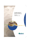
Royal GVS-65, Gas Venting System
Royal Pipe Systems has developed GVS-65 and GVS-90, complete PVC and CPVC
pipe systems designed for use as Type BH, Class IIA and B gas venting systems with
temperature ratings of up to and including 65° C (G VS-65) and 90°C (GVS-90). Royal
GVS-65 and GVS-90 have been third party certified to ULC S636. GVS-65/90 require
zero clearance to combustible construction.
These systems include fittings, pipe, solvent cement and primer. Only GVS-65/90
components may be used as part of these systems-do not use fittings, pipe, solvent
cement or primer from any other manufacturer with the Royal GVS-65/90 systems. Do
not mix pipe, fittings or joining methods from different manufacturers.
GVS-65 pipe and fittings (PVC) are white in colour. GVS-65 (PVC) solvent cement is
grey in colour and GVS-65/90 primer is purple.
GVS-90 (CPVC) pipe and fittings are grey in colour. GVS-90 (CPVC) solvent cement is
orange in colour and GVS-65/90 primer is purple.
Prior to the start of installation, all components must be examined for possible damage
due to shipping.
Proper joint construction is essential for safe installation and operation. The joint
construction procedure included in these instructions shall be followed exactly as written
for assembly of Royal GVS-65/90. Check for proper joint construction when joining pipe
to fittings.
These venting systems must be free to expand and contract and must be supported in
accordance with these instructions. Check for unrestricted vent movement through
walls, ceilings and roof penetrations.
Page 1 of 18
For Information, Call:
Royal Pipe Systems, 1-800-262-2353
131 Regalcrest Court, Woodbridge, Ontario
L4L 8P3
Issued: May 29 2007
Revision: 4, June 17, 2010
Installation shall comply with the latest edition of CAN/CSA-B149.1 including
supplements, the gas appliance manufacturer’s installation instructions and local
building codes, and shall be undertaken by qualified personnel.
All system installations shall be inspected by a qualified inspector prior to being placed
into operation and at least once per year after start of operation, as per the authority
having jurisdiction.
Vent piping which penetrates fire separations in buildings shall be properly firestopped in
accordance with the applicable standards.
Prior to installation of these systems, the authority having jurisdiction (such as gas
inspection authority, municipal building department, fire department, fire prevention
bureau, etc.) should be consulted to determine the need to obtain a permit.
Acceptance of these systems is dependent upon full compliance with the installation
instructions.
The safe operation of a system is based on the use of parts supplied by the
manufacturer and the performance of the system may be affected if the combination of
these parts is not used in actual building construction.
All framing of openings in walls, roofs, ceilings and floors shall be as per the applicable
code.
Venting:
All installations of vent piping shall be according to CAN/CSA-B149.1 and the gas
appliance manufacturer’s installation instructions, and shall comply with all other
Page 2 of 18
For Information, Call:
Royal Pipe Systems, 1-800-262-2353
131 Regalcrest Court, Woodbridge, Ontario
L4L 8P3
Issued: May 29 2007
Revision: 4, June 17, 2010
applicable codes. Vent piping which runs through unconditioned spaces must be
insulated.
Horizontal:
Horizontal piping must slope back towards the appliance with a minimum slope of 20mm
per 1000 mm to allow condensate to drain toward the appliance. Consult the appliance
manufacturer’s installation instructions for further details regarding the installation of
condensate drain fittings.
Horizontal piping must be supported by ¾” steel str aps, placed a minimum of every 1.2
metres. Supports must be installed such that movement due to expansion and
contraction can occur.
Vertical:
In the case of vertical piping in a multiple storey structure, the pipe shall be supported at
its base and at the floor level of alternate storeys above the base by anchors that can
bear the weight of pipe above it.
Expansion and Contraction:
Pipe products expand and contract with changes in temperature. This variation in length
depends on the coefficient of thermal expansion of the pipe material. Different pipe
diameters or wall thicknesses do not change the rate of thermal expansion or contraction
for each pipe material.
The Coefficient of Thermal Expansion for PVC is as follows:
3 x 10⁻⁵ in (expansion/contraction) / in (pipe length) / oF (change in temperature),
5.4 x 10⁻⁵ mm (expansion/contraction) / mm (pipe length) / oC (change in temperature)
The following tables give values for expansion/contraction for different changes in
temperature and lengths of PVC pipe runs.
Page 3 of 18
For Information, Call:
Royal Pipe Systems, 1-800-262-2353
131 Regalcrest Court, Woodbridge, Ontario
L4L 8P3
Issued: May 29 2007
Revision: 4, June 17, 2010
Expansion/Contraction of PVC (mm)
Length of Pipe Run (m)
∆T
(°C)
5
10
15
20
25
30
35
40
45
50
∆ T (°F)
5
10
15
20
25
30
35
40
45
50
2
4
6
8
10
12
14
16
18
20
0.54
1.08
1.62
2.16
2.70
3.24
3.78
4.32
4.86
5.40
1.08
2.16
3.24
4.32
5.40
6.48
7.56
8.64
9.72
10.80
1.62
3.24
4.86
6.48
8.10
9.72
11.34
12.96
14.58
16.20
2.16
4.32
6.48
8.64
10.80
12.96
15.12
17.28
19.44
21.60
2.70
5.40
8.10
10.80
13.50
16.20
18.90
21.60
24.30
27.00
3.24
6.48
9.72
12.96
16.20
19.44
22.68
25.92
29.16
32.40
3.78
7.56
11.34
15.12
18.90
22.68
26.46
30.24
34.02
37.80
4.32
8.64
12.96
17.28
21.60
25.92
30.24
34.56
38.88
43.20
4.86
9.72
14.58
19.44
24.30
29.16
34.02
38.88
43.74
48.60
5.40
10.80
16.20
21.60
27.00
32.40
37.80
43.20
48.60
54.00
10
0.02
0.04
0.05
0.07
0.09
0.11
0.13
0.14
0.16
0.18
Expansion/Contraction of PVC (in)
Length of Pipe Run (ft)
15
20
25
30
35
0.03
0.04
0.05
0.05
0.06
0.05
0.07
0.09
0.11
0.13
0.08
0.11
0.14
0.16
0.19
0.11
0.14
0.18
0.22
0.25
0.14
0.18
0.23
0.27
0.32
0.16
0.22
0.27
0.32
0.38
0.19
0.25
0.32
0.38
0.44
0.22
0.29
0.36
0.43
0.50
0.24
0.32
0.41
0.49
0.57
0.27
0.36
0.45
0.54
0.63
40
0.07
0.14
0.22
0.29
0.36
0.43
0.50
0.58
0.65
0.72
45
0.08
0.16
0.24
0.32
0.41
0.49
0.57
0.65
0.73
0.81
50
0.09
0.18
0.27
0.36
0.45
0.54
0.63
0.72
0.81
0.90
5
0.01
0.02
0.03
0.04
0.05
0.05
0.06
0.07
0.08
0.09
The Coefficient of Thermal Expansion for CPVC is as follows:
3.8 x 10⁻⁵ in (expansion/contraction) / in (pipe length) / oF (change in temperature),
6.8 x 10⁻⁵ mm (expansion/contraction) / mm (pipe length) / oC (change in temperature)
The following tables give values for expansion/contraction for different changes in
temperature and lengths of CPVC pipe runs.
Page 4 of 18
For Information, Call:
Royal Pipe Systems, 1-800-262-2353
131 Regalcrest Court, Woodbridge, Ontario
L4L 8P3
Issued: May 29 2007
Revision: 4, June 17, 2010
∆ T (°C)
5
10
15
20
25
30
35
40
45
50
∆ T (°F)
5
10
15
20
25
30
35
40
45
50
2
0.68
1.36
2.04
2.72
3.40
4.08
4.76
5.44
6.12
6.80
5
0.01
0.02
0.03
0.05
0.06
0.07
0.08
0.09
0.10
0.11
4
1.36
2.72
4.08
5.44
6.80
8.16
9.52
10.88
12.24
13.60
Expansion/Contraction of CPVC (mm)
Length of Pipe Run (m)
6
8
10
12
14
2.04
2.72
3.40
4.08
4.76
4.08
5.44
6.80
8.16
9.52
6.12
8.16
10.20
12.24
14.28
8.16
10.88
13.60
16.32
19.04
10.20
13.60
17.00
20.40
23.80
12.24
16.32
20.40
24.48
28.56
14.28
19.04
23.80
28.56
33.32
16.32
21.76
27.20
32.64
38.08
18.36
24.48
30.60
36.72
42.84
20.40
27.20
34.00
40.80
47.60
16
5.44
10.88
16.32
21.76
27.20
32.64
38.08
43.52
48.96
54.40
18
6.12
12.24
18.36
24.48
30.60
36.72
42.84
48.96
55.08
61.20
20
6.80
13.60
20.40
27.20
34.00
40.80
47.60
54.40
61.20
68.00
10
0.02
0.05
0.07
0.09
0.11
0.14
0.16
0.18
0.21
0.23
Expansion/Contraction of CPVC (in)
Length of Pipe Run (ft)
15
20
25
30
35
0.03
0.05
0.06
0.07
0.08
0.07
0.09
0.11
0.14
0.16
0.10
0.14
0.17
0.21
0.24
0.14
0.18
0.23
0.27
0.32
0.17
0.23
0.29
0.34
0.40
0.21
0.27
0.34
0.41
0.48
0.24
0.32
0.40
0.48
0.56
0.27
0.36
0.46
0.55
0.64
0.31
0.41
0.51
0.62
0.72
0.34
0.46
0.57
0.68
0.80
40
0.09
0.18
0.27
0.36
0.46
0.55
0.64
0.73
0.82
0.91
45
0.10
0.21
0.31
0.41
0.51
0.62
0.72
0.82
0.92
1.03
50
0.11
0.23
0.34
0.46
0.57
0.68
0.80
0.91
1.03
1.14
Page 5 of 18
For Information, Call:
Royal Pipe Systems, 1-800-262-2353
131 Regalcrest Court, Woodbridge, Ontario
L4L 8P3
Issued: May 29 2007
Revision: 4, June 17, 2010
The following are suggestions for accommodating expansion/contraction with
PVC/CPVC pipe:
•
Pipe supports should be installed loosely enough to allow linear movement of
pipe.
•
Properly designed offsets should be used to accommodate
expansion/contraction for long pipe runs.
•
Pipe should not be anchored rigidly in walls or against joists-pipe must be
allowed to move freely at every support location.
Vent Termination:
General:
The venting system shall terminate in accordance with the requirements of CAN/CSA
B149.1, the gas appliance manufacturer’s installation instructions and the local building
code.
A venting system shall not terminate (CAN/CSA B149.1):
•
less than 7 ft above a paved sidewalk or a paved driveway that is located on
public property;
•
within 6 ft of a mechanical air-supply inlet to any building;
•
above a meter and regulator assembly within 3 ft horizontally of the vertical
centerline of the regulator vent outlet to a maximum vertical distance of 15 ft;
•
within 3 ft of any gas service regulator vent outlet;
•
less than 1 ft above grade level;
•
within 6 in (inputs up to and including 10,000 Btuh), 12 in (inputs from 10,000
Btuh to 100,000 Btuh inclusive) and 3 ft (inputs exceeding 100,000 Btuh) of a
window or door that can be opened in any building, of any non-mechanical airsupply inlet to any building, or of the combustion air inlet of any other appliance;
•
underneath a veranda, porch or deck unless they are open on a minimum of two
sides under the floor, or if the distance between the top of the vent termination
and the underside of the veranda, porch or deck is greater than 1 ft.
Page 6 of 18
For Information, Call:
Royal Pipe Systems, 1-800-262-2353
131 Regalcrest Court, Woodbridge, Ontario
L4L 8P3
Issued: May 29 2007
Revision: 4, June 17, 2010
Horizontal:
Horizontal vents should pass through the exterior wall of the building. Horizontal vent
termination shall be according to Figure 1 or Figure 2 (if adequate vertical clearance is
not available), or using the Royal GVS-65 Side Wall Vent Kit.
REDUCER
COUPLING
COMBUSTION AIR
VENT
2" Dia.
2" Dia.
12"
REDUCER
COUPLING
EXHAUST
VENT
2" Dia.
REDUCER
COUPLING
COMBUSTION AIR
VENT
EXHAUST
VENT
MIN. 12" ABOVE MAXIMUM GRADE
(INCLUDING SNOW ACCUMULATION)
Min. 8"
EXTERIOR
WALL
EXTERIOR
WALL
TOP VIEW
SIDE VIEW
Figure 1
EXHAUST
VENT
REDUCER
COUPLING
12"
COMBUSTION AIR
VENT
COMBUSTION AIR
VENT
2" Dia.
12"
2" Dia.
EXHAUST
VENT
2" Dia.
REDUCER
COUPLING
REDUCER
COUPLING
MIN. 12" ABOVE MAXIMUM GRADE
(INCLUDING SNOW ACCUMULATION)
Min. 8"
EXTERIOR
WALL
EXTERIOR
WALL
SIDE VIEW
TOP VIEW
Figure 2
Page 7 of 18
For Information, Call:
Royal Pipe Systems, 1-800-262-2353
131 Regalcrest Court, Woodbridge, Ontario
L4L 8P3
Issued: May 29 2007
Revision: 4, June 17, 2010
Royal GVS-65 Side Wall Vent Kit:
Royal offers a vent termination kit to be used with our Class IIA (PVC) gas venting
system for horizontal vent terminations. This kit is available for 2” and 3” horizontal vent
terminations.
This vent kit is to be used with Category IV condensing furnaces only. Do not use
with Category I, II or III furnaces.
The vent kit provided includes:
1-Vent Terminal Base
1-Vent Termination Cap
4-#8 x 1” SS Screws
4-#8 x 2” SS Screws
4-Plastic Screw Anchors
1-Instruction Sheet
Side Wall Vent Kit Installation:
1
Determine the best location for the vent terminal. In addition to all
applicable codes, consider the following:
a.
Minimize the length of pipe and fittings in the piping. Consult the
appliance installation manual to determine maximum length of
pipe and fittings allowed.
b.
Terminal kit should be positioned where vent vapors will not
damage plants, shrubs, building materials, air-conditioning
equipment, or where the vapors might be objectionable.
c.
Terminal kit should be located where it will not be affected by wind
gusts, snow build up, leaves or other debris that will inhibit the
function of the vent exhaust or intake.
Page 8 of 18
For Information, Call:
Royal Pipe Systems, 1-800-262-2353
131 Regalcrest Court, Woodbridge, Ontario
L4L 8P3
Issued: May 29 2007
Revision: 4, June 17, 2010
2.
Vent may be oriented in any direction as long as it is mounted on a
vertical wall (See Figure 3).
Figure 3
3.
If multiple vent kits are being installed, there must be at least 16”
horizontal space between the vent caps. To prevent the possibility of
condensate freeze-up, do no locate the vent kits above one another.
4.
Use the vent base as a template to locate the vent and intake holes and
four mounting holes. Cut two 3-7/8” diameter holes for the exhaust and
intake pipes. Drill four 3/16” diameter holes for the mounting screws.
Insert plastic anchors in holes. Attach vent base to wall with 4-#8 x 2” SS
screws.
5.
Assemble the vent cap to the vent base with 4-#8 x 2” SS screws.
Do not operate the furnace without the vent cap in place.
Recirculation of combustion products may occur resulting in
equipment damage, personal injury or death.
6.
Install the exhaust and intake piping through the wall into the vent
termination kit. Use RTV silicon sealant to seal the pipe to the vent cap,
Page 9 of 18
For Information, Call:
Royal Pipe Systems, 1-800-262-2353
131 Regalcrest Court, Woodbridge, Ontario
L4L 8P3
Issued: May 29 2007
Revision: 4, June 17, 2010
to allow future disassembly and cleaning. Do not use PVC solvent
cement or primer.
7.
Seal gap between pipes and wall with expanding foam or other suitable
material.
8.
Extend intake and exhaust pipes to appliance, making sure to attach
intake and exhaust to the correct sides of the vent cap. Use only Royal
GVS-65, PVC pipe, fittings, primer and solvent cement.
9.
Operate appliance for a minimum of 15 minutes to ensure that it works
properly and that all piping joints are sealed, to prevent the escape of
combustion products into the home.
Figure 4 shows the installation of the side wall vent kit.
Figure 4
Page 10 of 18
For Information, Call:
Royal Pipe Systems, 1-800-262-2353
131 Regalcrest Court, Woodbridge, Ontario
L4L 8P3
Issued: May 29 2007
Revision: 4, June 17, 2010
Vertical:
Vent piping can also be installed in a vertical position with the vent terminating through
the roof. In this instance, all framing, firestopping and flashing shall be installed as per
the local building code.
10 ft
2" Dia.
min. 12"
min. 2 ft
2" Dia.
min. 12"
max. 3"
Reducer
Coupling
)
tion
Unconditioned Space
Framing, Firestopping and
Flashing as per the local
Building Code
Exhaust Vent
Combustion Air Vent
Reducer
Coupling
wA
ine Sno
L
g
of
Ro cludin
n
(I
la
mu
u
c
c
Figure 5
Joint Construction
General:
•
Use only Royal Pipe Systems GVS-65/90 primer and solvent cements.
•
Use solvent cement and primer prior to expiration date marked on container.
•
Above 0° C ambient temperature, joints may be assem bled without the use of
primer, provided adequate penetration and softening of the pipe/fitting surface
can be achieved with solvent cement alone.
Page 11 of 18
For Information, Call:
Royal Pipe Systems, 1-800-262-2353
131 Regalcrest Court, Woodbridge, Ontario
L4L 8P3
Issued: May 29 2007
Revision: 4, June 17, 2010
Solvent Cementing Procedure, With Primer:
1. Assemble materials for the job, including correct solvent cement, primer
and correctly sized applicator.
2. Cut pipe as square as possible using a hand saw and miter box or
mechanical saw. Do not use a diagonal cut, as it reduces the bonding
area in the joint.
3. If plastic tubing cutters are used, care must be taken to remove any
raised bead at the end of the pipe, caused by cutting. A file or reamer
may be used to remove the bead.
4. Use a knife, file or reamer to remove burrs from the inside and outside of
the pipe end, as these will hinder the integrity of the joint. All sharp edges
should be removed from the inside and outside edges of the pipe to
prevent the pipe from pushing the solvent cement into the fitting socket,
thereby causing a weak spot to form. The pipe end should be chamfered,
as shown in Figure 6.
10 - 15°
Figure 6
5. All dirt, grease and moisture should be removed from the pipe and socket
by thoroughly wiping with a clean, dry cloth.
6. Dry fit pipe and fitting joints prior to cementing. For proper interference fit,
the pipe should go easily into the socket approximately 1/3 to 2/3 of the
socket depth. If this is not the case, other pipe or fittings should be used.
Page 12 of 18
For Information, Call:
Royal Pipe Systems, 1-800-262-2353
131 Regalcrest Court, Woodbridge, Ontario
L4L 8P3
Issued: May 29 2007
Revision: 4, June 17, 2010
7. The applicator should be sized according to the size of pipe and fittings
being joined. The brush width of the applicator should be equal to
approximately ½ of the pipe diameter.
8. Primer is used to penetrate and soften the surfaces so that they will fuse
together under a wide variety of conditions. The penetration or softening
can be checked by dragging the edge of a knife or sharp object over the
coated surface. If a few thousandths of an inch of the primed surface can
be scratched or scraped away, proper penetration has occurred. Varying
weather conditions affect priming and cementing action and may require
more time or repeated applications to either or both surfaces.
9. Using the correct applicator size (see # 7), aggressively work the primer
into the socket, keeping the surface and applicator wet until the surface
has softened, re-dipping the applicator as required. When the surface is
primed, remove any puddles of primer from the socket.
10. Aggressively work the primer on to the end of the pipe, to a point ½”
beyond the depth of the socket.
11. Perform a second application of primer in the socket.
12. While the surfaces are still wet, the appropriate solvent cement should be
applied.
13. Using the correct applicator size, aggressively work a full, even layer of
cement onto the pipe end to a point equal to the depth of the socket. Do
not brush out to a thin paint type layer, as this will dry within a few
seconds.
14. Aggressively work a medium layer of cement into the fitting socket; avoid
puddling cement in the socket. On the pipe end, do not coat beyond the
socket depth or allow cement to run down into the pipe beyond the
socket.
15. Apply a second full, even layer of cement on the pipe.
Page 13 of 18
For Information, Call:
Royal Pipe Systems, 1-800-262-2353
131 Regalcrest Court, Woodbridge, Ontario
L4L 8P3
Issued: May 29 2007
Revision: 4, June 17, 2010
16. Immediately, while the cement is still wet, assemble the joint. Use
enough force to ensure that the pipe is fully inserted into the socket.
Twist the pipe a ¼ turn as it is being inserted.
17. Hold the joint together for approximately 30 seconds to avoid push out.
18. After assembly, inspect the joint to ensure that there is a ring or bead of
cement completely around the juncture of the pipe and socket. If there
are voids in this ring, sufficient cement was not applied and the joint may
be defective.
19. Remove the excess cement from the pipe and socket (including the ring
or bead) using a cloth. Avoid disturbing or moving the joint.
20. Handle newly cemented joints with care until initial set has taken place.
Follow set and cure times before handling or testing the system.
Solvent Cementing Procedure, Without Primer:
1. Assemble materials for the job, including correct cement and correctly
sized applicator.
2. Cut pipe as square as possible using a hand saw and miter box or
mechanical saw. Do not use a diagonal cut, as it reduces the bonding
area in the joint.
3. If plastic tubing cutters are used, care must be taken to remove any
raised bead at the end of the pipe, caused by cutting. A file or reamer
may be used to remove the bead.
4. Use a knife, file or reamer to remove burrs from the inside and outside of
the pipe end, as these will hinder the integrity of the joint. All sharp edges
should be removed from the inside and outside edges of the pipe to
prevent the pipe from pushing the solvent cement into the fitting socket,
thereby causing a weak spot to form. The pipe end should be chamfered,
as shown in Figure 4.
Page 14 of 18
For Information, Call:
Royal Pipe Systems, 1-800-262-2353
131 Regalcrest Court, Woodbridge, Ontario
L4L 8P3
Issued: May 29 2007
Revision: 4, June 17, 2010
5. All dirt, grease and moisture should be removed from the pipe and socket
by thoroughly wiping with a clean, dry cloth.
6. Dry fit pipe and fitting joints prior to cementing. For proper interference fit,
the pipe should go easily into the socket approximately 1/3 to 2/3 of the
socket depth. If this is not the case, other pipe or fittings should be used.
7. The applicator should be sized according to the size of pipe and fittings
being joined. The brush width of the applicator should be equal to
approximately ½ of the pipe diameter.
8. The penetration or softening can be checked by applying a normal layer
of solvent cement to a scrap piece of pipe and dragging the edge of a
knife or sharp object over the coated surface. If a few thousandths of an
inch of the coated surface can be scratched or scraped away, proper
penetration has occurred. Varying weather conditions affect cementing
action and may require more time, repeated applications to either or both
surfaces or the use of primer.
9. Using the correct applicator size, aggressively work a full, even layer of
cement onto the pipe end to a point equal to the depth of the socket. Do
not brush out to a thin paint type layer, as this will dry within a few
seconds. Do not coat beyond the socket depth or allow cement to run
down into the pipe beyond the socket.
10. Aggressively work a medium layer of cement into the fitting socket; avoid
puddling cement in the socket.
11. Apply a second full, even layer of cement on the pipe to a point equal to
the depth of the socket.
12. Immediately, while the cement is still wet, assemble the joint. Use
enough force to ensure that the pipe is fully inserted into the socket.
Twist the pipe a ¼ turn as it is being inserted.
13. Hold the joint together for approximately 30 seconds to avoid push out.
Page 15 of 18
For Information, Call:
Royal Pipe Systems, 1-800-262-2353
131 Regalcrest Court, Woodbridge, Ontario
L4L 8P3
Issued: May 29 2007
Revision: 4, June 17, 2010
14. After assembly, inspect the joint to ensure that there is a ring or bead of
cement completely around the juncture of the pipe and socket. If there
are voids in this ring, sufficient cement was not applied and the joint may
be defective.
15. Remove the excess cement from the pipe and socket (including the ring
or bead) using a cloth. Avoid disturbing or moving the joint.
16. Handle newly cemented joints with care until initial set has taken place.
Follow set and cure times before handling or testing the system.
Set Times
Average Initial Set Times
Temperature Range
1 ½” – 2”
2 ½” to 4”
15o to 40o C
5 min.
30 min.
5o to 15o C
10 min.
2 hrs.
-16o to 5o C
15 min.
12 hrs.
Joint Cure Schedule
Average Joint Cure Schedule
Relative Humidity 60% or Less
Cure Time
Cure Time
Temperature Range During
Pipe Sizes
Pipe Sizes
Assembly and Cure Periods
1 ½” – 2”
2 ½” – 4”
15o to 40o C
30 min.
1 ½ hrs.
5o to 15o C
45 min.
4 hrs.
-16o to 5o C
1 hr.
12 hrs.
In damp or humid weather allow 50% more cure time.
Page 16 of 18
For Information, Call:
Royal Pipe Systems, 1-800-262-2353
131 Regalcrest Court, Woodbridge, Ontario
L4L 8P3
Issued: May 29 2007
Revision: 4, June 17, 2010
Estimated Solvent Cement Requirements
Average Number of Joints per Litre of Solvent Cement
Pipe/Fitting Diameter
1 ½”
2”
2 ½”
3”
4”
Number of Joints
90
60
40
40
30
Estimated Primer Requirements
Average Number of Joints per Litre of Primer
Pipe/Fitting Diameter
1 ½”
2”
2 ½”
3”
4”
Number of Joints
180
120
80
80
50
Solvent Cementing in Cold Weather:
•
Store pipe and fittings in a heated area. Prefabricate as much of the system as
possible in a heated area.
•
When not in use, store sealed solvent cement and primer between 5° C and 21°
C. Do not use open flame or electric heaters to warm cements and primers.
•
Take care to remove moisture, ice and snow from the mating surfaces.
Solvent Cementing in Hot Weather:
•
At the time of assembly, the surface temperature of the mating surfaces should
not exceed 45° C. Shade or shelter the joint surfa ces from direct sunlight for at
least 1 hour prior to joining and during the joining process. If necessary, swab
the mating surfaces with clean, wet rags to reduce the surface temperature
(thoroughly dry surfaces before applying primer or cement).
•
Make joints during the cooler early morning hours.
•
Apply cement quickly and join pipe to fitting as quickly as possible after applying
the cement.
Page 17 of 18
For Information, Call:
Royal Pipe Systems, 1-800-262-2353
131 Regalcrest Court, Woodbridge, Ontario
L4L 8P3
Issued: May 29 2007
Revision: 4, June 17, 2010
•
Keep solvent cement container closed or covered when not in use, to minimize
solvent loss.
Solvent Cementing in Wet Conditions:
•
Mating surfaces must be dry when the joint is made.
•
Work under a cover or canopy to keep rain off pipe and fittings.
•
Work quickly after drying the pipe and fitting to avoid condensation.
•
Allow a longer cure time before the system is tested or used.
Storage and Handling of Solvent Cement and Primer:
•
Solvent cement and primer contain highly flammable solvents. Follow all specific
safety precautions provided on container label and Material Safety Data Sheet.
•
Keep primer and solvent cement away from heat, sparks and open flame.
•
Keep containers tightly closed except when in use.
•
Ensure proper ventilation of work area and avoid inhaling solvent vapours.
•
Where the possibility of splashing exists, wear proper eye protection or a face
shield.
•
Avoid contact with skin.
Page 18 of 18
For Information, Call:
Royal Pipe Systems, 1-800-262-2353
131 Regalcrest Court, Woodbridge, Ontario
L4L 8P3
Issued: May 29 2007
Revision: 4, June 17, 2010