1
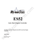
TSC3
Timer
Module
Installation and User Manual for the TSC3 Timer Module.
Full Version
File: TSC3rev1.0.doc
Sept. 3, 2004
2
READ MANUAL BEFORE INSTALLING UNIT
Receipt of shipment and warranty return information
Upon receipt of shipment, carefully remove the unit from the shipping container and thoroughly
examine the unit for shipping damage. In case of damage, immediately contact the carrier and
request that an inspection report be filed prior to contacting the COMPANY.
All returned items must be shipped prepaid and include a return material authorization (RMA)
number issued by the COMPANY. RMA forms are available by contacting the COMPANY.
Limited Warranty
The COMPANY (DynaGen Technologies Inc.) warrants the product with specifications as
explained herein. The COMPANY shall repair or replace any TSC3 controller, which prove to be
defective under normal and proper use within three years from the date of shipment. This
constitutes the only warranty and no other warranty shall be implied.
For questions or comments regarding this product, contact:
DynaGen Technologies Inc.
Phone (902) 562 0133
Fax: (902) 567 0633
Email: [email protected]
WEB SITE: www.dynagensystems.com
Operating & Installation Manual for the TSC3 Timer Module
3
Table of Contents
INTRODUCTION
4
SPECIFICATIONS
Wiring Guidelines
Terminal Description
Outline Dimension Drawing
4
5
6
7
TIMER SETTINGS
8
50/60 HERTZ SETTINGS
8
LOAD / NO LOAD SETTINGS
9
LED INDICATIONS
9
LOGIC SEQUENCE
10
Operating & Installation Manual for the TSC3 Timer Module
4
INTRODUCTION
The TSC3 Timer Module provides all the necessary timing functions for an automatic transfer
switch. The TSC3 can be used in conjunction with a variety of automatic transfer switches, and
eliminates the need for stand-alone timers.
SPECIFICATIONS
Operating VDC limits:
(3.75VDC min.- 30VDC max.)
Standby current draw:
12mA
Operating current draw:
175mA
Reverse polarity protected:
Internal protection will prevent damage to unit under a
reverse polarity condition. Re-connect power leads
properly, and normal operation will resume.
Speed sensing input accepts:
Generator AC output directly (50 or 60 Hz)
Speed sensing maximum rating:
Withstands Line voltage (300 V.A.C.)
Operating temperature range:
-40 O C ⇒ +85 O C
Operating humidity range:
0 ⇒ 95% non-condensing
Control Relay:
20 Amps max.
Annunciation outputs:
Sourcing (+bat) outputs (300mA max. per output)
Actual unit weight:
0.67 lb. (0.30kg)
Shipping weight:
1 lb. (0.45kg)
Unit dimensions:
3.302” x 3.342” x 1.8”
Shipping dimensions:
4” (10.16cm) x 4” (10.16cm) x 3” (7.62cm)
DC Transient Protection:
Withstands 1500V, 250 us
Encapsulation:
Sealed for environmental protection
Operating & Installation Manual for the TSC3 Timer Module
5
WIRING GUIDELINES
1. DO NOT use wire smaller than 18 AWG.
2. DO NOT exceed the maximum rated current and voltage on the Remote Start Contacts
(RSC1 & RSC2). Do not exceed 20 amps for RSC1 & RSC2, and 300 mA for the
annunciation outputs, 400 mA combined.
3. The annunciation outputs are internally protected against overload and short circuit (fault)
NOTE: When a fault appears on one of the annunciation outputs, only that specific output
becomes un-operable, all other annunciation outputs continue to operate. When fault is
removed, output resumes proper operation.
4. The remote start connections from the timer module are not fused in any way. If fusing is
required, use a 20 AMP automotive style fuse.
5. Do not switch AC voltages with remote start connections from timer module.
6. Annunciation outputs are for DC control only, and are source driven. DO NOT supply power
to, or attempt to drive AC coil relays with annunciation outputs. Always use clamping diodes
when driving inductive DC loads.
7. A 12 VDC relay must be installed for 12VDC systems, and a 24 VDC relay must be
installed for 24 VDC systems.
Operating & Installation Manual for the TSC3 Timer Module
6
TERMINAL DESCRIPTION
Term #
1
2
3
4
5
6
7
8
9
10
11
12
13
14
15
16
17
18
19
20
Description
RSC1, provided for the connection of one lead from the remote start contacts of
engine controller.
Battery ground connection for the timer module. A good ground connection,
directly from the battery, is required for proper operation.
Battery power terminal. When +12/24 VDC is applied, the timer module is in the
standby mode waiting for a Start/Stop signal.
Provided for connection of relay board auto start contacts to start the timer
module.
Provided for connection of relay board auto start contacts to start the timer
module.
Not used
RSC2, provided for the connection of one lead from the remote start contacts of
engine controller.
Provided for connection of exerciser output.
Engine Start time delay annunciation output
Normal to Emergency time delay annunciation output
Emergency to Normal time delay annunciation output
Engine Cool Down annunciation output
Generator Run annunciation output
Normal Disable- disables transfer from Emergency to Normal during timing
functions
Emergency Disable- disables transfer from Normal to Emergency during timing
functions
Common ground
Common ground.
Provided for connection of exerciser input.
Delay on Neutral Input
Not used
NOTE: If there is a requirement to disable the timer module, a switch must be installed to
disconnect the DC power to the timer module.
Four wires must be run to the engine control source on the generator. The wires to be connected
are:
1). Battery ground
2). Battery positive
3). Remote start contact (RSC1)
4). Remote start contact (RSC2)
Operating & Installation Manual for the TSC3 Timer Module
7
OUTLINE DIMENSIONS
Operating & Installation Manual for the TSC3 Timer Module
8
TIMER SETTINGS
All necessary timing functions are configurable through the use of on-board potentiometers
(POTS) and DIP switches. Each pot is a nominal 25 turns, and can be increased by turning the
pot clockwise (See DWG 517, page7 for reference).
The following adjustable timers are included in the TSC3.
1: TDES: Time Delay Engine Start: Adjustable from 0 to 32 Seconds. This delay is necessary to
prevent unnecessary engine starts. (Factory default setting – 10 seconds, pot resolution is 1.28
seconds per turn)
2: TDNE: Time Delay, Normal to Emergency: Adjustable from 0 to 32 seconds. This allows the
engine to stabilize before load transfer (factory default setting – 4 seconds, pot resolution is 1.28
seconds per turn).
3: TDEN: Time Delay, Emergency to Normal: Adjustable from 0 to 128 seconds. This allows a
delay after the utility returns, to insure it has indeed returned and stabilized (factory default
setting – 120 seconds, pot resolution is 5.12 seconds per turn).
4: TDEC: Time Delay, Engine Cool: Adjustable from 0 to 256 seconds. This allows the engine
to continue running for a set time after re-transfer of load to the utility, to circulate coolant for a
safe cool-down (factory default setting – 240 seconds, pot resolution is 10.24 seconds per turn).
5: Delay on Neutral: Adjustable from 0 to 35 seconds via DIP #1, 2, and 3. This will stop
transfer from Emergency to Normal power when both breakers are off for the Delay on neutral
time period.
50/60 HERTZ SETTING
The dipswitch located on the unit is used to set the Timer Module for 50 or 60 Hz systems.
When switch location #4 is on, the system is configured for 60 Hz. When switch location #4 is
off, the unit is configured for 50 Hz systems.
The 50 /60 Hz connection is used as follows:
After the expiration of the time delay Normal to Emergency, the engine controller verifies that
the frequency is above 55 Hz for a 60 Hz system, and above 45 Hz for a 50 Hz system. After the
Timer Module has verified that the frequency exceeds the frequency limits, the controller
proceeds to transfer to the Emergency source of power.
Operating & Installation Manual for the TSC3 Timer Module
9
LOAD / NO LOAD SETTING
The dipswitch located on the TSC3 is used to set the load / no load setting. When switch
location #6 is on, the system is configured for a load condition. When switch location #6 is off,
the unit is configured for a no load condition.
This setting applies to the engine exercise option only. This setting allows for exercising the
transfer switch under a loaded or a no load condition.
When exercising the transfer switch under a load condition the switch will transfer to generator
emergency power. When exercising the transfer switch under a no load condition the switch will
not transfer and stay in the normal power position.
LED INDICATIONS
LED DESCRIPTION
LED 1 (YELLOW)
LED 2 (RED)
LED 3 (GREEN)
LED 4 (YELLOW)
LED 5 (GREEN)
Indication
This indicates Time Delay Engine Start
(TDES). LED is illuminated during this
time delay period.
This indicates Time Delay Normal to
Emergency (TDNE). LED is illuminated
during this time delay period.
This indicates Time Delay Emergency to
Normal (TDEN). LED is illuminated during
this time delay period.
This indicates Time Delay Engine Cool
Down (TDEC). LED is illuminated during
this time delay period as well as during the
Delay on Neutral period.
This LED indicates that the remote start
contacts are closed and that the frequency
of the Emergency source has exceeded 20
Hz.
The timer module also provides for annunciation connections, which can drive remote LEDS.
These annunciation connections provide the same indication as LEDS on the timer module.
These annunciation outputs can deliver a maximum of 300 mA per output. NOTE: Do not
exceed 400 mA total for all outputs.
Operating & Installation Manual for the TSC3 Timer Module
10
LOGIC SEQUENCE
Upon a fault of the utility source, the timer module proceeds to a delay in engine starting
(TDES), and the yellow LED will illuminate. This time delay prevents unnecessary engine
starting and is adjustable from 0 to 32 seconds. If during the TDES the utility source returns to
normal, the timer module simply returns to a monitoring mode.
After the expiration of the TDES delay, the timer module closes the RS (remote start ) relay
contacts and initiates cranking of the engine. Once the engine starts, the timer module proceeds
to the time delay normal to emergency (TDNE), and the red LED will illuminate. This adjustable
time delay begins timing immediately after the engine running LED illuminates (speed exceeds
20 Hz). After the time delay has lapsed, the timer module ensures that the generator frequency is
within normal limits (> 55 HZ for 60 Hz systems, and > 45 HZ for 50 Hz systems). If the
generator frequency is above the low limit, the timer module signals the transfer switch to
immediately transfer to the generator source of supply.
Once the transfer switch has transferred to the generator source of supply, the timer module then
monitors for closure of the ATS (automatic transfer switch) start contacts. If the utility returns to
normal while the generator is running, the timer module proceeds to time-delay-emergency-tonormal (TDEN), and the green Led will illuminate. After the TDEN delay, the timer module
proceeds to signal the transfer switch to transfer to the utility source of supply. If the Delay on
neutral time is NOT set to zero (DIP # 1, 2, and 3 are OFF) then the transfer from Emergency
power to Normal power will be halted when both sources are cut out. The time when both
sources are out is set by the DIP’s.
After Delay on Neutral, the timer module proceeds to initiate transfer to the utility source. The
timer module then initiates an engine cool-down period (TDEC), and the yellow Led is
illuminated. The engine continues to run unloaded for the set time period. If the utility fails
during this set time period (auto start contacts close), the control module proceeds to transfer
back to the generator source after the preset time delay.
Operating & Installation Manual for the TSC3 Timer Module