1
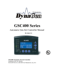
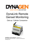
MD10 Engine Controller Installation and User Manual for the MD10 Engine Controller. Full Version File: MartinDieselMD10rev1.2.Doc June 12,2001 2 READ MANUAL BEFORE INSTALLING UNIT Receipt of shipment and warranty return information Upon receipt of shipment, carefully remove the unit from the shipping container and thoroughly examine the unit for shipping damage. In case of damage, immediately contact the carrier and request that an inspection report be filed prior to contacting the COMPANY. All returned items must be shipped prepaid and include a return material authorization (RMA) number issued by the COMPANY. RMA forms are available by contacting the COMPANY. Limited Warranty The COMPANY (DynaGen Technologies Inc.) warrants the product with specifications as explained herein. The COMPANY shall repair or replace any MD10 controller, which prove to be defective under normal and proper use within three years from the date of shipment. This constitutes the only warranty and no other warranty shall be implied. For questions or comments regarding this product, contact: DynaGen Technologies Inc. Phone (902) 562 0133 Fax: (902) 567 0633 Email: [email protected] WEB SITE: www.dynagensystems.com ______________________________________________________________________________________ Operating & Installation Manual for the Martin Diesel MD10 Engine Controller 3 Table of Contents INTRODUCTION 4 SPECIFICATIONS 5 WIRING INSTALLATION GUIDELINES Wiring instructions, types and sizes Outline Dimension Drawing Wiring Guidelines General Wiring Diagram 6 6 7 8 9 LED INDICATIONS 10 ADJUSTMENTS AND SETUP PROCEDURES Select the engine speed range Crank Limiter calibration Crank Disconnect calibration Over-speed calibration 11 11 12 12 13 TROUBLESHOOTING GUIDELINES 14 ______________________________________________________________________________________ Operating & Installation Manual for the Martin Diesel MD10 Engine Controller 4 INTRODUCTION The MD10 provides start/stop protection control for all types of engine-driven equipment. Simplicity of use, safety, features, versatility and over-all quality are paramount, providing the most cost-effective and reliable solution available. Ours came to be one of the smallest controllers available, with the best value per dollar-cost, backed by a 3 year warranty. • "No speed signal" detection: Should the frequency of the speed sensing signal go to zero while the engine is running, a No Speed Failure is asserted, and specifically indicated. • Two selectable speed ranges: Allows for multiple speed signal use, such as 1) Magnetic pickup sensor, 2) Alternator output, 3) direct generator output connection. • REPLACEABLE RELAYS; Replaceable relays provided within on board sockets. Relays Rated 20 Amps at 30 VDC • REPLACEABLE FUSE; On board replaceable 20A fuse, mini-fuse (standard automotive type). • Reversed supply protection; No requirement for series diode on supply. • 3.3V to 30V, -40ºc. to +85ºc. operation: Works anywhere; any-time . • Zero Speed Restart: Prevents starter pinion wear by ensuring that no engagement of the starter is possible unless the engine is stopped. • Oil Bypass Failure: Waits 15 seconds from start for 1-3 crank tries, and 20 seconds for more than 3 crank tries, before enabling Low Oil pressure monitoring. Requires no user setting. • Rest-Time indication: Provides feedback between crank attempts. • SMALL SIZE; 3.302” x 3.342” x 1.842” 0.67lbs ______________________________________________________________________________________ Operating & Installation Manual for the Martin Diesel MD10 Engine Controller 5 SPECIFICATIONS Operating VDC limits: (3.3VDC min.- 30VDC max.) Standby current draw: 8 mA Operating current draw: 175mA Reverse polarity protected: Internal protection will prevent damage to unit under a reverse polarity condition. Re-connect power leads properly, and normal operation will resume. Speed sensing input accepts: Magnetic pickup Engine alternator Flywheel alternator Generator AC output directly Speed sensing maximum rating: Withstands Line voltage (300 V.A.C.) Operating temperature range: -40 O C ⇒ +85 O C Operating humidity range 0 ⇒ 95% non-condensing Fuel & Crank output: 10 Amps max. each Continuous sourcing(+bat) output. Kick back diodes provided on Fuel & crank output. Pull coil Output 300 mA Max (+switches to +Vbat) Kick back diode provided on pull coil output. Lamp Test terminal: Close to + Battery to test LEDs Actual unit weight: 0.67 lb. (0.30kg) Shipping weight: 1 lb. (0.45kg) Unit dimensions: 3.407” x 3.407” x 0.57” Shipping dimensions: 4” (10.16cm) x 4” (10.16cm) x 3” (7.62cm) ______________________________________________________________________________________ Operating & Installation Manual for the Martin Diesel MD10 Engine Controller 6 WIRING INSTALLATION GUIDELINES Danger: The controller does not generate a warning prior to engine start. Do not work on the engine while power is applied to the unit. It is recommended that warning signs be placed on engine equipment indicating the above. INSTRUCTIONS Following these instructions will help avoid common installation problems during wiring and setup. • Battery must be disconnected before any wiring connections are made. • Wire length from the engine to the controller should not exceed 6 meters (20 feet). • All failure inputs have a 3 second delay before shutdown occurs. Wiring size and type should be as specified below. Use stranded wire, since solid wire has a tendency to crack, break and loosen over time. TYPES AND SIZES Terminal Wire Size Current max. CON 1 1 2 3 4 5 6 7 8 9 10 11 12 13 ⇒ 15 16⇒18 19,20 18 18 18 18 18 14 18 12 12 12 12 14 18 18 18 18 100mA 100mA 7mA 7mA 7mA 10A 10A 20A Fused 20A Fused 100 mA 100 mA 10 A 300mA 1A 1A 1A Function Speed signal connector LED test switch Oil pressure switch Engine Temperature switch Stop/Auxiliary Input Starter output Battery negative (-) Auto (+Vbat) Auto (+Vbat) Start input connection. Grounded input only Start input connection. Grounded input only Fuel output Pull coil output. Slave relay required Internally tied together (not to unit) Internally tied together (not to unit) Internally tied together (not to unit) ______________________________________________________________________________________ Operating & Installation Manual for the Martin Diesel MD10 Engine Controller 7 ______________________________________________________________________________________ Operating & Installation Manual for the Martin Diesel MD10 Engine Controller 8 WIRING GUIDELINES 1. DO NOT use wire smaller than 18 AWG. 2. The connections supplying DC power to the MD10 should preferably run directly from the battery posts with no splices or other connections. Avoid, as much as possible, using chassis (aluminum or iron engine parts) as return conductor for battery negative voltage; copper wiring is recommended. Failure to follow the above may result in erratic operation, due to large voltage drops across wiring connections. 3. DO NOT short Crank output or Fuel outputs to ground, as this will cause on board 20Amp fuse to blow and may result in damage to MD10 on board relays. 4. When replacing fuse, removable terminals and relays, only use factory recommended parts. 5. DO NOT use AC coil slave relays from controller outputs. Use intermediate relays of suitable size and coil rating. NOTE: All MD10 engine controllers are shipped standard with 12VDC coil relays for +12 VDC systems. If the engine controller is used in a +24 VDC system, the onboard relays MUST be replaced with 24VDC coil relays. 6. DO NOT exceed the maximum rated current and voltage on each of the controller outputs. Do not exceed 10 amps for the Fuel output and 10 amps for the Crank output, and 300ma for the annunciation and timer outputs. 7. The annunciation and timer outputs are internally protected against overload and short circuit (fault) NOTE: When a fault appears on one of the annunciation outputs, only that specific output becomes un-operable, all other annunciation outputs and all the front panel LED’s continue to operate. When fault is removed, the unit is restarted, and the output resumes proper operation. 8. Two wires must be connected for the speed signal NOTE: A mating connector complete with 8 feet of cabling is provided as standard with each unit. 9. Diodes are provided across Fuel, Crank, and annunciation outputs, to protect the outputs from inductive kick-back. Also, diodes should be placed across slave relay contacts when used to actuate any inductive loads, such as solenoids, to protect the contacts from damage caused by arcing. In addition to prolonging the useful life of the relays, placing such diodes will help reduce generated electrical noise. 10. To verify the operation of engine controller outputs, measure voltage (i.e. meter in volts) when outputs should be ON. ______________________________________________________________________________________ Operating & Installation Manual for the Martin Diesel MD10 Engine Controller 9 ______________________________________________________________________________________ Operating & Installation Manual for the Martin Diesel MD10 Engine Controller 10 LED INDICATIONS What the LED’s look like No LED’s ON. Low Oil, steady High Temperature, steady Aux. Steady Over-Speed, steady Engine Running, steady Engine Running, flashing Over-speed flashing Condition/Failure “Ready” unit waiting for start signal, +12/24 VDC to Auto terminal. “OFF”, no +12/24 VDC to Auto terminal. Low Oil Pressure Failure Over-temperature Failure Auxiliary Failure Speed Signal present above Over-Speed Engine Controller is in running mode of operation. Crank-rest period. Cranking will resume soon. Loss of speed signal Engine stall Engine overload Bad or Broken Speed Signal ______________________________________________________________________________________ Operating & Installation Manual for the Martin Diesel MD10 Engine Controller 11 ADJUSTMENTS AND SETUP PROCEDURES Warning: The following procedures will require engine operation. Be sure to follow all safety guidelines and wiring procedures. NOTE: “Potentiometer” is abbreviated as “pot” throughout. To increase a pot’s setting, turn it clockwise; to decrease it, counter-clockwise. These Pots are 20 turns nominal, therefore turn pots fully 20 turns to ensure that you are at either the minimum or maximum setting. The rear of the MD10 controller contains two adjustable pots, and eight DIP switches. Failure Bypass delay will occur for a period of 15 seconds after the starter has disengaged and the engine is running (engine running LED on). After Bypass delay has expired, the engine controller then looks for failures such as Low Oil, High Temp. and Aux. The steps for calibration of the MD10 to a specific system is as follows: 1. Select the engine speed range (switch 4 and 5) 2. Crank Limiter calibration (switch 6) 3. Crank Disconnect calibration 4. Over-Speed calibration 1. SELECTING THE ENGINE SPEED RANGE Two speed ranges are provided to permit greatest accuracy when adjusting Crank Disconnect and Over-speed settings. The speed ranges are selectable from DIP switches 4 and 5. The speed sensing input will be compatible with Martin Diesel alternator signal which is as follows: Cranking Specs. 0.5Vrms, 50Hz Running speed 8Vrms 325Hz NOTE: To simplify installation all units will be pre-calibrated (pots and dip switches) to the most common settings as follows: Generator output speed range (Dip Switch 4 & 5 OFF) Crank disconnect 20Hz Overspeed 70Hz. Crank limiter OFF (Dip Switch 6 OFF) Generator output: Engine Alternator: When using generator output coupled with a transformer (50 or 60 Hz) speed range 1 is required. An engine alternator would require speed range 1 or 2. Refer to engine’s specification for pulley ratio and number of poles before selecting range. ______________________________________________________________________________________ Operating & Installation Manual for the Martin Diesel MD10 Engine Controller 12 Magnetic pickup: A magnetic pickup would require speed range 2. The speed range settings are as outlined in the table below. Range SW 4 SW 5 Crank Disconnect (Hz) 1 OFF OFF 12 – 140 Hz 2 ON ON 60 – 4156 Hz Over-speed (Hz) 44 – 300 Hz 300 - 8492 Hz 2: Crank Limiter calibration - Dip Switch #6: The Starter limiter feature provides a rest period for the starter system. This feature protects against starter overheating and damaged batteries. This Starter limiter can be either enabled or disabled by Dip Switch 6. When Dip Switch 6 is in the ON position, the system works as follows: When the Start Input activates, the unit proceeds to turning on the starter output. The Starter output energizes for a 15 seconds period, then proceeds to a rest period of 15 seconds. After the rest period the engine controller cranks the engine again for a full 15 seconds. This cycle continues until the engine has started or the user releases the start switch. Once the speed goes above the crank-disconnect setting the starter output turns off, and the engine running LED turns on. When Dip Switch 6 is in the OFF position, the system works as follows: When the Start Input activates, the unit proceeds to turning on the starter output. The Starter output energizes as long as the Start switch is left in the start position. Once the speed goes above the crank-disconnect setting the starter output turns off, and the engine running LED turns on. 3. Crank Disconnect calibration: The Crank Disconnect potentiometer adjusts the speed at which the controller safely disengages the starter. To adjust Crank Disconnect: b) Turn Over-speed pot fully clockwise 20 turns. c) Turn Crank Disconnect pot fully clockwise 20 turns. d) Remove wire connected to Fuel terminal #11 (Fuel/Ignition). For gasoline engines you may remove the wire from the spark plug. e) Initiate Cranking by applying a grounded signal to the Start terminal #10. f) Turn Crank Disconnect pot counter-clockwise until the green LED turns ON and Crank disengages (engine will stall due to missing Fuel/Ignition circuit). Turn Crank Disconnect pot fully clockwise one turn. g) Remove power from Auto terminal # 7. ______________________________________________________________________________________ Operating & Installation Manual for the Martin Diesel MD10 Engine Controller 13 h) Reconnect wire to Fuel terminal # 11 (Fuel/Ignition) or reconnect spark plug wire. Note: To proceed to step 7, you must ensure the controller positively detects engine startup. If the running LED turns on momentarily and engine stalls (loss of speed: flashing Overspeed), try increasing the Crank Disconnect pot one full turn. 4. Over-Speed calibration: The Over-speed pot controls the speed at which an Over-speed failure shutdown is to be asserted. To adjust Over-speed a) Start engine by applying a grounded signal to the start terminal #10, allow engine to reach normal operating speed. b) Turn Over-speed pot counter-clockwise, slowly, until an Over-speed failure occurs. c) Remove power from Auto terminal # 7. d) Turn Overspeed pot approximately 1 to 2 full turns. ______________________________________________________________________________________ Operating & Installation Manual for the Martin Diesel MD10 Engine Controller 14 TROUBLESHOOTING GUIDELINES TROUBLE POSSIBLE CAUSE Power leads to unit are reversed Unit does not operate when ground is applied to start terminal. Switch to the start position 20 Amp on board fuse is blown Bad ground connection from engine to controller unit. No Power to auto on unit Engine Starts and Running LED Comes ON, immediately after the controller goes into overspeed Over speed Pot Set too Low SUGGESTED ACTION Correct wiring for ground and +Vbat, and re-attempt testing. Replace fuse and re-test Run wire directly from battery ground to the ground terminal #6 on controller unit. Check auto and place power to auto terminal if necessary Refer to proper setup of overspeed pot Clean terminals and re-charge battery (change battery if necessary) Measure the voltage at crank Crank circuitry wiring terminal;ensure there is +Vbat. improperly connected or bad on If not, replace on board relay. board relay If +Vbat is available at engine controller, check wiring. Fault (short or overload) on one Correct fault and operation of the annunciation outputs should resume Speed signal harness may be Measure the AC voltage defective, or bad connection. available at speed signal plug. Remove short or overload on Short or overload on pull coil output, a slave relay may be output required on overload fault. Max output is 300mA. Check speed signal connector to ensure that it is plugged in Speed signal output not properly, and measure the connected, damaged or missing voltage available at speed signal connector. Re-calibrate crank disconnect Crank disconnect pot set to high pot. Check Dip Switch settings Wrong Speed range 4 & 5. Battery is low or terminals are dirty Engine does not crank Engine starts, but running LED does not illuminate. Pull coil output does not activate Engine cranks and gets up to full speed, but starter does not disengage. Running LED then begins to flash indicating crank rest. ______________________________________________________________________________________ Operating & Installation Manual for the Martin Diesel MD10 Engine Controller