1
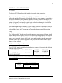
AST3225
Automatic
Transfer
Switch
Installation and User Manual for the
AST3225-2 Automatic Transfer Switch
Full Version
File: AST3225-2rev1.6.doc
May 9, 2003
2
READ MANUAL BEFORE INSTALLING UNIT
Receipt of shipment and warranty return information
Upon receipt of shipment, carefully remove the unit from the shipping container and
thoroughly examine the unit for shipping damage. In case of damage, immediately
contact the carrier and request that an inspection report be filed prior to contacting the
COMPANY.
All returned items must be shipped prepaid and include a return material authorization
(RMA) number issued by the COMPANY. RMA forms are available by contacting the
COMPANY.
Limited Warranty
The COMPANY (DynaGen Technologies Inc.) warrants the product with specifications
as explained herein. The COMPANY shall repair or replace any defective materials or
workmanship, f.o.b. the Company’s factory, which prove to be defective under normal
and proper use within three year’s from the date of shipment. This constitutes the only
warranty and no other warranty shall be implied.
For questions or comments regarding this product, contact:
DynaGen Technologies Inc.
Phone (902) 562 0133
Fax: (902) 567 0633
Email: [email protected]
WEB SITE: www.dynagensystems.com
Manual for AST3225 Automatic Transfer Switch
3
Table of Contents
1: GENERAL DESCRIPTION:
1:1 Switchgear
1:1:1 Specification
1:1:2 Operation
1:2 Relay Board Module
1:2:1 Sensing
Relay coil Sensing
Adjustable Voltage Sensing
1:2:2 System Operation
4
4
4
5
5
5
5
5
2: INSTALLATION INFORMATION:
2:1 General
2:2 Recommended Upstream Protection:
6
6
6
3: REPLACING PARTS
3:1 Parts List
3:2 Main Switch Removal and Replacement
3:3 Motor Removal and Replacement
3:4 Mechanical Limit Switch Adjustment
7
8
9
9
10
4: RECOMMENDED MAINTENANCE
11
5: DRAWINGS
5:1 Limit Switch Replacement
5:2 Mechanical Assembly
5:3 General Arrangement
5:4 Wiring Harness Connections
12
13
14
15
6: FIELD SET-UP:
6:1 Locking Mechanism (Optional)
6:2 Engine Exerciser
16
17
Manual for AST3225 Automatic Transfer Switch
4
1: GENERAL DESCRIPTION
1:1 Switchgear:
The AST3225 transfer switch mechanism consists of a basic mechanical switching
assembly that can be configured to satisfy various application requirements. (UL listed
E200939 Switch Mechanism). This manual describes the AST3225-2 model. (General
Arrangement page 14)
1:1:1 Specifications for AST3225-2 model
Normal/Emergency/Neutral Lug Connections 300
MCM MA Load connections 320 MCM (Max Wire
Size)
VOLTAGE
NORMAL
208/240
EMERGENCY
208/240
Amperage
225
225
Hz
60
60
Ph
Single
Single
Poles
2
2
Transfer Motor: 120V 60 HZ 2.3 amps thermally protected
Withstand/interrupting rating: symmetrical 10 KA. for loading at 100% of nameplate
current Enclosure: 24” wide x 30” high x 9” deep. NEMA 4.
1:1:2 Operation:
The AST3225 includes the suitable sensing circuitry for automatic transfer of an
electrical load to a stand-by power supply in the event of a drop or loss of voltage of any
or all phases of the normal power supply. Upon the restoration of the normal supply, the
electrical load is automatically re-transferred to the normal power supply.
The transfer motor utilizes power from the source to which the electrical load is being
transferred. The mechanism provides a positive mechanical interlock to prevent both
switches from being closed at the same time. The AST3225 also incorporates the basic
actuating motor control switches, terminal blocks, and voltage sensing connection points
for Utility Line sensing. Provision is also made for manual transfer of the power sources
if necessary. Instructions for the manual procedure are located on the operating arm of
the mechanism. The AST3225 mechanism is a lever-operated device controlled by a 120
volt unidirectional gear-motor.
The transfer motor drives a crank that in turn operates an aluminum lever arm, by sliding
a nylon slider between the top and bottom parts of the arm assembly. The lever, in turn,
operates the two switch handles by means of a unique spring and roller arrangement. The
travel position of the aluminum lever is detected by two micro switches, which in turn
disconnect power to the transfer motor, when appropriate.
Manual for AST3225 Automatic Transfer Switch
5
1:2 Relay Board Module:
The relay board provides means for automatic transfer of a utility source of power to an
emergency source of power, upon loss of the utility, and switches back again, upon
restoration of the utility. The relay board has no built in delays for transfer. Any required
delays must come from an external source (ie. engine controller, timer module).
1:2:1 Sensing:
The relay board module provides 2 types of voltage sensing:
i). Relay Coil Sensing:
When the slide switch, located on the relay module, adjacent to the 8 pin octal socket, is
in the ON or UP position, utility voltage sensing is provided by means of an on board
relay coil. The relay coil characteristics set the pick up and drop out of the main utility
source.
ii). Adjustable Voltage Sensing:
When the slide switch is in the OFF, or DOWN position, the on board relay coil is
bypassed, and voltage sensing is provide by a UL approved voltage sensing module,
which plugs into the 8 pin octal socket. The adjustable voltage monitor is a single setpoint voltage monitor. Input voltages 10% below the set-point range will cause the output
contacts to de-energize (unit is adjustable from (190-240 VAC). The adjustable drop out
relay recommended for use with the AST3225 Automatic Transfer Switch is the Symcom
201-200-SP-T Rev 5.20.
ADJUSTMENT PROCEDURE
Rotate the line voltage adjustment to the nominal line voltage feeding the transfer switch.
Measure the line to line voltage. If the voltage is up to 10% below the adjustable voltage
set point, and the LED on the monitor is illuminated, the adjustable voltage monitor is
working properly. The voltage sensor can also be factory set to customer specifications.
1:2:2 System Operation:
The relay board module has provisions for 12 and 24 VDC operation. The relay board
comes factory set for 12 VDC applications. Changing from 12 to 24 VDC will require
cutting the 2 jumper wires located next to the 5-position header.
Manual for AST3225 Automatic Transfer Switch
6
2: INSTALLATION INFORMATION
2:1 General
The basic AST3225 transfer switch includes all control wiring connections.
The electrical switchgear should be installed by a certified electrician, and all wiring
to/from the unit should agree with all applicable electrical codes, standards, and practices.
An engine controller or timing module (optional) is usually installed at the engine; this
installation can be performed by the electrician, or by a mechanic competent at engine
wiring. A diagram for wiring up a typical engine controller at the engine is included at
Section 5:4, Page 15
Interconnecting the engine controller or timer module controller to the transfer switch is
done simply with a 5-wire signal cable. We provide 50’ as a standard length with each
order, but any length, in 25’ increments can be provided upon request, for a nominal
charge.
The “cable assembly” has the transfer switch connector already mounted. Simply install
it in the Relay Board receptacle, pass the bare end through an appropriately located hole
in the enclosure, and run it to the engine controller or timer module. At the controller,
trim the wire to length, strip the color coded wires, and insert them into the appropriate
locations of the 5-pin connector supplied for the purpose. Then connect to the adaptor
harness. (Also supplied.)
2:2 Recommended Upstream Protection
The AST3225 Transfer Switch Mechanism has been approved for use with the following
upstream protective device:
MANUFACTURER
CLASSIFICATION
AMPERE
CATALOG
RATING
NUMBER
AMP-TRAP
CLASS J
300
A4J300
GOULD SHAWMUT
RECOMMENDED FUSE BLOCKS WITH BOX CONNECTORS FOR AMP-TRAP
CLASS J FUSES
FUSE
AMPERE
RATING
300
CATALOG NUMBER
600 VOLTS OR LESS
1 POLE
3 POLE
64031J
64033J
Manual for AST3225 Automatic Transfer Switch
7
3: REPLACING PARTS
The AST3225 transfer switch mechanism has been designed to allow all components to
be accessible and readily removable from the front of the back panel.
CAUTION When replacing any parts of the mechanism, isolate the transfer switch from
any possible source of power.
All AST3225 transfer switch mechanism hardware should be tightened sufficiently
before re-energizing the switch. The following table provides suggested tightening
torques.
Screw Size
#4
#6
#8
#10
1/4”
3/8”
Tightening Torque (in LB)
5
10
20
40
90
300
NOTE: For satisfactory performance, the switch terminal lugs must be securely fastened
to the terminal strips-90 (in-LB min.) Torque lugs screws to 200 (in-LB).
Replacement parts should be identified with reference to the Parts List on page 8 and the
Mechanical Assembly Drawing on page 13. All parts are available direct from the
factory. Be sure to state the model and serial number of the switch. These are located on
the arm label.
Manual for AST3225 Automatic Transfer Switch
8
3:1 REPLACEMENT PARTS LIST
PARTS DESCRIPTION
Washer #10 Flat
Bolt 3/8"-16x2" grade 5
Screw 6-32x1/2" machine binding head SS
Screw 6-32x3/8" machine pan head SS
Washer 3/8" flat 13/16"OD zinc plated
Nut 3/8"-16 hex SS
Screw 10-24x3" machine round head zinc plated
Washer #6 flat SS
Screw 4-40x 5/8 machine round head zinc plated Phillips
Flat Head Screw #6-32 x 1/2" Phillips zinc plated
Screw 8-32x5/16" machine binding head SS
Washer #8 spring lock SS
Screw 1/4"-20x1/2" set hex socket cup point SS
Spring pin 1/8"x1 3/8" coiled
5/16"-18 x 5/8" socket head cap screw
Screw 10-32x1/4" SOC HD set SS
Washer 5/16" spring lock
Washer #6 spring lock SS
Spacer 6-32 1 1/2" aluminum
Screw 1/4"-20x1" flat head
Washer 1/4" spring lock
Nut 1/4"-20 hex
Washer #10 spring lock zinc plated
Screw 10-24x5/8" pan head zinc plated
Screw 6-32x1/4" machine binding head SS
Switch
Gear Motor
Terminal Lug
Molded Case Switch
Terminal Lug
Actuating Arm Slider
Slider Pin
Actuating Arm Pivot Block
Spring Detail
Inner Roller Spacer
Ref.
No.
1
2
3
4
5
6
7
8
9
10
11
12
13
14
15
16
17
18
19
20
21
22
23
24
25
26
27
28
30
31
48
49
50
51
52
Manual for AST3225 Automatic Transfer Switch
PARTS DESCRIPTION
Outer Roller Spacer
Spring Roller
Relay Module Wire Harness
Engine Exerciser Wire Harness
Engine Controller Wire Harness
Engine Exerciser
Ground Strap
Label Package
Relay Module
Engine Exerciser Bracket
Screw 1/4" x3/4” hexagon head
Relay – 12VDC or 24 VDC
Adjustable Voltage Monitor
M-6 Metric Hexagon Nut
# 6 x ¼” Aluminum Spacer
6-32 Hexagon Nut
Washer Nylon Shoulder
Lever Arm Angle - Upper
Lever Arm Cover Plate
Slider Cover
Motor Support Bracket
Pivot Support Bracket
Neutral Block Insulator
Neutral Block Plate
Cable
Back Panel Detail
Enclosure Detail
Lever Arm Angle - Lower
Limit Switch Spacer
Limit switch cam
Aluminum Crank Block
Squeeze Release Latch
Screw #6-32 x1" Machine Binding Head
Nylon Spacer - #6x1/2"
Ref.
No.
53
54
55
56
57
58
59
60
61
62
63
64
65
66
67
69
72
73
74
76
77
78
80
81
82
83
84
85
86
87
88
92
94
95
9
3:2 MAIN SWITCH REMOVAL AND REPLACEMENT
To remove the main normal or emergency switches, first electrically isolate the
transfer switch from all power sources.
a) Disconnect all cables and wiring from the switch terminals.
b) Open the cover on the operating arm, remove the pin slider and close the
cover.
c) Remove the switch operating arm assembly by removing the four screws
securing the pivot bracket to the back panel and lift the arm assembly
complete with bracket from the back panel.
d) The individual switches can now be readily unfastened and removed from
the back panel.
Replacement is the reverse of the above procedure. Note when replacing
the arm assembly, ensure that the switches are set one “off” and one “on”
and that the rollers on the arm springs equally straddle the switch operating
levers. Tighten the pivot bracket screws equally to ensure controlled
deflections of the arm springs.
3:3 MOTOR REMOVAL AND REPLACEMENT
–
Electrically isolate the transfer switch from all power sources.
–
Note the wire connections to the 12 position terminal connector.
–
Cut the motor connection wires (white and black) approximately 3 inches
from the terminal block. Strip each wire ¾ of an inch, and attach the
corresponding leads from the new motor with wire connectors approved
for 18 gauge wire. Remove the arm assembly as previously described.
–
Remove four screws securing the motor bracket to the back panel.
–
Lift the assembly out of the transfer switch.
–
Remove the crank and cam assembly by loosening the set screw in the cam
arm.
–
Remove four screws securing the motor to the underside of the motor
bracket. The motor can now be removed.
Manual for AST3225 Automatic Transfer Switch
10
Replacement is the reverse of procedure 3.3. Note that the crank arm must be positioned
flush with the end of the motor shaft, and the set screw opposite the flat surface on the
shaft.
3:4 MECHANICAL LIMIT SWITCH ADJUSTMENT
The limit switches controlling the normal and emergency positions of the main
switches, have been factory set to a clearance of 0.020” between the face of the
switch and the limit switch cam, to ensure continued reliable operation. Should it
become necessary to adjust this gap, in the event of replacing a limit switch for
example, the following procedure is recommended (see diagram page 12):
a) Electrically isolate the transfer switch from all power sources. Loosen the
pivot screw and clamp screw to enable the limit switch to rotate about the
pivot screw.
b) Open the cover on the operating arm and remove the pin slider to allow the
limit switch cam to be rotated manually.
c) Insert a 0.020” feeler gauge between the face of the limit switch cam and
the operating plunger of the switch. Rotate the limit switch about the pivot
screw to establish the 0.020” clearance. Tighten the clamp screw and pivot
screw.
d) Rotate the limit switch cam by hand to check the switch operation and
readjust if necessary
e) Replace the pin slider and close the cover.
Manual for AST3225 Automatic Transfer Switch
11
4: RECOMMENDED MAINTENANCE
The AST3225 transfer switch assembly has been designed to require minimum attention
under all environmental conditions normally encountered. All sliding and bearing
surfaces are inherently self-lubricating due to the combination of materials used and
therefore should not be lubricated, thus preventing any accumulation of dust and grit at
these locations. The gear-motor is also lubricated for the life of the unit, and requires no
attention.
Periodically inspect all terminals (load, line and control), and all fasteners for tightness.
Test the transfer switch operation upon initial installation, in both the motor and manual
modes. Periodically check for freedom of movement of the mechanism, hidden dirt or
corrosion, and any excessive wear on the mechanical operating parts. Clean or replace
parts when necessary.
Do not attempt to remove the arm assembly by loosening the pivot screw and lock nut.
Instead, remove the four screws holding the pivot bracket in position and lift the
assembly clear. This will facilitate any adjustment of the pivot screw and lock nut that
may be required after extended service.
Manual for AST3225 Automatic Transfer Switch
12
5:1 LIMIT SWITCH ADJUSTMENT
Manual for AST3225 Automatic Transfer Switch
13
5:2 AST3225 MECHANICAL ASSEMBLY
Manual for AST3225 Automatic Transfer Switch
14
5:3 AST3225 GENERAL ARRANGEMENT
Manual for AST3225 Automatic Transfer Switch
15
5:4 Wiring Harness and Control Module Connections
Manual for AST3225 Automatic Transfer Switch
16
6: FIELD SET-UP
6:1 Locking Mechanism
The AST3225 enclosure can be equipped with an optional locking mechanism
(parts required: locking mechanism and locking mechanism gasket), which
allows the Transfer Switch to be securely locked, and eliminate any form of
tampering with the switch. The locking mechanism can mount on either one of
the quarter turn door latches. The mounting procedure is as follows:
1). Open the door of the enclosure.
2). On the back of the enclosure door, remove the Philips head screw, which
secures the quarter turn latch.
3). Remove the quarter turn latch.
4). From the front of the enclosure, remove the quarter turn insert, rubber
gasket, and flat washer.
5). Remove the lock nut located on the back of the enclosure door.
6). On the back of the enclosure door, gently tap the quarter turn latch housing
until it is free from the door. NOTE: carefully observe how the quarter turn
latch housing is inserted in the door, as it has to be put back in the door in
the exact same manner.
7). Remove the quarter turn latch housing and the quarter turn latch housing
rubber gasket.
8). Place the locking mechanism gasket over the hole in the enclosure door,
and the locking mechanism over the gasket (the hasp on the locking
mechanism would go closest to the edge of the enclosure).
9). Repeat steps 2 through 7 in their reverse order.
Manual for AST3225 Automatic Transfer Switch
17
6:2 Engine Exerciser:
Introduction
The functions of the exerciser time clock are shown in the diagram below. The time
clock has two slide switches with three positions: The switch in the upper right corner is a
SET SWITCH used to set the present time and day for your locality, run the program,
change an existing exercise cycle or start a new program. The MODE SWITCH located
in the upper left corner can start the generator manually, exercise the generator
automatically, or disable the exerciser function. The push buttons below the clock
display are used to program the exercise day, time and duration. The SKIP BUTTON is
used to ignore an "exercise" day. The RESET BUTTON initializes the time clock
erasing any previous program.
Manual for AST3225 Automatic Transfer Switch
18
Programming the Exerciser Time Clock
The mode switch slider is in the O or "disable" position when packaged at the factory.
The set switch is in the "run" position.
Use the following steps to program the exerciser time clock for a particular exercise
day, time, and duration:
1.
Move MODE SWITCH to "auto" and the SET SWITCH to "run".
2.
Press the RESET BUTTON using the tip of a pencil or pen. This operation will
produce a blinking display showing "00:0" for the time and an arrow under the day
7 (Sunday).
3.
Move the SET SWITCH slider to the left (clock icon) position so the present day
and time can be set. A default time AM 12:00 appears in the display with an
arrow under the day 7 or Sunday.
4.
Press the DAY button (1..7) repeatedly until the arrow points to the actual day of
the week.
5.
Press the HOUR button (h) repeatedly until the actual time of day is displayed,
such as AM 5:00 or PM 5:00.
6.
Press the MINUTE button (m) repeatedly until the minute of the present hour is
displayed, such as AM 5:30 or PM 5:30.
7.
Move the SET switch slider to the "run" position. The present time is displayed
with the clock colon ":" blinking in one-second intervals. The arrow appears
continuously under the present day.
8.
Move the SET switch slider to the "program" position (P in a circle). The default
time for starting an exercise is AM 12:00. The day arrow is absent. A small 1
appears to the right of the time with a lamp symbol above the 1. The 1 (or odd
number) indicates the start of an exercise or contact closure. The lamp symbol
indicates that the exerciser contacts are closed.
9.
Press the DAY button (d) repeatedly until an arrow appears under the desired
exercise day (Monday = 1) for starting the exercise.
10.
Press the HOUR button repeatedly until the desired time for beginning the
exercise is displayed, such as AM 5:00 or PM 5:00.
11.
Press the MINUTE button repeatedly until the minute of the hour for beginning
the exercise is displayed, such as AM 5:30 or PM 5:30.
Manual for AST3225 Automatic Transfer Switch
19
12.
Press the PROGRAM button once more to set the day and time for ending the
exercise. A default time AM 12:00 appears in the display. A small 2 appears to
the right of the time. The lamp symbol is absent. The 2 (or even number)
indicates the end of an exercise or open contacts. The absence of the lamp symbol
indicates when the exerciser contacts will open.
13.
Press the DAY button repeatedly until an arrow appears under the desired day for
terminating the exercise (Monday = 1) as in step 9.
14.
Press the MINUTE button repeatedly until the desired minute of the exercise
termination hour is displayed, such as AM 5:40 or PM 5:40.
15.
Move the slider on the SET switch to the "run" position. The exerciser time clock
is now programmed to start the emergency generator at the desired day, time and
for the desired duration.
NOTE: It is possible to program one to eight "on - off" cycles or transitions for the
following day combinations: One to eight "on-off" cycles any day of the week; One to
eight "on-off" cycles Monday to Friday inclusive; One to eight "on-off" cycles both
Friday and Saturday only; One to eight "on-off" cycles Monday to Saturday inclusive;
One to eight "on-off" cycles Monday to Sunday inclusive; All day combinations can have
any combination of "on -off " cycles. Normally the exerciser time clock will only
require one "on-off" cycle once per week. The programming steps given above describe
how to exercise the generator once a week. EXAMPLE: Suppose that the desirable day
and time for exercising the generator is Saturday at 5:00 AM. Move the slider of the SET
SWITCH to the right (P in circle) position. Press the DAY BUTTON (1..7) repeatedly until
the arrow appears under day 6. Press the HOUR BUTTON (h) followed by the MINUTE
BUTTON repeatedly until the desired time AM5: 30 are displayed. The generator is to be
shut down after exercising for 10 minutes. With the slider of the SET SWITCH still in the
right (P in circle) position press the PROGRAM BUTTON once. The display will show
a continuous default time of AM 12:00. The day arrow(s) disappears. The small 1 will
change to a 2 and the lamp symbol disappears. Press the DAY BUTTON (1..7) again
repeatedly until the day arrow appears under day 6. Press the HOUR BUTTON (h) followed
by the MINUTE BUTTON again repeatedly until the desired time AM5: 40 are displayed.
Return the SET SWITCH slider to the "run" position. The exerciser time clock is
programmed to start the generator at 5:30 AM on Saturday morning and run for 10
minutes then shut down at 5:40 AM of the same day Saturday. Following this procedure,
the generator can be exercised as frequently as desired.
Manual for AST3225 Automatic Transfer Switch