1
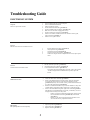
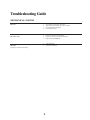
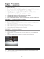
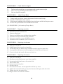
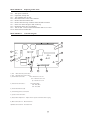
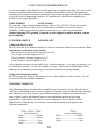
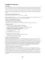
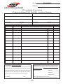
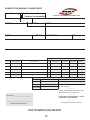
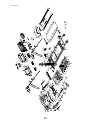
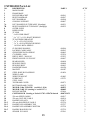
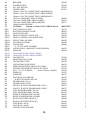
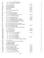
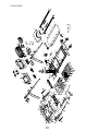
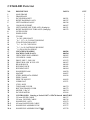
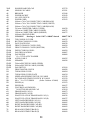
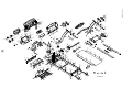
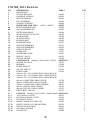
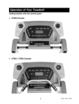
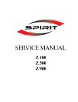
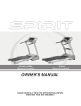
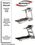
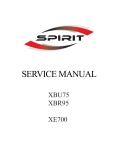
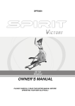
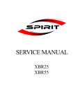
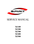
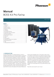
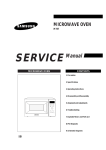
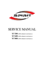
SERVICE MANUAL
XT 200 (With Alatech electronics)
XT 600 (With Alatech electronics)
XT 800 (With Alatech electronics)
Table of Contents
Troubleshooting Guide
Electronic System……………………………………………….3
Mechanical System……………………………………………...4
Repair Procedures
Procedure 1 (Calibrating the unit)………………………………5
Procedure 2 (Checking wire harness)…………………………...5
Procedure 3 (Speed sensor adjustment)…………………………5
Procedure 4 (Checking treadmill circuit breaker)………………5
Procedure 5 (Checking roller for magnet)………………………6
Procedure 6 (Adjust torque boost)………………………………6
Procedure 7 (Replacing controller)……………………………...6
Procedure 8 (Replacing wire harness)…………………………...6
Procedure 9 (Replacing drive motor)……………………………6
Procedure 10 (Replacing incline motor)…………………………7
Procedure 11 (Controller diagram)………………………………7
Procedure 12 (Wiring diagram)………………………………….8
Procedure 13 (Engineering mode)…………………………….....9
XT Series Warranty
Contacting Technical Service…………………………………....10
Treadmill Warranty……………………………………………...10
Warranty Policy………………………………………………….11
Parts Order Form………………………………………………...12
Warranty Labor Credit Form…………………………………….13
XT200
Exploded view……………………………………………............14
Parts list........................................................................................15 - 18
XT600
Exploded view…………………………………………………....19
Parts list........................................................................................20 - 23
XT800
Exploded view…………………………………………………....24
Parts list........................................................................................25 - 28
2
Troubleshooting Guide
ELECTRONIC SYSTEM
1.
2.
3.
4.
5.
6.
7.
8.
No power
There is no power to the console.
9.
Unit must be plugged into an outlet with power
Power switch must be illuminated
Tether cord must be in place
Check treadmill circuit breaker. (procedure 4)
Check “POWER” LED on controller. (procedure 11)
Make sure wires on board are plugged in securely.
Check wire harness for continuity. (procedure 2)
If LED’s on controller are not lit, test fuse on controller. If fuse is good,
replace controller. (procedure 7)
If LED’s are on, replace console.
LS error
Belt movement for a few seconds then LS error
1.
2.
3.
4.
5.
1.
2.
3.
LS error
No belt movement at all then LS error
1.
2.
3.
Incline does not work
4.
5.
1.
2.
3.
Belt surging
Belt speeds up and slows down frequently
3
Run the calibration procedure. (procedure 1)
Adjust speed sensor. (procedure 3)
Check roller for magnet (Procedure 5)
Check wire harness for continuity. (procedure 2)
If roller has a magnet and sensor adjustment does not fix, replace speed
sensor.
Run the calibration procedure. (procedure 1)
Check wire harness for continuity. (procedure 2)
Look at LED labeled “PWM”. (procedure 11)
-If it lights up when the START button is pressed, replace the controller.
- If it does not light when the START button is pressed, replace the
console.
Run the calibration procedure. (procedure 1)
Check wire harness for continuity. (procedure 2)
If there is an ERR message in the incline window, make sure that all the
wires from the incline motor are connected to the controller correctly
(procedure 12). If they are connected correctly, and the calibration does not
fix, replace the incline motor. (procedure 10)
When the UP and DOWN buttons are pressed, there should be a “beep” and
a number change in the incline window. If there isn’t, replace the console.
Observe the UP and DOWN diagnostic lights on the controller (procedure
11). When the UP or DOWN buttons are pressed, you should (1) see one of
the lights come on and (2) hear a relay click.
If there is no relay click and no diagnostic lights, replace console,
lower and middle wire harness (procedure 8), and controller
(procedure 7).
If there is a relay click and a diagnostic light and motor wires
are connected correctly, replaced incline motor
Adjust torque boost (procedure 6)
Adjust speed sensor (procedure 3)
Replace controller (procedure 7)
Troubleshooting Guide
MECHANICAL SYSTEM
Belt noise
Drive motor noise
Deck noise
Squeaking or creaking while walking
1.
2.
3.
4.
Check belt to see if it needs to be tracked.
Take off motor hood to make sure noise is from belt.
Check belt and deck for damage.
Clean deck and re-lube.
1.
2.
3.
Check wires around motor for rubbing.
Remove, clean, and re-insert the motor brushes
Replace motor. (procedure 9)
1.
2.
Tighten deck bolts
Clean and re-lube deck
4
Repair Procedures
PROCEDURE 1: Calibrating the unit
1.1
1.2
1.3
1.4
1.5
1.6
1.7
1.8
Remove tether cord.
Press and hold the START and FAST buttons. Replaced the tether cord while maintaining the
buttons. Display will show “FACTORY SETTING”. Press ENTER.
Units English / Metric. Press UP or DOWN to change. Press ENTER.
Adjust wheel diameter using UP or DOWN. Should be 2.810 for XT200 & XT600
3.060 for XT800. Press ENTER.
Adjust minimum speed to 0.5 using UP and DOWN. Press ENTER.
Adjust maximum speed to 12 using UP and DOWN. Press ENTER.
Adjust maximum elevation to 15 using UP and DOWN.
Press START to begin calibration. DO NOT STAND ON BELT DURING CALIBRATION.
PROCEDURE 2: Checking wire harness for continuity
2.1
2.2
2.3
2.4
2.5
Set your multimeter to read ohms.
Place the test leads at opposite ends of the wire, make sure both leads are on the same wire
and are in contact with metal.
If the reading is close to 0 ohms, the wire has continuity (unbroken).
If the reading is very high or there is no reading at all, there is no continuity.
If there is no continuity, the harness needs to be replaced.
PROCEDURE 3: Speed sensor adjustment
3.1
3.2
3.3
Take off the motor hood.
The speed sensor is located on the frame, near where the drive belt goes around the front
roller.
The sensor should be adjusted to about 1/16th of an inch from the front roller.
PROCEDURE 4:
4:1
4.2
Checking treadmill circuit breaker
The circuit breaker is a small, red button between the power cord and the power switch.
Press the button in to reset.
5
PROCEDURE 5:
5.1
5.2
5.3
The front roller should have a round magnet and a round counter weight.
Take a screw or something metallic and test each one.
Only one should be magnetic.
PROCEDURE 6:
6.1
6.2
6.3
6.4
Check roller for magnet
Adjust Torque Boost
Using a small screw driver, turn the dial counter clockwise until it stops.
Press the START button on the console.
With someone standing on the walking belt, turn clockwise until the belt begins to move.
Increase the speed and check for smooth belt movement.
(See PROCEDURE 11 for location of Torque Boost)
PROCEDURE 7:
7.1
7.2
7.3
7.4
7.5
7.6
Disconnect power cord from unit.
Remove motor hood.
Remove two Phillips screws holding in the controller.
Disconnect all wires connected to the controller.
Insert new controller, secure with Phillips screws.
Reconnect wires to controller. (See Procedure 12 )
PROCEDURE 8:
8.1
8.2
8.3
8.4
8.5
Replacing controller
Replacing wire harness
Turn power switch off.
Unplug harness from console and controller.
Tie the end of the new harness to the old harness (with a zip-tie or spare wire).
As you pull the old harness out of the upright, you will pull the new harness in.
Connect to board and console, & turn power back on.
PROCEDURE 9:
Replacing drive motor
9.1 Turn power switch off.
9.2 Disconnect red and black motor wires from controller.
9.3 Loosen tension bolt and remove four motor bolts.
9.4 Take off drive belt.
9.5 Insert new motor into place.
9.6 Put drive belt on.
9.7 Put in four motor bolts. Do not tighten them all the way down.
9.8 Tighten the tension bolt until you only have about an inch of play in the drive belt.
9.9 Tighten down the four motor bolts.
9.10 Plug the motor wires into the controller.
6
PROCEDURE 10:
10.1
10.2
10.3
10.4
10.5
10.6
10.7
10.8
10.9
10.10
Replacing incline motor
Turn power switch off.
If possible, fold up unit.
Turn treadmill onto its side.
Disconnect motor wires from controller.
Remove bolt from incline tube.
Remove bolt from top of incline motor and take out motor.
Insert new motor and put in bolt on the top.
Reconnect motor wires to controller.
Turn on unit. The new motor should turn until it is at “zero”.
Insert bolt into incline tube.
PROCEDURE 11:
Controller diagram
10
M+
JK 3
M-
AC 2
JK 5
8
SHUT DOWN
2
JK 6
JK 7
DOWN
COM
3
JK 3
TORQUE
AC 1
FUSE
1
9
MOT
DRV
POWER LIMIT
7
UP
PWM
SPEED
SENSOR
JK 3
Down
UP
JK 1
5
4
6
1) AC1 : White wire from power switch
2) AC2 : Black wire from power switch
3) Incline Motor Connection :
Down- Black wire to inc mtr.
Com- White wire to inc mtr.
Up- Red wire to inc mtr.
4) Transformer Connections :
JK5- Black,Black
JK6- Blue, Blue
JK7- Red, Red
5) Incline Potentiometer (VR)
6) Lower Wiring Harness Connection
7) Speed Sensor Connection
8) Torque Boost Adjustment - Adjust at lower speeds to eliminate motor surging
9) Motor Connection M- : Black motor wire
10) Motor Connection M+ : Red motor wire
7
JK 2
PROCEDURE 12:
Wiring diagram
Amp. Board
To Fan Assy.
JK 5
To Pulse Grip
JK 6
JK 3
JK 4
JK 1
JK 2
JK 5
JK 10
JK 9
To Tether Cord
JK 2
JK 5
JK 3
JK 2
Heart Rate Rec.
To Spd. Switch
To Inc. Switch
To Upright Harness
Transformer
Motor
BLUE
BLUE
BLACK
BLACK
RED
RED
M+
JK 3
M-
FUSE
AC 2
SHUT DOWN
JK 6
BLACK
WHITE
Incline
Motor
RED
DOWN
COM
JK 3
RED
BLACK
JK 5
TORQUE
AC 1
JK 7
MOT
DRV
POWER LIMIT
UP
PWM
SPEED
SENSOR
JK 3
Down
UP
JK 1
JK 2
Speed Sensor
Z 100-700
4-21-05
8
PROCEDURE 13:
Engineering mode
1. Remove the tether cord.
2. Press and hold the START, ENTER, and STOP buttons and replaced the tether
cord.
3. The display will say ENGINEERING MODE. Press ENTER.
4. Press the UP and DOWN buttons to scroll through the following sub menus:
-Calibration
-Factory Settings
-Security
-Functions
-Display Test
-Key Test
5. Press ENTER to access the desired program.
-Calibration
Speed Calibration – In this mode, you can test the speed.
Incline Calibration – In this mode, you can test the incline.
-Factory Settings
This mode will allow you to view the Wheel size, Max inc, Max and Min speed.
Use the UP and DOWN buttons to scroll through. (They cannot be changed here)
-Security
Child Lock On/Off
Press ENTER to turn on or off. To unlock display, press START and ENTER.
-Functions
Sleep Mode On/Off. Press ENTER to turn on or off.
Units English/Metric. Press ENTER to change.
Maintenance
Lube Message Reset. Press ENTER to reset.
Odometer Reset. Press ENTER to reset.
Pause Mode On/Off. Press ENTER to turn on or off.
-Display Test
Test all LED’s
-Key Test
Test all buttons on console.
9
CONTACTING CUSTOMER SERVICE
It is the responsibility of the Dealer to assemble and setup any Spirit product they have sold, as well
as diagnose problems and perform service, regardless of the product’s location. Recognizing the
importance of insuring the consumer’s satisfaction, Spirit technical support will always be available
to assist the Dealer in diagnosing a problem. All warranties are valid from the original date of
purchase by the original purchaser.
PARTS ORDERS
Fax 870-930-9013
Fax your order using a completed parts purchase order to (870) 930-9013. Please do not call to
place your parts orders, fax only. Service technicians are available to assist in the repair of
treadmills. If taking parts orders by telephone, customer service calls will go unanswered.
Standard shipping is UPS ground. If you need an order shipped by another method, you must
pay for shipping.
CUSTOMER SERVICE
Call 800-258-4555
Calling from Store Location
Dial 1 to reach the first available technician, or select the extension number for one technician. You
must have the serial number of the machine.
Eddie Greene, Customer Service Supervisor ext. 630
Jerry Savage, Customer Support ext. 632
Travis Lawrence, Customer Support ext. 633
Kevin Thomas, Customer Support ext. 628
If the technician you choose is unavailable, leave a detailed message. Leave only one message. Do
not call another extension. Do not leave multiple messages. This results in a duplication of effort
and keeps our technicians from assisting you and other customers in a prompt manner.
Calling from Customer Location
Dial 0 for an operator. Relay to the operator you are a dealer and in a customer’s home. You will
be assisted by the first available technician.
TREADMILL WARRANTY
Spirit Manufacturing Inc. warrants all its treadmills’ parts for a period of 5 years from the date of
retail sale, as determined by sale receipt, or eighteen (18) months from the original factory shipping
date, whichever comes first. Spirit’s responsibilities include providing new or remanufactured
parts, at Spirit’s option, and technical support to our independent dealers and servicing
organizations. In the absence of a dealer or service organization, these warranties will be
administered by Spirit directly to a consumer. An extended warranty period applies to the
following components:
XT200 - XT600 - XT800
(Home Warranty)
Frame———————Lifetime
Motor———————Lifetime
All Parts——————5 Years
Labor————-———2 Years
XT800
(Commercial Warranty)
Frame————————Lifetime
Parts—————————3 Years
Labor—————————1 Year
10
WARRANTY POLICY
Parts Returns
It is very important that you have not only the model number but also the serial number on hand when placing a parts
order. If a serial number is provided at the time a warranty parts order is placed the required parts will be sent to you
at no charge. If the unit is no longer covered under warranty the parts will be billed to you on 30 day payment terms.
If a warranty replacement part is required to be returned to Spirit it will be noted on the packing list included in your
shipment. Also noted on the packing list will be the amount you will be invoiced if the parts are not returned within
30 days.
Parts Required to be Returned for Credit
Upper and Lower Electronics - All STS / SC / SL / Inspire / Z / XT Series
Paperwork Requirement: A copy of your invoice or packing list and diagnostic form (if included with replacement
part) must be returned with the defective part to receive warranty consideration.
Warranty Labor Reimbursement Procedure
Complete Request for Warranty Labor Credit Form.
Fax completed form to Terry Jordan at (870) 930-9013.
Once Spirit has received your returned parts, your request will be processed and returned by fax to you.
What is Not Covered
1)
2)
3)
4)
5)
6)
7)
8)
Failures created due to improper installation or maintenance.
Repairs requiring only simple adjustments, fuses, or calibrations.
Damages sustained from shipping - Freight claim must be filed with your carrier.
Repairs that are made beyond the warranty period.
Repairs where the customer is paying the base labor fee to the dealer.
Units that are dealer stock or floor models.
Trips for diagnostic visit.
Residential units in a commercial setting.
Credit will not be issued for repairs in which:
1) Parts required for return are not returned to Spirit within 30 days.
2) All paperwork is not completed or returned.
3) Spirit confirms that work was not completed.
Warranty Labor Reimbursement Policy
Spirit has established a set of guidelines that are fair to both independent service companies and to Spirit. Our policy
on labor warranty reimbursement is simple...we pay a one time flat completion fee of $80 per service occurrence.
Once all work required to complete the repair has been finished and all parts required for return have been returned to
Spirit either credit or payment in the amount of $80 will be issued to your company. The one-time flat completion
fee of $80 will be paid only when the repair is complete and the unit has been returned to proper working condition.
If your company needs consideration for labor or trip fees that are higher than Spirit’s standard fees, they will be
evaluated on a case-by-case basis. (e.g. - travel to perform service work in Manhattan). Any change in the fee
schedule must be approved in writing by Spirit before any work is performed.
For Dealers That Wish To Use Third Party Service
It is Spirit’s policy that all dealers service products that they sell to end users. If your company chooses to use an
independent company for service, you are responsible for all service work. Our labor reimbursement policies apply in
every case and any charges in excess of Spirit’s one time flat completion fee will be billed back to the selling dealer.
In certain circumstances, we will work directly with an independent service company, but we will not pay for any
service that deviates from our policy for dealers wishing to have this arrangement. Dealers will be responsible to the
service company for all charges disallowed by Spirit. Any deviation from Spirit policy must be approved in advance
in writing.
11
Fax to:
870-930-9013
Attention:
PARTS PURCHASE ORDER
Fill in completely for processing.
All orders are shipped F.O.B. Spirit Mfg., Jonesboro, Arkansas.
Dealer Name
Account No.
Ship to
Street & No.
Street & No.
City
State
Phone Number
Fax Number
Purchase Order No. Dealer Buyer’s Name
Qty.
Zip
City
State
Phone Number
Fax Number
All parts ordered are considered stock orders unless a serial number is listed below each
parts’ description box. A serial number listed will qualify it for warranty evaluation.
Part No.
Description
Unit Price
Zip
Date of Order
Amount
Order Completion - Orders must be signed!
Shipping Instructions: (All orders will be shipped via ground delivery
If a part is not accompanied by a serial number, it will be assumed that the
unless otherwise indicated.) Buyer will be responsible for all expe-
part order is for stock. We encourage all dealers to stock parts. Spirit will
dited shipping charges.
always be fair to all dealers on credit for parts. Spirit reserves the right to
Special Instructions:
2nd Day Air________________
subject parts returns to a 20% restocking fee if Spirit determines that the
Next Day Air_______________
dealer has excessively ordered parts randomly to repair a problem.
Saturday Delivery___________
Buyer Signature_____________________________ Date____________
Initial Your Special Shipping Instructions Here______________________
(Orders for expedited shipping without initials will be shipped via ground delivery.)
12
REQUEST FOR WARRANTY LABOR CREDIT
Labor Warranty :
Date of Repair
Spirit is responsible
Customer is responsible
Model#
Service Company
P.O. BOX 2037 JONESBORO, ARKANSAS 72402
Serial Number
Svc CoAcct Number
Owner’s Name
Owner’s Address
Selling Dealer
Number
Selling Dlr Acct
Phone Number With Area Code
Date Sold
Problem
Repair Done
FACTORY USE ONLY
QUANTITY
PART NUMBER
PART DESCRIPTION
WTY
TEST RESULTS
UNIT PRICE
WORK ORDER
INVOICE
FACTORY USE ONLY
FREIGHT:
SHIPPING:
LABOR
TRIP
WARRANTY CREDIT WILL BE ISSUED TO
DEALER ACCOUNT.
____________
TOTAL LABOR
ALL PARTS MUST BE RETURNED TO FACTORY
UNLESS INSTRUCTED OTHERWISE.
____________
Authorization No.___________________________
CLAIMS MUST BE RETURNED TO SPIRIT
CORP. WITHIN 7 DAYS OF REPAIR.
____________
_________________________________________
SHADED AREAS FACTORY USE ONLY
WARRANTY ADMINISTRATOR
FAX TO SPIRIT (870) 930-9013
13
51
135
135
67
5
68
117
134 140
134
125
53
7B
93
57
25
122
119
122
137
117
139
122
119
119
40
117
124
39-5
14
126
126
84
29
29
44
75
39-4
39-3
6
124
137
34
58
86
90
115
89
101
106
58
50
1
110
58
58
117
115
126
29
117
75
58
86
4
110
117
126
76
35
87
123
52-12
119 52-21
52-17
130
119
123
119
123
117
130
52-13
39-5
117
115
42
127
128
52-2
119
113
105
117
39-3
119
119
52-16
130
39-4
130
139
43
41
20
105
113
93
122
130 130
52-14
52-16
119
117
62
122
119
122
119
52-15
52-15
52-14
52-15
38
29
110
117
117
78
58
45
36
46
78
110
117
125
47
118
134
117
52-23
134 140
133
26
7A
56
69
39-2
95
26
21
25
70
135
22
96
71
37
48
52-22
81
120
95
108
111
102
109
117
72
116
96
82
120
96
52-3
99
18
17
96
62 120
103
117
98
94
120
52-20
52-1
96
96
116
73
54
142
141
112
96
61
74
30
24
941005PM1038
96
117 117
55
120
23
79
80
61
112
117
112
117
XT200 / SPIRIT
# XT200-D81 Parts List
NO.
1
2
3
4
5
6
7A
7B
8
9
10
11
12
13
14
15
16
17
17
18
19
20
21
22
23
24
25
26
27
28
29
30
31
32
33
34
34
35
36
37
38
39
39~2
39~3
39~4
39~5
40
DESCRIPTION
MAIN FRAME
FRAME BASE
INCLINE BRACKET
RIGHT HANDRAIL
LEFT HANDRAIL
CONSOLE SUPPORT
LEFT HANDPULSE TUBE ASSY. (Handgrip)
RIGHT HANDPULSE TUBE ASSY. (Handgrip)
OUTER SLIDE
INNER SLIDE
2T LINK
˜ 8 x30L LINK SHAFT
˜ 8 x˜ 12.7 x 11.5L SHAFT BUSHING
2T FASTENING BRACKET
˜ 5 x˜ 8 x 25L CLEVIS PIN
˜ 5 x˜ 8 x 9L FASTENING BUSHING
˜ 1.0 DUAL ROTA-SPRING
CLENCHING HANDLE
LOCKING CABLE ASSY.
CHENCHING ROTA-SPRING
CYLINDER - 900N
DRIVE BELT - 240J/610J
FRONT ROLLER W/ PULLEY
REAR ROLLER
RUNNING DECK
RUNNING BELT
HANDGRIP FOAM
MAGNET
STEEL ROPE ROTA-SPRING
WIRE CLAMP
WIRE TIE MOUNT
LUBRICANT
STEEL ROPE
TOP FRAME COVER
BOTTOM FRAME COVER
MOTOR, 3.0hp TUR-YIH (serial #s 1-1116)
MOTOR, 3.0hp YC (starting w/ serial 1117+)
INCLINE MOTOR
CONTROLLER Starting w/ Serial # 1783 = 022670 Alatech
550 m/m SPEED CABLE
550 m/m INCLINE CABLE
HANDPULSE ASSY.
650 m/m HANDPULSE CABLE
HANDPULSE ASSEMBLY TOP
HANDPULSE ASSEMBLY BOTTOM
HANDLE BAR END CAP
SENSOR W/CABLE
15
PART #
000561
000547
000548
000897
000551
000552
000506
000563
000865
022554
022553
000497
000498
000488
000493
000550
000507
010026
010083
022271
000571
000572
000533
000602
022696
000479 DCI
000517
000516
022672
022756
022757
022758
022759
022561
O’TY
1
1
1
1
1
1
1
1
1
1
1
1
2
2
1
1
1
1
1
1
1
1
1
1
1
1
2
2
1
1
6
1
1
1
1
1
1
1
1
1
1
2
1
2
2
2
1
41
42
43
44
45
46
47
48
49
50
51
52
52~1
52~2
52~3
52~12
52~13
52~14
52~15
52~16
52~17
52~20
52~21
52~23
52~24
52~32
53
54
55
56
57
58
59
60
61
62
63
64
65
66
67
68
69
70
71
72
73
74
75
BREAKER
POWER SOCKET
ON / OFF SWITCH
POWER CORD
100mm x 764 x 764 CONNECTING CABLE(BLACK)
300mm x 764 x 764 CONNECTING CABLE (WHITE)
300mm x 764 x 764 CONNECTING CABLE(BLACK)
700 m/m COMPUTER CABLE (UPPER)
1200 m/m COMPUTER CABLE (LOWER)
1200 m/m COMPUTER CABLE (MIDDLE)
1000m/m GROUND WIRE
CONSOLE
Starting w/ Serial # 1783 = 000478 Alatech
TOP CONSOLE COVER
BOTTOM CONSOLE COVER
FACE PLATE LENS
FRONT CONSOLE COVER (TOP)
FRONT CONSOLE COVER (BOTTOM)
DEFLECTOR FAN GRILL
FAN GRILL ANCHOR
FAN MOTOR
˜ 12 x 5.5T PLASTIC WASHER
AUDIO CABLE - AMP INPUT JACK HARNESS
SPEAKER
700m/m RECEIVER CABLE (UPPER)
500m/m RECEIVER CABLE (LOWER)
FAN SWITCH
FRONT MOTOR COVER
TOP MOTOR COVER
TOP MOTOR COVER PLATE
SPEED ADJUSTMENT SWITCH W/CABLE
INCLINE ADJUSTMENT SWITCH W/CABLE
M8 x ˜ 30 x 35 CUSHION
(Softer Cushion - 030060)
WHEEL(A)
WHEEL(B)
FOOT RAIL (ALUMINUM)
˜ 38 BUTTON HEAD END CAP
FRAME BASE CAP (L)
FRAME BASE CAP (R)
PLASTIC PLATE OF FRAME BASE CAP (L)
PLASTIC PLATE OF FRAME BASE CAP (R)
LEFT HANDGRIP SIDE CAP (LL)
LEFT HANDGRIP SIDE CAP (LR)
RIGHT HANDGRIP SIDE CAP (RL)
RIGHT HANDGRIP SIDE CAP (RR)
REAR ADJUSTMENT BASE (L)
REAR ADJUSTMENT BASE (R)
FOOT RAIL CAP (L)
FOOT RAIL CAP (R)
MOTOR COVER ANCHOR
16
022448
022658
022476
022812
000520
000576
000575
000475 DCI
000535
000470
000528
000569
000570
000509
000807
000808
000565
000568
023099
000508
000504
000524
022558
022559
022482
022479
000127
000530
022024
000473
000474
000526
000527
000480
000465
000466
000483
000468
000469
000603
000604
022484
1
1
1
1
1
1
1
1
1
1
1
1
1
1
1
1
1
2
4
2
6
1
2
1
1
1
1
1
1
1
1
6
2
2
2
2
1
1
1
1
1
1
1
1
1
1
1
1
2
76
77
78
79
79A
80
81
82
83
84
85
86
87
88
89
90
91
92
93
94
95
96
97
98
99
100
101
102
103
104
105
106
107
108
109
110
111
112
113
114
115
116
117
118
119
120
122
123
˜ 10 x ˜ 24 x 3T NYLON WASHER (A)
˜ 50 x ˜ 13 x 3T NYLON WASHER (B)
˜ 30 x 3/8" FOOT PAD
NON-SLIP RUBBER(L)
NON-SLIP RUBBER
NON-SLIP RUBBER(R)
SAFETY KEY
BELT GUIDE
˜ 14 x˜ 10 x 35 WHEEL SLEEVE
SENSOR RACK
1/2" x 1-1/4" CARRIAGE BOLT
1/2" x 1" HEX HEAD SCREW
3/8" x 4-1/2" SOCKET HEAD CAP SCREW
3/8" x 3-3/4" HEX HEAD SCREW
3/8" x 1-1/2" HEX HEAD SCREW
3/8" x 1" HEX HEAD SCREW
3/8" x 2" THUMB HEAD SOCKET SCREW
5/16" x 1" BUTTON HEAD SOCKET SCREW
5/16" x 2-3/4" BUTTON HEAD SOCKET SCREW
M8 x 60m/m HEX HEAD SCREW
M8 x 80m/m SOCKET HEAD CAP SCREW
M8 x 30m/m FLAT HEAD COUNTERSINK SCREW
M3 x 10m/m TAPPING SCREW
M5 x 15m/m TAPPING SCREW
5/16" x 42 m/m BUTTON HEAD SOCKET SCREW
1/2" x 8T NYLON NUT
3/8" x 7T NYLON NUT
5/16" x 6T NYLON NUT
M8 x 8T NYLON NUT
˜ 35 x ˜ 5/16" x 1.5T FLAT WASHER
˜ 25 x ˜ 10 x 1.5T FLAT WASHER
˜ 19 x ˜ 10 x 1.5T FLAT WASHER
˜ 5 x ˜ 10 x 1.0T FLAT WASHER
˜ 5/16" x ˜ 18 x 1.5T FLAT WASHER
˜ 5 x ˜ 12 x 1.0T FLAT WASHER
˜ 6 x ˜ 23 x 13 x 5.5T x 3T NYLON DISHED WASHER
M5 NYLON NUT
˜ 6.5 x ˜ 25 x 1.5T x 2.5H CONCAVE WASHER
˜ 10 SPRING WASHER
M3 SPRING WASHER
M5 RAISED WASHER
4x12m/m SELF TAPPING SCREW
5x16m/m TAPPING SCREW
5x19m/m TAPPING SCREW
3.5x12m/m SELF TAPPING SCREW
5 x 16m/m TAPPING SCREW
˜ 4 x ˜ 14 x 1.0T FLAT WASHER
3.5x25mm SELF TAPPING SCREW
17
022713
000313
000314
022497
00595
023101
022989
000580
000062
000061
010119
022389
010115
023102
000080
030039
010099
000077
000070
010110
010125
010113
010150
000915
022847
2
4
2
1
4
1
1
2
2
1
2
2
1
1
1
4
2
2
4
1
2
8
1
1
1
4
4
3
1
2
4
4
2
1
1
4
1
4
4
1
5
4
59
1
16
11
6
3
124
125
126
127
128
129
130
131
132
133
134
135
137
138
139
140
141
142
144
145
3x10 m/m TAPPING SCREW
4x38m/m SELF TAPPING SCREW
3.5 x 16 m/m TAPPING SCREW
3 x 10 m/m SELF TAPPING SCREW
3/8" x 6.5T NUT (for Foot Pad)
M3 NUT
3.5 x 32m/m SELF TAPPING SCREW
M5 IRON PLATE NUT
2.3 x 6m/m SELF TAPPING SCREW
3x 8m/m SELF TAPPING SCREW
5/16" x 2" BUTTON HEAD SOCKET SCREW
3.5x40 m/m SELF TAPPING SCREW
5/16" x 1-1/2" BUTTON HEAD SOCKET SCREW
5/16" x 15m/m BUTTON HEAD SOCKET SCREW
˜ 8 x 23 x 1.5T FLAT WASHER
˜ 8 x 23 x 1.5T CURVED WASHER
COMBINATION M5 ALLEN WRENCH & SCREWDRIVER
M6 ALLEN WRENCH
3.5x 6m/m SELF TAPPING SCREW
˜8 RAISED WASHER
HEART RATE RECEIVER BOARD
PULSE GRIP BOARD (HANDPULSE)
CONSOLE STICKER
HARDWARE KIT
OVERLAY
DECAL (SIDE)
18
010115
000325
010115
010125
000914
010109
023015
000462
000064
022707
000074
000089
022973
000476
000945
000463
000558
000513
000510
4
2
6
2
3
1
10
6
43
6
4
6
2
8
4
4
1
1
2
4
1
1
1
1
1
2
51
135
135
67
5
68
117
134 140
134
125
53
7B
93
57
25
122
119
122
137
117
139
122
119
119
40
117
124
39-5
19
126
126
84
29
29
44
75
39-4
39-3
6
122
124
137
58
86
90
139
43
41
20
34
105
113
93
115
89
101
106
58
50
1
110
117
75
58
58
117
115
126
29
58
86
4
110
117
126
76
35
87
123
52-12
38
29
110
117
36
78
58
46
78
110
117
26
7A
56
69
39-2
125
47
118
45
117
52-23
134 140
134
133
117
119 52-21
52-17
130
119
123
119
123
117
130
52-13
117
115
42
127
128
52-2
119
39-5
119
113
105
117
39-3
119
39-4
130
130
52-16
52-15
52-14
52-15
130 130
52-14
52-16
119
117
62
122
119
122
119
52-15
95
26
21
25
70
135
22
96
71
37
48
52-22
120
95
108
117
72
116
96
82
120
96
52-3
99
18
17
96
111
102
109
103
117
98
94
81
62 120
120
52-20
52-1
96
96
116
73
54
142
141
112
96
61
74
30
24
941005PM1038
96
117 117
55
120
23
79
80
61
112
117
112
117
XT600/ SPIRIT
# XT600-D82 Parts List
NO.
1
2
3
4
5
6
7A
7B
8
9
10
11
12
13
14
15
16
17
17
18
19
20
21
22
23
24
25
26
27
28
29
30
31
32
33
34
35
36
37
38
39
39~2
39~3
39~4
DESCRIPTION
MAIN FRAME
FRAME BASE
INCLINE BRACKET
RIGHT HANDRAIL ASSY.
LEFT HANDRAIL ASSY.
CONSOLE SUPPORT
LEFT HANDPULSE TUBE ASSY. (Handgrip)
RIGHT HANDPULSE TUBE ASSY. (Handgrip)
OUTER SLIDE
INNER SLIDE
2T LINK
˜ 8 x30L LINK SHAFT
˜ 8 x˜ 12.7 x 11.5L SHAFT BUSHING
2T FASTENING BRACKET
˜ 5 x˜ 8 x 25L CLEVIS PIN
˜ 5 x˜ 8 x 9L FASTENING BUSHING
˜ 1.0 DUAL ROTA-SPRING
CLENCHING HANDLE
LOCKING CABLE ASSY.
CHENCHING ROTA-SPRING
CYLINDER - 1000N
DRIVE BELT - 240J/610J
FRONT ROLLER W/ PULLEY
REAR ROLLER
RUNNING DECK
RUNNING BELT
HANDGRIP FOAM
MAGNET
STEEL ROPE ROTA-SPRING
WIRE CLAMP
WIRE TIE MOUNT
LUBRICANT
STEEL ROPE
TOP FRAME COVER
BOTTOM FRAME COVER
MOTOR, 3.5hp YC
INCLINE MOTOR
CONTROLLER Starting w/ Serial # 1037 = 022670 Alatech
550 m/m SPEED CABLE
550 m/m INCLINE CABLE
HANDPULSE ASSY
650 m/m HANDPULSE CABLE
HANDPULSE ASSEMBLY TOP
HANDPULSE ASSEMBLY BOTTOM
20
PART #
000561
000547
000548
000897
000551
000552
O’TY
1
1
1
1
1
1
1
1
1
1
000506
000564
000865
023095
022553
000497
000498
000491
000494
000550
000507
010026
010083
022271
000574
000572
000534
022696
000479 DCI
000517
000516
022672
022756
022757
022758
1
1
2
2
1
1
1
1
1
1
1
1
1
1
1
1
2
2
1
1
6
1
1
1
1
1
1
1
1
1
2
1
2
2
39~5
40
41
42
43
44
45
46
47
48
49
50
51
52
52~1
52~2
52~3
52~12
52~13
52~14
52~15
52~16
52~17
52~20
52~21
52~23
52~24
52~32
53
54
55
56
57
58
59
60
61
62
63
64
65
66
67
68
69
70
71
72
HANDLE BAR END CAP
SENSOR W/CABLE
BREAKER
POWER SOCKET
ON / OFF SWITCH
POWER CORD
100mm x 764 x 764 CONNECTING CABLE(BLACK)
300mm x 764 x 764 CONNECTING CABLE (WHITE)
300mm x 764 x 764 CONNECTING CABLE(BLACK)
700 m/m COMPUTER CABLE (UPPER)
1200 m/m COMPUTER CABLE (LOWER)
1200 m/m COMPUTER CABLE (MIDDLE)
1000m/m GROUND WIRE
CONSOLE
Starting w/ Serial # 1037 = 000487 Alatech
TOP CONSOLE COVER
BOTTOM CONSOLE COVER
FACE PLATE LENS
FRONT CONSOLE COVER (TOP)
FRONT CONSOLE COVER (BOTTOM)
DEFLECTOR FAN GRILL
FAN GRILL ANCHOR
FAN MOTOR
˜ 12 x 5.5T PLASTIC WASHER
AUDIO CABLE
SPEAKER
700m/m RECEIVER CABLE (UPPER)
500m/m RECEIVER CABLE (LOWER)
FAN SWITCH
FRONT MOTOR COVER
TOP MOTOR COVER
TOP MOTOR COVER PLATE
SPEED ADJUSTMENT SWITCH W/CABLE
INCLINE ADJUSTMENT SWITCH W/CABLE
M8 x ˜ 30 x 35 CUSHION
(Softer Cushion - 030060)
WHEEL(A)
WHEEL(B)
FOOT RAIL (ALUMINUM)
˜ 38 BUTTON HEAD END CAP
FRAME BASE CAP (L)
FRAME BASE CAP (R)
PLASTIC PLATE OF FRAME BASE CAP (L)
PLASTIC PLATE OF FRAME BASE CAP (R)
LEFT HANDGRIP SIDE CAP (LL)
LEFT HANDGRIP SIDE CAP (LR)
RIGHT HANDGRIP SIDE CAP (RL)
RIGHT HANDGRIP SIDE CAP (RR)
REAR ADJUSTMENT BASE (L)
REAR ADJUSTMENT BASE (R)
21
022759
022561
022448
022658
022476
022812
000520
000576
000575
000477 DCI
000535
000470
000528
000569
000570
000509
000807
000808
000565
000568
023099
000508
000504
000524
022558
022559
022482
022479
000127
000530
022024
000473
000474
000526
000527
000480
000465
000466
000483
000468
000469
2
1
1
1
1
1
1
1
1
1
1
1
1
1
1
1
1
1
1
2
4
2
6
1
2
1
1
1
1
1
1
1
1
6
2
2
2
2
1
1
1
1
1
1
1
1
1
1
73
74
75
76
77
78
79
79A
80
81
82
83
84
85
86
87
88
89
90
91
92
93
94
95
96
97
98
99
100
101
102
103
104
105
106
107
108
109
110
111
112
113
114
115
116
117
118
FOOT RAIL CAP (L)
FOOT RAIL CAP (R)
MOTOR COVER ANCHOR
˜ 10 x ˜ 24 x 3T NYLON WASHER (A)
˜ 50 x ˜ 13 x 3T NYLON WASHER (B)
˜ 30 x 3/8" FOOT PAD
NON-SLIP RUBBER(L)
NON-SLIP RUBBER
NON-SLIP RUBBER(R)
SAFETY KEY
BELT GUIDE
˜ 14 x˜ 10 x 35 WHEEL SLEEVE
SENSOR RACK
1/2" x 1-1/4" CARRIAGE BOLT
1/2" x 1" HEX HEAD SCREW
3/8" x 4-1/2" SOCKET HEAD CAP SCREW
3/8" x 3-3/4" HEX HEAD SCREW
3/8" x 1-1/2" HEX HEAD SCREW
3/8" x 1" HEX HEAD SCREW
3/8" x 2" THUMB HEAD SOCKET SCREW
5/16" x 1" BUTTON HEAD SOCKET SCREW
5/16" x 2-3/4" BUTTON HEAD SOCKET SCREW
M8 x 60m/m HEX HEAD SCREW
M8 x 80m/m SOCKET HEAD CAP SCREW
M8 x 30m/m FLAT HEAD COUNTERSINK SCREW
M3 x 10m/m TAPPING SCREW
M5 x 15m/m TAPPING SCREW
5/16" x 42 m/m BUTTON HEAD SOCKET SCREW
1/2" x 8T NYLON NUT
3/8" x 7T NYLON NUT
5/16" x 6T NYLON NUT
M8 x 8T NYLON NUT
˜ 35 x ˜ 5/16" x 1.5T FLAT WASHER
˜ 25 x ˜ 10 x 1.5T FLAT WASHER
˜ 19 x ˜ 10 x 1.5T FLAT WASHER
˜ 5 x ˜ 10 x 1.0T FLAT WASHER
˜ 5/16" x ˜ 18 x 1.5T FLAT WASHER
˜ 5 x ˜ 12 x 1.0T FLAT WASHER
˜ 6 x ˜ 23 x 13 x 5.5T x 3T NYLON DISHED WASHER
M5 NYLON NUT
˜ 6.5 x ˜ 25 x 1.5T x 2.5H CONCAVE WASHER
˜ 10 SPRING WASHER
M3 SPRING WASHER
M5 RAISED WASHER
4x12m/m SELF TAPPING SCREW
5x16m/m TAPPING SCREW (Black)
5x19m/m TAPPING SCREW
22
000603
000604
022484
022713
000313
000314
022497
000595
023101
022989
000580
000062
000061
010119
022389
010115
023102
000080
030039
010099
000077
000070
010110
010125
1
1
2
2
4
2
1
4
1
1
2
2
1
2
2
1
1
1
4
2
2
4
1
2
8
1
1
1
4
4
3
1
2
4
4
2
1
1
4
1
4
4
1
5
4
59
1
119
120
122
123
124
125
126
127
128
129
130
131
132
133
134
135
137
138
139
140
141
142
144
145
3.5x12mm SELF TAPPING SCREW
5 x 16m/m TAPPING SCREW (Plated)
˜ 4 x ˜ 14 x 1.0T FLAT WASHER
3.5x25 m/m SELF TAPPING SCREW
3x10 m/m TAPPING SCREW
4x38m/m SELF TAPPING SCREW
3.5 x 16 m/m TAPPING SCREW
3 x 10 m/m SELF TAPPING SCREW
3/8" x 6.5T NUT (for Foot Pad)
M3 NUT
3.5 x 32m/m SELF TAPPING SCREW
M5 IRON PLATE NUT
2.3 x 6m/m SELF TAPPING SCREW
3x 8m/m SELF TAPPING SCREW
5/16" x 2" BUTTON HEAD SOCKET SCREW
3.5x40 m/m SELF TAPPING SCREW
5/16" x 1-1/2" BUTTON HEAD SOCKET SCREW
5/16" x 15m/m BUTTON HEAD SOCKET SCREW
˜ 8 x 23 x 1.5T FLAT WASHER
˜ 8 x 23 x 1.5T CURVED WASHER
COMBINATION M5 ALLEN WRENCH & SCREWDRIVER
M6 ALLEN WRENCH
3.5x 6m/m SELF TAPPING SCREW
˜ 8 RAISED WASHER
HEART RATE RECEIVER BOARD
PULSE GRIP BOARD (HANDPULSE)
CONSOLE STICKER
HARDWARE KIT
DECAL (SIDE)
OVERLAY
23
010113
010150
000915
022847
010115
000325
010115
010125
000914
010109
023015
000462
000064
022707
000074
000089
022973
000476
000945
000463
000567
000512
000513
16
11
6
3
4
2
6
2
3
1
10
6
43
6
4
6
2
8
4
4
1
1
2
4
1
1
1
1
1
XT800 / SPIRIT
107
37-1
101
37-21
31
34
50-1
107
52
37-18
37-20
37-18
37-15
37-14
37-15
37-15
89
80
37-16
37-14
90
37-16
90 90
80
90
89
89
80
89
49
89
97
37-13
92
94
50-2
92
74
50
119 50
50-3
37-17
104
115
93
110
104
110
116
24
87
82
82
84
87
32
51
26
98
21
43
87
87
44
78 73
44
78 73
56
87
83
2
59 75
73
59
56
75
15
72
13
57
12
72
43
87
83
43
64
87
87
83
91
43
88
87
88
91
98
70
60
59
44
47
71
57
73
59
78
87
83
43
65
44
67
78
72
72
1
76
56
16
87
83
68
87
87
71
42
30
58
47
84
42
22
65
87
83
43
96
28
29
72
17
87
46
92
78
23
76
87 100
84
19
87
96
17
24
27
66
82
95 25
96
17
69
72
118
36
115
9
10
118
84
87
92 40
77
87
93
7
87
86
117
20
50-3
119
87
46
92
84
87
87
117
85
79
85
79
92
84
45
14
6
37-19
92
41
92
49
63
50-2
87
92
92
89
97
114
102
8B
90
97
90
94
14
92
39
89
89
37-17
80
106
105
109
3
110
89
37-12
106
89 105
109
80
8A
102
102
89
80
89
37-22
101
35 50-1
38
48
107
81
81
37-3
110
4
37-20
55
54
53
37-2
98
60
18
111
112
62
11
56
70
87
941005PM1035
61
87
113
# XT 800_A82-1 Parts List
NO.
1
2
3
4
5
6
7
8A
8B
9
10
11
12
13
14
15
16
17
18
19
20
21
22
23
24
25
26
27
28
29
30
31
32
33
34
35
36
37
37~1
37~2
37~3
37~12
37~13
37~14
37~15
37~16
DESCRIPTION
MAIN FRAME
INCLINE BRACKET
HANDRAIL SUPPORT
RIGHT HANDRAIL
LEFT HANDRAIL
CONSOLE SUPPORT
HANDPULSE TUBE ONLY (ASSY. = 000923)
RIGHT HANDGRIP ASSY.
LEFT HANDGRIP ASSY.
DECK CROSS BRACE
FRONT ROLLER W/ PULLEY
REAR ROLLER
RUNNING DECK
RUNNING BELT
HANDGRIP FOAM
NON-SLIP RUBBER(L)
NON-SLIP RUBBER(R)
WIRE TIE MOUNT
LUBRICANT
TOP FRAME COVER
MOTOR, 3.5hp YC
INCLINE MOTOR
CONTROLLER Starting w/ Serial #1003 = 022282
SENSOR W/CABLE
BREAKER
POWER SOCKET
ON / OFF SWITCH
POWER CORD
100mm x 764 x 764_CONNECTING CABLE (BLACK)
150mm x 764 x 764_CONNECTING CABLE (WHITE)
150mm x 764 x 764_CONNECTING CABLE (BLACK)
800 m/m_COMPUTER CABLE (UPPER)
800m/m_COMPUTER CABLE (LOWER)
1200 m/m_COMPUTER CABLE (MIDDLE)
800 m/m_SPEED CABLE (UPPER)
800 m/m_INCLINE CABLE (UPPER)
DRIVE BELT, 240J/610J
CONSOLE Starting w/ Serial # 1003 = 000442 Alatach
TOP CONSOLE COVER
BOTTOM CONSOLE COVER
FACE PALTE LEANS
FRONT CONSOLE COVER (TOP)
FRONT CONSOLE COVER (BOTTOM)
DEFLECTOR FAN GRILL
FAN GRILL ANCHOR
FAN MOTOR
25
PART #
000562
000556
000486
000485
000898
000472
000890
000891
000460
000499
000500
000492
000495
000553
000313
000314
010083
022271
000573
000534
022696
000479 DCI
022561
022448
022658
022476
022812
022720
000503
000575
022754
022755
022553
000471 DCI
000535
000470
000529
000569
000570
000509
000807
000808
O’TY
1
1
1
1
1
1
1
1
1
1
1
1
1
1
2
1
1
5
1
1
1
1
1
1
1
1
1
1
1
1
1
1
1
1
1
1
1
1
1
1
1
1
1
2
4
2
37~17
37~18
37~19
37~20
37-21
37~30
38
39
40
41
42
43
44
45
46
47
48
49
50
50~1
50~2
50~3
51
52
53
54
55
56
58
59
60
61
62
63
64
65
66
67
68
69
70
71
72
73
74
75
76
77
ROUND END CAP
PLASTIC WASHER
AUDIO CABLE
SPEAKER
HEART RATE RECEIVER CABLE
FAN SWITCH
SPEED ADJUSTMENT SWITCH W/CABLE
INCLINE ADJUSTMENT SWITCH W/CABLE
MOTOR BASE CAP (L)
MOTOR BASE CAP (R)
MAGNET
M8 x ˜ 30 x 35 CUSHION (Softer Cushion - 030060)
˜ 81 x35_WHEEL
TOP MOTOR COVER
MOTOR COVER ANCHOR
FOOT RAIL
BEVERAGE HOLDER
˜ 38 BUTTON HEAD END CAP
HANDPULSE W/CABLE ASSY.
700 m/m HANDPULSE CABLE
HANDPULSE ASSEMBLY TOP
HANDPULSE ASSEMBLY BOTTOM
FRAME FRONT COVER
LEFT HANDGRIP SIDE CAP (LL)
LEFT HANDGRIP SIDE CAP (LR)
RIGHT HANDGRIP SIDE CAP (RL)
RIGHT HANDGRIP SIDE CAP (RR)
%25x50_SQUARE END CAP
˜ 24 x ˜ 10 x 3T _NYLON WASHER (A)
˜ 50 x ˜ 13 x 3T_NYLON WASHER (B)
˜ 38 x 3/8"_FOOT PAD
REAR ADJUSTMENT BASE (L)
REAR ADJUSTMENT BASE (R)
SAFETY KEY
BELT GUIDE
1/2" x 57m/m_HEX HEAD SCREW
3/8" x 4-1/2"_SOCKET HEAD CAP SCREW
3/8" x 4"_ SOCKET HEAD CAP SCREW
3/8" x 1-3/4" _HEX HEAD SCREW
M8 x 60m/m _HEX HEAD SCREW
M8 x 80m/m _ SOCKET HEAD CAP SCREW
M8 x 50m/m_FLAT HEAD COUNTERSINK SCREW
M8 x 30m/m_FLAT HEAD COUNTERSINK SCREW
3/8" x 3/4"_BUTTON HEAD SOCKET SCREW
3/8" x 1"_HEX HEAD SCREW
1/2" x 15T_NYLON NUT
3/8" x 7T_NYLON NUT
M8_NYLON NUT
26
000515
000565
022946
000484
023099
022558
022559
000544
000545
000507
022482
023016
000505
000922
000532
000455
022024
000518
023212
000519
000480
000481
000482
000483
000630
000549
000522
000521
022497
000595
000580
020349
022999
000061
000080
2
6
1
2
1
1
1
1
1
2
6
4
1
2
2
1
2
2
1
2
2
1
1
1
1
1
4
2
4
2
1
1
1
2
2
1
1
1
1
2
2
6
4
4
2
2
1
78
79
80
81
82
83
84
85
86
87
88
89
90
91
92
93
94
95
96
97
98
99
100
101
102
103
104
105
106
107
108
109
110
111
112
113
114
115
116
117
118
119
120
121
122
123
124
125
˜ 19 x ˜ 10 x 1.5T_ FLAT WASHER
˜ 25 x ˜ 10 x 1.5T _ FLAT WASHER
˜ 4 x ˜ 14 x 1T _ FLAT WASHER
3x8 m/m_SELF TAPPING SCREW
M5_RAISED WASHER
˜ 5 x 25 x 1.5T x5.8H_CONCAVE WASHER
M5_IRON PLATE NUT
˜ 10 x1.5T_SPRING WASHER
5 x19 m/m_ TAPPING SCREW
5 x16 m/m_ TAPPING SCREW
4x12 m/m_SELF TAPPING SCREW
3.5x12 m/m_SELF TAPPING SCREW
3.5x32 m/m_SELF TAPPING SCREW
˜ 6.5 x ˜ 25 x 1.5T x 2.5H_CONCAVE WASHER
5x16 m/m_ TAPPING SCREW
3x20 m/m_ TAPPING SCREW
4x38 m/m_SELF TAPPING SCREW
3x10 m/m_SELF TAPPING SCREW
3.5 x16m/m_ TAPPING SCREW
3.5 x25m/m_SELF TAPPING SCREW
3/8"_ NUT
2.3x6 m/m_SELF TAPPING SCREW
SENSOR RACK
5/16" x 2"_BUTTON HEAD SOCKET SCREW
5/16" x 15m/m_BUTTON HEAD SOCKET SCREW
3/8" x 2"_BUTTON HEAD SOCKET SCREW
5/16" x 1-3/4"_BUTTON HEAD SOCKET SCREW
5/16" x 2-3/4"_HEX HEAD SCREW
5/16" x 1-1/2"_BUTTON HEAD SOCKET SCREW
3.5 x 40m/m_SELF TAPPING SCREW
3/8" x 2T_SPRING WASHER
˜ 8 x ˜ 23 x 1.5T_SPRING WASHER
˜ 8 x ˜ 23 x 1.5T _CURVED WASHER
COMBINATION M5 ALLEN WRENCH & SCREWDRIVER
M6_ALLEN WRENCH
12m/m_ WRENCH
˜ 1" x 440 m/m x 5T_ FOAM(A)
˜ 1" x 360 m/m x 5T_ FOAM(B)
MOTOR FAN
M4 x 35m/m_TAPPING SCREW
M4 x 5T_NYLON NUT
˜ 1"_ ROUND END CAP
˜ 5 x ˜ 10 x 1T_FLAT WASHER
˜ 8_RAISED WASHER
˜ 10_RAISED WASHER
010109
030057
010110
000070
010113
000914
010150
000325
023082
022979
022847
023105
022989
010092
022707
023090
000086
000064
000462
000053
000089
022973
000342
000876
250m/m_ BLACK CONNECTING CABLE OF MOTOR FAN
250m/m_ WHITE CONNECTING CABLE OF MOTOR FAN
CONNECTING CABLE OF MOTOR
27
000637
000638
6
4
6
6
4
6
6
4
1
35
4
16
10
2
11
4
2
2
5
3
3
43
1
4
10
2
4
2
2
6
2
4
8
1
1
1
1
2
1
2
2
2
6
2
2
1
1
1
126
BOLT ACCESS CAP
HEART RATE RECEIVER BOARD
PULSE GRIP BOARD (HANDPULSE)
CONSOLE STICKER
HARDWARE KIT
OVERLAY
DECAL (SIDE)
28
000476
000945
000463
000451
000513
000514
2
1
1
1
1
1
2