1
MOTOROLA
FREEWARE
32-BIT CROSS ASSEMBLER
USER'S MANUAL
(UPDATED FOR VERSION 1.2)
BY SCOTT HOWARD
FIELD APPLICATIONS ENGINEER
MOTOROLA SEMICONDUCTOR PRODUCTS, CANADA
ADAPTED FROM KEVIN ANDERSON'S ORIGINAL 8-BIT TEXT
TABLE OF CONTENTS
CHAPTER 1.........................................................
1.1
1.2
1.3
1.4
4
INTRODUCTION ..........................................
ASSEMBLY LANGUAGE .....................................
OPERATING ENVIRONMENT .................................
ASSEMBLER PROCESSING ..................................
4
4
5
5
CHAPTER 2 ........................................................
6
2.1
2.2
2.3
INTRODUCTION ..........................................
SOURCE STATEMENT FORMAT ...............................
2.2.1
Label Field ....................................
2.2.2
Operation Field ................................
2.2.3
Operand Field ..................................
2.2.3.1 Expressions ..............................
2.2.3.2 Operators ................................
2.2.3.3 Symbols ..................................
2.2.3.4 Constants ................................
2.2.4
Comment Field ..................................
ASSEMBLER OUTPUT ......................................
CHAPTER 3 - RUNNING THE ASSEMBLER ................................
3.1
3.2
6
6
7
7
7
8
8
8
8
9
9
11
ASSEMBLER INVOCATION ..................................
ERROR MESSAGES ........................................
11
12
CHAPTER 4 - ASSEMBLER DIRECTIVES .................................
13
4.1
4.2
4.3
4.4
4.5
4.6
4.7
4.8
INTRODUCTION ..........................................
DC - DEFINE CONSTANT DATA .............................
DS - DEFINE STORAGE ...................................
EVEN - ALIGN TO EVEN WORD BOUNDARY ....................
EQU - EQUATE SYMBOL TO A VALUE ........................
OPT - ASSEMBLER OUTPUT OPTIONS ........................
ORG - SET PROGRAM COUNTER TO ORIGIN ...................
SECTION - SWITCH TO NEW PROGRAM SECTION ...............
13
13
14
14
14
14
15
15
APPENDIX A - CHARACTER SET .......................................
16
APPENDIX B - ADDRESSING MODES ....................................
18
B.1
B.2
B.3
B.4
B.5
B.6
B.7
B.8
DATA REGISTER DIRECT ..................................
ADDRESS REGISTER DIRECT ...............................
ADDRESS REGISTER INDIRECT .............................
ARI WITH POST INCREMENT ...............................
ARI WITH PRE DECREMENT ................................
ARI WITH DISPLACEMENT .................................
ARI WITH INDEX (8 BIT DISPLACEMENT) ...................
ARI WITH INDEX (BASE DISPLACEMENT) ....................
18
18
18
19
19
19
19
19
APPENDIX C - DIRECTIVE SUMMARY ..................................
APPENDIX D - ASSEMBLER LISTING FORMAT ...........................
21
22
APPENDIX E - S-RECORD INFORMATION ................................
E.1
E.2
E.3
E.4
23
INTRODUCTION ..........................................
S-RECORD CONTENT ......................................
S-RECORD TYPES ........................................
S-RECORD EXAMPLE ......................................
23
23
23
24
APPENDIX F - SYMBOL FILE INFORMATION .............................
26
F.1
F.2
F.3
F.4
INTRODUCTION ..........................................
SYMBOL FILE FORMAT ....................................
EXAMPLE ...............................................
DEBUGGING PROGRAMS WITH DB32 ..........................
26
26
26
27
APPENDIX G - SOFTWARE RELEASE NOTES ..............................
28
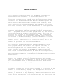
CHAPTER 1
GENERAL INFORMATION
1.1
INTRODUCTION
This is the user's reference manual for the IBM-PC hosted Motorola
Freeware 68332 cross assembler. It details the features and
capabilities of the cross assembler, assembler syntax and directives,
options, and listings. It is intended as a detailed reference and an
introduction for those unfamiliar with Motorola assembler syntax and
format. Those experienced with Motorola assembler products may wish to
examine the file AS32.DOC available with the cross assembler, which
briefly describes the differences between this assembler and earlier,
non-pc based versions. Also it would be advisable to check appendix F
for information on the features of the latest version of this program.
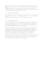
Assemblers are programs that process assembly language source program
statements and translate them into executable machine language object
files. A programmer writes his source program using any text editor or
word processor that can produce an ASCII text output. With some word
processors this is known as "non document" mode. Non document mode
produces a file without the non-printable embedded control characters
that are used in document formating. (Caution: assembling a file that
has been formatted with embedded control characters may produce
assembler errors. The solution is to convert the source file to pure
ASCII text.) Once the source code is written, the source file is
assembled by processing the file via the assembler.
Cross assemblers (such as the Motorola Freeware Assemblers) allow
source programs written and edited on one computer (the host) to
generate executable code for another computer (the target). The
executable object file can then be downloaded and run on the target
system. In this case the host is an IBM-PC or compatible and the
target system is based on the Motorola MC 68332 32-bit microprocessor,
such as the Motorola Business Card Computer (BCC). Motorola also
supplies Freeware Assemblers for all Motorola 8-bit Microcontrollers and
microprocessors.
The assembler is the executable program AS32.EXE. The details of
executing the assembler program is found in Chapter 3. The assembly
format for the source code is identical to that of Motorola's commercial
macro cross assembler which is available for Motorola VME 1131 Unix
systems and MS-DOS/PC-DOS operating systems.
1.2
ASSEMBLY LANGUAGE
The symbolic language used to code source programs to be processed by the
Assembler is called assembly language. The language is a collection of
mnemonic symbols representing: operations (i.e., machine instruction
mnemonics or directives to the assembler), symbolic names,operators, and
special symbols. The assembly language provides mnemonic operation codes
for all machine instructions in the instruction set. The instructions are
defined and explained in the Programming Reference Manuals for the
MC68332, available from Motorola under publication number CPU32RM/AD.
The
assembly language also contains mnemonic directives which specify
auxiliary actions to be performed by the Assembler. These directives are
not always translated into machine language.
1.3
OPERATING ENVIRONMENT
This assembler will run on any IBM-PC, XT, AT, PS-2, or true compatible.
The assembler may be run from a floppy disk drive or it may be copied
onto
a hard drive for execution. DOS 2.0 or later is required.
1.4
ASSEMBLER PROCESSING
The Macro Assembler is a two-pass assembler. During the first pass,
the source program is read to develop the symbol table. During the
second pass, the object file is created (assembled) with reference to
the table developed in pass one. It is during the second pass that
the source program listing is also produced.
Each source statement is processed completely before the next source
statement is read. As each statement is processed, the Assembler
examines the label, operation code, and operand fields. The operation
code table is scanned for a match with a known opcode. During the
processing of a standard operation code mnemonic, the standard
machine code is inserted into the object file. If an Assembler
directive is being processed, the proper action is taken.
Any errors that are detected by the Assembler are displayed before the
actual line containing the error is printed. If no source listing is
being produced, error messages are still displayed to indicate that
the assembly process did not proceed normally.
CHAPTER 2
CODING ASSEMBLY LANGUAGE PROGRAMS
2.1
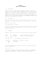
INTRODUCTION
Programs written in assembly language consist of a sequence of source
statements. Each source statement consists of a sequence of ASCII
characters ending with a carriage return. Appendix A contains a list
of the supported character set.
2.2
SOURCE
STATEMENT FORMAT
Each source statement may include up to four fields: a label (or "*"
for a comment line), an operation (instruction mneumonic or assembler
directive), an operand, and a comment.
2.2.1
Label Field
The label field occurs as the first field of a source statement. The
label field can take one of the following forms:
1. An asterisk (*) as the first character in the label field indicates
that the rest of the source statement is a comment. Comments are
ignored by the Assembler, and are printed on the source listing only
for the programmer's information.
2. A whitespace character (blank or tab) as the first character
indicates that the label field is empty. The line has no label and is
not a comment.
3. A symbol character as the first character indicates that the line
has a label. Symbol characters are the upper or lower case letters az, digits 0-9, and the special characters, period (.), dollar sign
($), and underscore (_). Symbols consist of one to 15 characters, the
first of which must be alphabetic or the special characters period (.)
or underscore (_). All characters are significant and upper and lower
case letters are distinct.
A symbol may occur only once in the label field. If a symbol does
occur more than once in a label field, then each reference to that
symbol will be flagged with an error.
With the exception of some directives, a label is assigned the value
of the program counter of the first byte of the instruction or data
being assembled. The value assigned to the label is absolute.
Labels may optionally be ended with a colon (:). If the colon is
used it is not part of the label but merely acts to set the label off
from the rest of the source line. Thus the following code fragments
are equivalent:
here: move.b
bne
here
move.b
bne
23,d0
here
23,d0
here
A label may appear on a line by itself. The assembler interprets this
as set the value of the label equal to the current value of the
program counter.
The symbol table has room for at least 2000 symbols of length 8
characters or less. Additional characters up to 15 are permissible at
the expense of decreasing the maximum number of symbols possible in
the table.
2.2.2
Operation Field
The operation field occurs after the label field, and must be preceded
by at least one whitespace character. The operation field must contain
a legal opcode mneumonic or an assembler directive. Upper case
characters in this field are converted to lower case before being
checked as a legal mneumonic. Thus 'nop', 'NOP', and 'NoP' are
recognized as the same mneumonic. Entries in the operation field may
be one of two types:
Opcode. These correspond directly to the machine instructions, as
defined by the MC68332 CPU reference manual.
Directive. These are special operation codes known to the Assembler
which control the assembly process rather than being translated into
machine instructions.
2.2.3
Operand Field
The operand field's interpretation is dependent on the contents of the
operation field. The operand field, if required, must follow the
operation field, and must be preceded by at least one whitespace
character. The operand field may contain a symbol, an expression, or a
combination of symbols and expressions separated by commas.
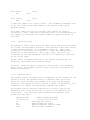
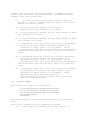
The operand field of machine instructions is used to specify the
addressing mode of the instruction, as well as the operand of the
instruction.
The following tables summarize the operand field
formats for the 68332.
Operand Format
==============
Dn
An
(An)
(An)+
M68332 Addressing Mode
======================
Data Register Direct
Address Register Direct
Address Register Indirect (ARI)
ARI with Post Increment
-(An)
ARI with Pre Decrement
(d16,An)
ARI with Displacement
(d8,An,Xn.Size*Scale)
ARI with Index (8 bit Displacement)
(bd,An,Xn.Size*Scale) ARI with Index (Base Displacement)
Dn
An
Xn
d8
d16
bd
Size
Scale
-
2.2.3.1
Any Data Register D0 to D7
Any Address Register A0 to A7
Any Address or Data Register
8 bit Displacement
16 bit displacement
32 bit displacement
a size specifier - may be W (Word, 16 bit) or L (Long, 32 bit)
an data object size specifier - may be 1, 2, 4, or 8
Expressions.
Expressions may consist of symbols, constants, parentheses, or the
character '*' (denoting the current value of the program counter) joined
together by one of the operators: + - * / % & | ^ ~ .
2.2.3.2
Operators.
The operators are the same as in the c programming language:
+
*
/
%
&
|
^
~
add
subtract
multiply
divide
remainder after division
bitwise and
bitwise or
bitwise exclusive or
bitwise not
Expressions are evaluated left to right. There is no precedence
inherent in any operator, but parentheses may be used to alter normal
operator processing. Arithmetic is carried out in signed twocomplement long precision (that's 32 bits on the IBM PC).
2.2.3.3 Symbols. Each symbol is associated with a 32-bit integer value
which is used in place of the symbol during the expression evaluation.
The asterisk (*) used in an expression as a symbol represents the
current value of the location counter (the first byte of a multi-byte
instruction).
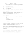
2.2.3.4 Constants. Constants represent quantities of data that do not
vary in value during the execution of a program. Constants may be
presented to the assembler in one of five formats: decimal,
hexadecimal, binary, or octal, or ASCII. The programmer indicates the
number format to the assembler with the following prefixes:
$
%
@
HEX
BINARY
OCTAL
An ASCII constant must be surrounded by single quotes (for example, the
letter 'A'). Unprefixed constants are interpreted as decimal. The
assembler converts all constants to binary machine code and are
displayed in the assembly listing as hex.
A decimal constant consists of a string of numeric digits. The value
of a decimal constant must fall in the range -2147483648 to 4294967295,
inclusive. The following example shows both valid and invalid decimal
constants:
VALID
----12345
INVALID
------12.3
REASON INVALID
-------------invalid character
A hexadecimal constant consists of a maximum of four characters from
the set of digits (0-9) and the upper case alphabetic letters (A-F),
and is preceded by a dollar sign ($). Hexadecimal constants must be
in the range $0 to $FFFFFFFF. The following example shows both valid and
invalid hexadecimal constants:
VALID
----$12
$ABCD
$001F
INVALID
------ABCD
$G2A
$FE432F018
REASON INVALID
-------------no preceding "$"
invalid character
too many digits
A binary constant consists of a maximum of 32 ones or zeros preceded by
a percent sign (%). The following example shows both valid and invalid
binary constants:
VALID
----%00101
%10100
INVALID
------1010101
%210101
REASON INVALID
-------------missing percent
invalid digit
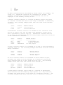
An octal constant consists of a maximum of eleven numeric digits,
excluding the digits 8 and 9, preceded by a commercial at-sign (@).
Octal constants must be in the ranges @0 to @177777. The following
example shows both valid and invalid octal constan ts:
VALID
----@377
@177600
INVALID
------@277272
@23914
REASON INVALID
-------------out of range
invalid character
A single ASCII character can be used as a constant in expressions.
ASCII constants are surrounded by single quotes (''). Any character,
including the single quote, can be used as a character constant.
The
following example shows both valid and inval id character constants:
VALID INVALID
----- ------'*'
'VALID'
REASON INVALID
-------------too long
For the invalid case above the assembler will not indicate an error.
Rather it will assemble the first character and ignore the remainder.
2.2.4
Comment Field
The last field of an Assembler source statement is the comment field.
This field is optional and is only printed on the source listing for
documentation purposes. The comment field is separated from the
operand field (or from the operation field if no operand is required)
by at least one whitespace character. The comment field can contain
any printable ASCII characters.
2.3
ASSEMBLER OUTPUT
The Assembler output includes an optional listing of the source
program and an object file which is in the Motorola S Record format.
Details of the S Record format may be found in Appendix E.
The
Assembler will normally suppress the printing of the source listing.
This condition, as well as others, can be overridden via options
supplied on the command line that invoked the Assembler.
Each line of the listing contains a reference line number, the address
and bytes assembled, and the original source input line. If an input
line causes more than 6 bytes to be output (e.g. a long DC directive),
additional bytes (up to 64) are listed on succeeding lines with no
address preceding them.
CHAPTER 3
RUNNING THE ASSEMBLER
3.1
ASSEMBLER INVOCATION
The Motorola 68332 Freeware Assembler is named as32.exe.
assembler enter the following command line:
as32
To run the
(-option1 option2 ... ) file1 (file2 . . . )
where file1, file2, etc are the names of the source files you wish to
assemble. The source filenames may have extensions but the assembler
does not check for any particular extension ( however, do not use the
.S19 extension since that is the extension of the object file created
by the assembler. Its creation would overwrite the source file when
it is written to the disk).
The options are one or more of the following:
l
f
The minus
option by
assembler
directive
enables output listing (default is no listing)
sets forward references to be long (default is word)
s
enables generation of a symbol file
sign preceding the option should not be separated from the
any character. These options may also be indicated to the
by the use of the OPT directive in the source file. The OPT
is described in Paragraph 4.8.
The symbol file, if enabled by the -s option, is written to disk and
given
the name 'FILENAME.SYM' where 'FILENAME' is the name of the first source
file specified on the command line. The symbol file carries the name and
value of all user-defined symbols from the program. Its purpose is to
make the symbol's values available to a debugger program, to simplify
debugging by permitting the use of a symbol's name rather than having to
manually look up its value from the assembly listing. The symbol file is
in a format compatible with the BD32 debugger for the 68332; the user
can
cause BD32 to 'execute' the symbol using BD32's 'do <filename>' command.
Full details of the symbol file's format are given in appendix F.
The object file created is written to disk and given the name
'FILENAME.S19' where 'FILENAME' is the name of the first source file
specified on the command line. Any errors and the optional listing
(if specified) are displayed on the screen. The listing and/or error
messages may be saved to a file for later examination or printing by
appending an i/o redirection command to the command line. On MS-DOS
compatibles, i/o redirection is indicated with the greater-than ('>')
symbol followed by any new or existing file name.
Command line examples:
The command line
as32 myfile
would run the 68332 assembler on the source file 'myfile'. The object
file would be written to 'myfile.s19' and any errors would appear on the
screen. No listing would be generated.
The command line
as32 -l -s test.asm nexttest.s
would run the assembler on the source files 'test.asm' and 'nexttest.s'.
The object file would be written to 'test.s19' and any errors and the
assembly listing would appear on the screen. A symbol file with the name
'test.sym' would be created on disk; this file is a text file containing
a list of commands to allow the BD32 debugger program to set the values
of
all user-defined symbols.
The command line
as32 -l -f test.asm nexttest.s >test.lst
would run the assembler on the source files 'test.asm' and 'nexttest.s'.
The object file would be written to 'test.s19'. A listing would be
created in the file 'test.lst' dur to the use of the MS-DOS redirection
character '>'. All forward references (for example, a branch to a label
which is defined later in the program) will default to use long (32 bit)
addressing.
3.2
ERROR MESSAGES
Error diagnostic messages are placed in the listing file just before
the line containing the error. The format of the error line is:
Filename,Line_number:
Description of error
or
Filename,Line_number:
Warning ---- Description of error
Errors in the program are displayed on the screen in pass one, and
included in the listing output (if enabled) on pass two. (Changed
between
Version 1.0 and 1.1) Warnings are indications of a possible problem.
Error messages are meant to be self-explanatory.
Some errors are classed as fatal and cause an immediate termination of
the assembly. Generally this happens when a temporary file cannot be
created or is lost during assembly.
CHAPTER 4
ASSEMBLER DIRECTIVES
4.1
INTRODUCTION
The Assembler directives are instructions to the Assembler, rather
than instructions to be directly translated into object code. This
chapter describes the directives that are recognized by the Freeware
assembler. Detailed descriptions of each directive are arranged
alphabetically. The notations used in this chapter are:
( )
Parentheses denote an optional element.
XYZ
The names of the directives are printed in capital letters.
< > The element names are printed in lower case and contained in
angle brackets. All elements outside of the angle brackets '<>' must
be specified as-is. For example, the syntactical element (<number>,)
requires the comma to be specified if the optional element <number> is
selected. The following elements are used in the subsequent
descriptions:
<comment>
A statement's comment field
<label>
A statement label
<expression> An Assembler expression
<expr>
An Assembler expression
<number>
A numeric constant
<string>
A string of ASCII characters
<delimiter> A string delimiter
<option>
An Assembler option
<symbol>
An Assembler symbol
<sym>
An Assembler symbol
<sect>
A relocatable program section
<reg list>
CPU32 register list
<Size>
Size Specifier - .B (Byte), .W (Word), or .L
(Long)
In the following descriptions of the various directives, the syntax,
or format, of the directive is given first. This will be followed
with the directive's description.
4.2
DC - DEFINE CONSTANT
(<label>) DC(.Size) <expr>(,<expr>,...,<expr>) (<comment>)
The DC directive may have one or more operands separated by commas. The
value of each operand is truncated to the specified size and is stored
in the appropriate number of bytes of the object program. If no size is
specified, .W (Word size, 16 bits) is assumed. Multiple operands are
stored in successive locations. The operand may be a numeric constant,
a character constant, a symbol, or an expression. A character constant
containing more than one character will fill multiple locations, each
containing the value of a single character from the string; this is
true even if the size specified is .W or .L. If multiple operands are
present, one or more of them can be null (two adjacent commas), in which
case a single location of zero will be assigned for that operand. An
error will occur if the upper bits of the evaluated operands' values are
not all ones or all zeros (ie, the value is too large to fit in the
defined size).
4.3 DS - DEFINE STORAGE
(<label>) DS(.Size) <expression> (<comment>)
The DS directive causes the location counter to be advanced by the value
of the expression in the operand field, times the size of the data
specified in the operator field. This directive reserves a block of
memory the length of which in bytes is equal to <expression> times
<Size>, where <Size> is 1 for Byte data (.B), 2 for Word data (.W), and
4 for Long data (.L). The block of memory reserved is not initialized to
any value (this was a change between version 1.0 and version 1.1). The
expression cannot contain any forward references or undefined symbols.
This directive is commonly used to reserve a scratchpad or table area for
later use.
4.4 EVEN - ALIGN ASSEMBLY LOCATION TO WORD BOUNDARY
<label> EVEN
The EVEN directive will adjust the assembly program counter to an even
value if its value is odd. This is helpful in 68000/010/332 programming
since these processors require that all instructions be aligned on word
boundaries.
4.5 EQU - EQUATE SYMBOL TO A VALUE
<label> EQU <expression> (<comment>)
The EQU directive assigns the value of the expression in the operand
field to the label. The EQU directive assigns a value other than the
program counter to the label. The label cannot be redefined anywhere
else in the program. The expression cannot contain any forward
references or undefined symbols. Equates with forward references are
flagged with Phasing Errors.
4.6 OPT - ASSEMBLER OUTPUT OPTIONS
OPT <option>(,<option>,...,<option>) (<comment>)
The OPT directive is used to control the format of the Assembler
output. The options are specified in the operand field, separated by
commas. All options have a default condition. Some options can be
initialized from the command line that invoked the Assembler, however
the options contained in the source file take precedence over any
entered on the command line. In the following descriptions, the
parenthetical inserts specify "DEFAULT", if the option is the default
condition. All options must be entered in lower case.
l - Print the listing from this point on.
listing format can be found in Appendix D.
A description of the
nol - (DEFAULT) Do not print the listing from this point on.
"OPT l" can re-enble listing at a later point in the program.
An
brl - Set forward references to be long addresses (default word
addresses)
4.7 ORG - SET PROGRAM COUNTER TO ORIGIN
ORG <expression> (<comment>)
The ORG directive changes the program counter to the value specified
by the expression in the operand field. Subsequent statements are
assembled into memory locations starting with the new program counter
value. If no ORG directive is encountered in a source program, the
program counter is initialized to zero. Expressions cannot contain
forward references or undefined symbols.
4.8 SECTION - SWITCH ASSEMBLY PROGRAM COUNTER TO NEW PROGRAM SECTION
(New in version 1.1)
SECTION <expression> (<comment>)
The 68332 freeware assembler version 1.1 and later support 16 different
assembly-time program counters; each one is assigned to a program
section,
numbered 0 through 15. This provides a simple way of separating program
and data spaces without the overhead imposed by a link editor.
The SECTION directive changes the current program section to the one
specified by the expression in the operand field, which must evaluate to
a
number between 0 and 15. Subsequent statements are assembled into memory
locations starting with the value of the program counter for the new
section. If no ORG directive is encountered in a section, the program
counter for that section is initialized to zero. Expressions cannot
contain forward references or undefined symbols.
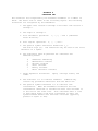
APPENDIX A
CHARACTER SET
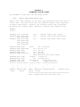
The character set recognized by the Freeware assembler is a subset of
ASCII. The ASCII code is shown in the following figure. The following
characters are recognized by the Assembler:
1. The upper case letters A through Z and lower case letters a
through z.
2. The digits 0 through 9.
3. Five arithmetic operators:
after division).
4. Four logical operators:
+, -, *, / and % (remainder
&, |, ~, and ^.
5. The special symbol characters underscore (_).
and dollar sign ($). The underscore may be used as the first
character of a symbol.
6. The characters used as prefixes for constants and
addressing modes:
#
$
&
@
%
'
Immediate addressing
Hexadecimal constant
Decimal constant
Octal constant
Binary constant
ASCII character constant
7. Three separator characters:
comma.
space, carriage return, and
8. The character "*" to indicate comments. Comments may
contain any printable characters from the ASCII set.
9. The special symbol backslash "\" to indicate line
continuation. When the assembler encounters the line
continuation character it fetches the next line and adds it
to the end of the first line. This continues until a line
is seen which doesn't end with a backslash or until the
system maximum buffer size has been collected (typically
greater or equal to 256).
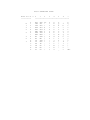
ASCII CHARACTER CODES
BITS 4 to 6 -- 0
1
2
3
4
5
6
7
-----------------------------------------------
B
I
T
S
0
T
O
3
0
1
2
3
4
5
6
7
8
9
A
B
C
D
E
F
NUL
SOH
STX
ETX
EOT
ENQ
ACK
BEL
BS
HT
LF
VT
FF
CR
SO
S1
DLE
DC1
DC2
DC3
DC4
NAK
SYN
ETB
CAN
EM
SUB
ESC
FS
GS
RS
US
SP
:
!
#
$
%
&
'
(
)
*
+
,
.
/
0
1
2
3
4
5
6
7
8
9
:
;
<
=
>
?
@
A
B
C
D
E
F
G
H
I
J
K
L
M
N
O
P
Q
R
S
T
U
V
W
X
Y
Z
[
\
]
^
_
`
a
b
c
d
e
f
g
h
i
j
k
l
m
n
o
p
q
r
s
t
u
v
w
x
y
z
{
;
}
~
DEL
APPENDIX B
ADDRESSING MODES
The Freeware 68332 assembler supports all addressing modes of
the MC68332. These are described briefly in this chapter. For more
detail refer to the MC68332 CPU reference manual.
Operand Format
M68332 Addressing Mode
==============
======================
Dn
Data Register Direct
An
Address Register Direct
(An)
Address Register Indirect (ARI)
(An)+
ARI with Post Increment
-(An)
ARI with Pre Decrement
(d16,An)
ARI with Displacement
(d8,An,Xn.Size*Scale)
ARI with Index (8 bit Displacement)
(bd,(Z)An,(Z)Xn.Size*Scale) ARI with Index (Base Displacement)
Dn
An
Xn
d8
d16
bd
Size
Scale
Z
-
Any Data Register D0 to D7
Any Address Register A0 to A7
Any Address or Data Register
8 bit Displacement
16 bit displacement
32 bit displacement
a size specifier - may be W (Word, 16 bit) or L (Long, 32 bit)
an data object size specifier - may be 1, 2, 4, or 8
indicates suppression of the following parameter in the
effective address calculation
B.1 - Data Register Direct
==========================
The data to be operated upon is contained in the data register
specified in the operand field of the source code. Registers D0 through
D7 are valid.
B.2 - Address Register Direct
=============================
The data to be operated upon is contained in the address
register specified in the operand field of the source code. Registers
A0 through A7 are valid.
B.3 - Address Register Indirect
===============================
The data to be operated upon is contained in the memory location
pointed to by the contents of the address register specified in the
operand field of the source code. Registers A0 through A7 are valid.
B.4 - Address Register Indirect with Post Increment
===================================================
The data to be operated upon is contained in the memory location
pointed to by the contents of the address register specified in the
operand field of the source code. After the operation is performed, the
specified address register is incremented by a value representing the
size of the data oblect in bytes. eg If the operation was on a long
data variable, the address register will by incremented by 4. Registers
A0 through A7 are valid.
B.5 - Address Register Indirect with Pre Decrement
==================================================
The data to be operated upon is contained in the memory location
pointed to by the contents of the address register specified in the
operand field of the source code. Before the operation is performed, the
specified address register is decremented by a value representing the
size of the data oblect in bytes. eg If the operation was on a long
data variable, the address register will by decremented by 4. Registers
A0 through A7 are valid.
B.6 - Address Register Indirect with Displacement
=================================================
The data to be operated upon is contained in the memory location
pointed to by the contents of the address register, plus the fixed
16-bit displacement specified in the operand field. The displacement is
sign-extended to 32 bits before the effective address of the data is
calculated. The contents of the address register are not changed.
Registers A0 through A7 are valid.
B.7 - Address Register Indirect with Index (8-bit Displacement)
===============================================================
The data to be operated upon is contained in the memory location
pointed to by the contents of the address register specified, plus the
specified index register (may be any address or data register), plus the
fixed 8-bit displacement specified in the operand field. The index
register may be optionally scaled (multiplied) by a scale factor of 2,4,
or 8 before it is added to the contents of the address register. The
displacement is sign-extended to 32 bits before the effective address of
the data is calculated. The contents of the address register are not
changed. Registers A0 through A7 are valid for the base register.
B.8 - Address Register Indirect with Index (Base Displacement)
==============================================================
The data to be operated upon is contained in the memory location
pointed to by the contents of the address register specified, plus the
specified index register (may be any address or data register), plus the
fixed 32-bit displacement specified in the operand field. The index
register may be optionally scaled (multiplied) by a scale factor of 2,4,
or 8 before it is added to the contents of the address register. The
displacement is sign-extended to 32 bits before the effective address of
the data is calculated. The contents of the address register are not
changed. Registers A0 through A7 are valid for the base register.
This mode differs from the previous mode (8 bit displacement) mainly in
that the displacement is 32 bits wide, instead of only 8 bits wide, and
that any of the terms (base displacement, index register, or base
address register) may be suppressed by placing a 'Z' in front of it in
the source code.
APPENDIX C
DIRECTIVE SUMMARY
A complete description of all directives appears in Chapter 4.
ASSEMBLY CONTROL
EVEN
Align Assembly Program Counter to word boundary
INCLUDE
Include file into current assembly
ORG
Origin program counter
SECTION
Change to program counter for section 0 through 15
SYMBOL DEFINITION
EQU
Assign permanent value
DATA DEFINITION/STORAGE ALLOCATION
DC(.Size)
Define Constant
DS(.Size)
Define Storage
LISTING CONTROL
OPT l Print source listing from this point
OPT nol
Inhibit printing of source listing from this point
APPENDIX D
ASSEMBLER LISTING FORMAT
The Assembler listing has the following format:
ADDR
OBJECT CODE BYTES SOURCE LINE
ADDR is the 32-bit address of the first byte generated from each line of
source code. The next field lists the generated object code, organized
as three 2-byte words. Finally, the original source code is printed
including the original label, operation, operand, and comment fields.
EXAMPLE
=======
00000000 7374 7269
00000006 0073 0074
0069 006e
00000012 0000 0073
0074 0000
0000 0069
006e 0000
*
0000002a 4ab0 83d0
0000002e 4ab1 99a0
00000034 4ab1 9990
00000038 4abb 00c6
0000003c 4abb 0160
00000042
00000046
0000004a
0000004e
========
^
|
|
Address
Field
6e67
0072
0067
0000
0072
0000
0067
dc.b
dc.w
'string' define text string
'string' same thing using words
dc.l
'string' same again using longs
start
tst.l (za0.w*2)
tst.l (10,a1.l*1)
tst.l (a1.l*1)
tst.l (pc,d0)
ffc2
tst.l (pc,zd0)
*
These should be the brief format.
4a72 10fb
loop tst
-5(a2,d1.w)
4a7b 10ec
tst
*-18(pc,d1.w)
12b2 10fb
done move.b
-5(a2,d1.w),(a1)
12bb 10ec
move.b
*-18(pc,d1.w),(a1)
============== ======= ====== ==================
^
^
^
^
^
^
^
|
|
|
|
|
|
|
|
|
|
|
|
|
|
Object Code
Label Operation Operand Field
Comment Field
Field
Field
Field
=================================================
This is duplicated from the source file
000a
APPENDIX E
S-RECORD INFORMATION
E.1
INTRODUCTION
The S-record output format encodes program and data object modules
into a printable (ASCII) format. This allows viewing of the object
file with standard tools and allows display of the module while
transferring from one computer to the next or during loads between a
host and target. The S-record format also includes information for
use in error checking to insure the integrity of data transfers.
E.2
S-RECORD CONTENT
S-Records are character strings made of several fields which identify
the record type, record length, memory address, code/data, and
checksum. Each byte of binary data is encoded as a 2-character
hexadecimal number: the first character representing the high-order
4 bits, and the second the low-order 4 bits of the byte.
The 5 fields which comprise an S-record are:
TYPE
RECORD LENGTH
ADDRESS
CODE/DATA
CHECKSUM
The fields are defined as follows:
FIELD
----Type
CHARACTERS
---------2
CONTENTS
-------S-record type - S0 through S9
Record
length
2
The count of the character pairs in the
record, excluding the type and record
length.
Address
4, 6,
or 8
The 2-, 3-, or 4-byte address at which
the data field is to be loaded into
memory.
Code/data
0-2n
From 0 to n bytes of executable code,
memory loadable data, or descriptive
information.
Checksum
2
The least significant byte of the one's
complement of the sum of the values
represented by the pairs of characters
making up the record length, address,
and the code/data fields.
Each record may be terminated with a CR/LF/NULL.
E.3
S-RECORD TYPES
Several types of s-records have been defined to accommodate various
encoding, transportation, and decoding needs. The MC68332 Freeware
assembler uses the following types:
S0
S1
E.4
A record containing the filename encoded in ASCII hex
characters. This is a dummy header file which is not used by
Motorola evaluation systems.
A record containing code/data and the 2-byte
address at which the code/data is to reside.
S2
A record containing code/data and the 3-byte address at which
the code/data is to reside
S3
A record containing code/data and the 4-byte address at which
the code/data is to reside
S7
A termination record for a block of S3 records. The address
field may optionally contain the 4-byte address of the
instruction to which control is to be passed. If not
specified, the first entry point specification encountered in
the object module input will be used. There is no code/data
field.
S8
A termination record for a block of S2 records. The address
field may optionally contain the 3-byte address of the
instruction to which control is to be passed. If not
specified, the first entry point specification encountered in
the object module input will be used. There is no code/data
field.
S9
A termination record for a block of S1 records. The address
field may optionally contain the 2-byte address of the
instruction to which control is to be passed. If not
specified, the first entry point specifica
tion encountered in the object module input will be used.
There is no code/data field.
S-RECORD EXAMPLE
The following is a typical S-record module:
S1130000285F245F2212226A000424290008237C2A
S11300100002000800082629001853812341001813
S113002041E900084E42234300182342000824A952
S107003000144ED492
S9030000FC
The module consists of four code/data records and an S9 termination
record.
The first S1 code/data record is explained as follows:
S1
S-record type S1, indicating a code/data record to be
loaded/verified at a 2-byte address.
13
Hex 13 (decimal 19), indicating 19 character pairs,
representing 19 bytes of binary data, follow.
00
Four-character 2-byte address field: hex address 0000,
indicates location where the following data is to be loaded.
The next 16 character pairs are the ASCII bytes of the actual
program code/data.
2A
Checksum of the first S1 record. The checksum is the
complemented sum of byte value of all fields following the S1
field.
The second and third S1 code/data records each also contain $13
character pairs and are ended with checksums. The fourth S1 code/data
record contains 7 character pairs. S2 and S3 records are similiar
except that the address field is 3 bytes and 4 bytes long, respectively.
The S9 termination record is explained as follows:
S9
S-record type S9, indicating a termination record.
03
Hex 03, indicating three character pairs (3 bytes) to
follow.
00
00
Four character 2-byte address field, zeroes.
FC
The two character, one-byte checksum field.
The S6 and S7 termination records are similiar except for the larger
address fields as noted earlier.
APPENDIX F
SYMBOL FILE INFORMATION
F.1
INTRODUCTION
Version 1.2 of the Freeware 68332 assembler introduced a new feature symbol file output. This feature is enabled with the -s option on the
command line. The output format is compatible with the BD32 background
debugger for the CPU32, running on PC-DOS computers. The symbol file is
output at the conclusion of the assembler run, and contains symbols
defined in all files assembled in the run. The symbol file has the same
name as the first source file specified on the assembler command line,
with the file extension set to '.SYM'.
F.2
FILE FORMAT
The format of the symbol file is a series of lines of ASCII text, each
terminated with the DOS standard return/linefeed sequence. The format
for
each line is as follows:
set <symbol name> <hex value>
where <symbol name> represents the symbol's name as entered in the source
program, and <hex value> represents the value assigned to that symbol
during the assembly.
F.3
EXAMPLE
Suppose a source file 'test.s' was created with the following contents.
rambar
ramtst
save
org
dc.w
equ
equ
$4000
2
start move.w
move.w
rts
end
$fffffb00
$fffffb02
address of RAM Base Address Reg
address of RAM Test Register
RAM locations to save contents
rambar,save save contents of rambar
ramtst,save
done
In the above program, four symbols are defined.
using the command line:
Assemble the program
as32 -s test.s
At the end of assembly, two files have been created by the assembler,
'test.s19' containing the object code, and 'test.sym' containing the
symbols and their values. 'Test.sym' contains the following:
set
set
set
set
rambar 0xfffffb00
save 0x4000
ramtst 0xfffffb02
start 0x4002
The hexadecimal value is listed for each symbol, preceeded by the
notation
'0x'.
F.4
DEBUGGING PROGRAMS WITH BD32
This symbol file format is compatible with the BD32 debugger program for
the CPU32. When running BD32, executing the BD32 commands shown below
will load the object file and the symbol file from the preceeding
assembly:
BD32->lo test.s19
(This command typed by user)
.
1 records loaded from test.s19
BD32->do test.sym
(This command typed by user)
BD32->set rambar 0xfffffb00
BD32->set save 0x4000
BD32->set ramtst 0xfffffb02
BD32->set start 0x4002
BD32->
The 'do' command treats the contents of the specified file as a list of
commands to execute. The 'set' command in BD32 defines the given symbol
name and value in BD32's symbol table. At this point, the symbolic names
may be substituted for hexadecimal parameters during debugging work with
BD32.
APPENDIX G
SOFTWARE RELEASE NOTES
VERSION
=======
* 1.0 *
*
* 1.1 *
*
*
*
*
counters
*
* 1.2 *
*
*
*
COMMENTS
========
first release
September 1989
January 1990
fixed list option so it is initially off
errors no longer kill second pass (produces listing file)
errors go to screen (stderr) on pass 1, listing on pass 2
fixed DS pseudo op so zeroes aren't emitted
added support for 16 sections with separate prog.
November 1990
added -s option - symbol table dump to file
fixed silly error so listings (finally) default to 'off'
changed signon prompt to say 'CPU32'
changed line number to 32 BIT long