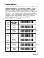
1
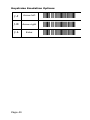
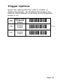
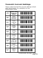
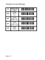
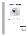
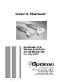
Users Manual Handheld CCD Wedge Interface 25-WEDGE-06 Ver. May 2000 8 Olympic Drive Orangeburg, NY 10962 Tel 845.365-0090 Fax 845.365-1251 www.opticonUSA.com Table of Contents PART I CCD Scanning General Information .......................................... 1 Wedge Interface ............................................... 2 Set Up ............................................................. 3 Scanning .......................................................... 5 User Maintenance ............................................. 6 Troubleshooting ................................................ 7 Technical Specifications ..................................... 9 Ordering Information ....................................... 10 FCC Information .............................................. 11 Warranty ........................................................ 12 Glossary ......................................................... 13 NOTICE Opticon has taken every step to ensure that the information included in this manual is accurate, however we reserve the right to change any specification at any time without prior notice. Part II Bar Code Menu Functions Reset All Defaults ............................................ 17 Computer Type Selection ................................. 18 Symbology Selection ....................................... 19 Symbology Additions ....................................... 21 UPC Settings ................................................... 22 Code 39 Settings ............................................. 25 Codabar Settings ............................................ 27 2 of 5 Settings ................................................ 29 Code 128 & MSI/Plessey Settings .................... 31 Intercharacter Delay ........................................ 32 Scan Code Delay ............................................. 34 Bar Code Length Options ................................. 35 Global Suffix Options ....................................... 36 Keyboard Emulation Options ............................ 37 Keystroke Emulation Options ............................ 38 Trigger Options ............................................... 41 Beeper Settings .............................................. 42 Transmit Current Settings ................................ 43 Read Mode ..................................................... 45 General Information CCD (charged coupled device) scanners are, depending on model type, either contact or near contact scanners. Because CCDs scan automatically when approaching or pointing at a bar code label, their operation is intuitive. CCDs read difficult labels found on curved or irregular surfaces and perform especially well in high ambient light conditions. They are a costeffective, inexpensive alternatives to other scanning technologies. Featuring state-of-the-art imaging technology, CCDs use the same sensor found in facsimile machines or video camcorders. The CCD images the bar code label, then converts the digital signals into data the host computer can understand. By capturing the bar code image all at once, the scanner provides a fast, highly accurate read rate. Miniature surface mount electronics make up the CCD scanners solid state construction. CCDs have no moving mechanical parts and provide years of trouble-free operation. Page 1 Wedge Interface The HLT/ELT series Wedges have built-in intelligence to connect directly to a personal computer without the need for a separate decoder box. Scanned bar code labels appear to the computer as if the data was typed into the keyboard. Normal operation of the keyboard is unaffected. The WEDGE interface is compatible with virtually any application program accepting keyboard input. Advantages • • • • • • • Low cost no separate decoder box required No special software installation or technical support needed Same communication signal format as keyboard Simple installation No external power supply Full featured bar code menu offers user flexibility Uses existing keyboard type Page 2 Set Up Unpacking Remove the scanner from its packaging and inspect it for damage. If the scanner was damaged in transit, call the Opticon Customer Service Dept. at 800-636-0090. Installation A Y connection cable is provided for installation. The scanner is installed or wedged between the keyboard and the computers CPU. The Y cable connects both the scanner and the keyboard to the computer. WARNING! In order to avoid possibility of damage to the computer, install the CCD scanner and Y cable when power to the system is OFF. Page 3 Programming the Scanner This manual provides an easy way of changing certain parameters. A parameter is changed by reading a specific bar code associated to a specific function. To select menu options: 1. Scan Start/End Program Menu. The scanner will beep continuously to indicate that it is ready to be programmed. 2. Make parameter selection from menu (a beep and a green light indicates that the parameter has been scanned). 3. Scan Start/End Program Menu. This completes the operation and the new parameter is saved in memory. The CCD reader is normally programmed as a keyboard wedge for IBMs XT, AT, or PS/2 Models 50, 60, 70 and 80. If the host computer is not one of these models, refer to Computer Type Selection on page 18 to make another selection. B ) A pointing finger indicates scanner NOTE: ( default settings. Page 4 Scanning If the scanner has a switch, depress button on underside to turn the scanner on. Red LED illumination will emit from the scan window. If the scanner does not have a trigger switch, then the LEDs will automatically remain on as long as the computer system is on. good read indicator scan window NOTE: The scanner will not read any bar code label which is wider than the scan window. 1. Approach, point or touch the bar code label with the scan window of the CCD scanner. 2. Scan within a distance of 0 to 1.0" (2.3" window); 0 to 2.5" (3.2" window) from the bar code label. 3. Center the CCD scan window on bar code label for fastest read. 4. The scanner will beep to indicate an audible good read * (if beeper has not been turned off by a menu option). 5. A green LED indicator will visually signal a good read. * The scanner reads all bar code symbologies listed in the menu section of this manual. Page 5 User Maintenance Cleaning the scan window is the only maintenance that is required. ♦ Do not allow any abrasive material to touch the window. ♦ Remove any dirt particles with a damp cloth. ♦ Clean the scan window using a soft cloth or a cotton tipped swab moistened with water. ♦ Do not remove the nose of the scanner. Page 6 Troubleshooting A. If LEDs do not light up when installation instructions are followed: • Make sure there is power to the system. • Recycle computer power. • Verify computer fuses are ok. • Check for loose cable connections. • Are adaptors being used? B. If LEDs light up, but good read beep is not heard and no data appears on the computer: • Make sure the distance between the scanner and bar code label is not greater than the specified depth-of-field when trying to read it. • Verify the bar code label is readable and meets bar code specification. • Check to see if the scanner reads other bar code labels (if yes, the non-reading label may be a label which the scanner is not programmed to decode.) • Verify that the bar code label is not wider than the CCD scan window. CONTINUED ON NEXT PAGE... Page 7 C. If LEDs light up, good read beep is heard but no data appears on the computer: • Check to see that the Computer Type Selection matches the type of computer that you are using. • Change the Intercharacter Delay setting. Depending upon the type of computer that you are using, the intercharacter delay will vary. • If you are using a file sever, an interrupt conflict may arise. Opticon recommends using an RS232C CCD scanner interface on file servers. NOTE: If after performing these checks, the scanner is still not functioning, contact your distributor or call Opticon Technical Support at 800-636-0090. Factory Service When calling Opticon Technical Support, please have the unit model number and several bar code labels readily at hand. The model number is located near the connector end of the cable. Page 8 Technical Specifications Physical Case Material ABS Plastic; Ivory/Grey Dimensions (LxWxH) 2.3" window 5.5 x 2.5 x 2 inches 3.2" window 5.5 x 3.2 x 2 inches Weight 6 oz. Cable Length 5 ft. nominal Optical Photo Detector 2048 Element CCD array Scan Speed 50 scans/sec. Light Source Red LED (λ = 660 nm) Depth of Field (UPC 15 mil) 2.3 window 0 to 1 (63 mm) 3.2 window 0 to 2.5 (25.4 mm) Field Width 2.3" or 3.2" @ contact (optional) Min. Element Width 2.3 window .004" (4 mil) @ contact 3.2 window .006" (6 mil) @ contact Print Contrast 0.45 min. Electrical Supply Voltage Current +5V DC ±10% 60 mA max. Environmental Temperature Operating +32° to +105° F Storage -15° to +140° F Humidity RH (non-condensing) Operating Up to 80% Storage Up to 90% Interface Wedge Keyboard Input Page 9 Ordering Information Accessories Available Part Number Description 28-KYDEX-01 L-Style Hands-free Stand 28-00010-01 Rubber Side-Mount Stand 28-UNVSTD-01 Universal Scanner Stand Page 10 FCC Information This equipment has been tested and is found to comply with the limits for a Class A digital device, pursuant to Part 15 of the FCC Rules. These limits are designed to provide reasonable protection against harmful interference when the equipment is operated in a commercial environment. This equipment generates, uses, and can radiate RF energy and, if not installed and used in accordance with the instruction manual, may cause harmful interference to radio communication. Operation of this equipment in a residential area is likely to cause harmful interference, in which case the user will be required to correct the interference at their own expense. Changes or modifications not expressly approved by the party responsible for compliance could void the users authority to operate this equipment. Page 11 Warranty This scanner is guaranteed for a period of five (5) years from date of shipment from Opticon, including all defects in material and workmanship for the first year and electronics only thereafter. Opticon will, at its option, repair or replace products which prove to be defective in material or workmanship under proper use within the warranty period. Opticon will consider any product out-of-warranty if the unit has been subjected to misuse, accident or incorrect installation. No other warranties are expressed or implied, including but not limited to the implied warranties of merchantability and fitness for a particular purpose. Opticon is not liable for consequential damages. If the scanner must be returned, please contact Opticon to obtain an RMA (Return Merchandise Authorization) number prior to returning the product. The Customer Service Dept. may be reached at 800-636-0090. NOTE: Returned merchandise will NOT be accepted without a RMA number indicated clearly on the outside of the carton. Page 12 Glossary ASCII - American Standard Code for Information Interchange. A 7 bit plus parity code representing 128 letters, numerals, punctuation marks, and control characters. It is a standard data transmission code in the US. Autodiscrimination - The ability of bar code reading equipment to recognize and correctly decode more than one symbology. Bar Code - An automatic identification technology which encodes information into an array of varying width parallel rectangle bars and spaces. Bar Code Density - The number of data characters which can be represented in a linear unit of measure. Bar code density is often expressed in characters per inch. CCD (Charged Coupled Device) - A technology in which scanning is accomplished with an array of LEDs flooding the bar code with light. Check Digit - A digit used to verify a correct symbol code. The scanner inserts the decoded data into an arithmetic formula and checks that the resulting number matches the encoded check digit. Check digits are required for UPC but are optional for other symbologies. Using check digits decreases the chance of substitution errors when a symbol is decoded. Codabar - A discrete self-checking code with a character set consisting of digits 0 to 9 and six additional characters (- $ : / , +). Code 128 - A high density symbology which allows the controller to encode all ASCII characters without adding extra symbol elements. Page 13 Glossary (cont.) Code 3 of 9 (Code 39) - A versatile and widely used alphanumeric bar code symbology with a set of 43 characters types, including all upper case letters, numerals from 0 to 9 , and 7 special characters (- / . + % $ and space). The code name is derived from the fact that 3 of 9 elements representing a character are wide, while the remaining 6 are narrow. Decode - To recognize a bar code symbology and then analyze the content of the specific bar code scanned. Default - A standard setting assigned to a parameter type unless a different setting is assigned to that parameter. Depth of field - The distance between the maximum and minimum plane in which bar code reader is capable of reading symbols. EAN (European Article Number) - This European/International version of the UPC provides its own coding format and symbology standards. Element dimensions are specified metrically. EAN is used primarily in retail. Encode - To translate data into machine readable form using the format and conventions of a specific bar code symbology. Host Computer - A computer that serves other terminals in a network, providing such services as computation, database access, supervisory programs, and network control. Page 14 Glossary (cont.) Interleaved 2 of 5 - A binary code symbology representing character pairs in groups of five bars and five interleaved spaces. Interleaving provides for greater information density. The location of wide elements (bars/spaces) within each group determines which characters are encoded. This continuous code type uses no Inter-character spaces. Only numeric (0 to 9) and START/STOP characters may be encoded. Parameter - A setting that can have a different function assigned to it. Programming mode - The state in which a scanner is configured for parameter settings. Quiet Zone - A clear space, containing no machine readable marks, which precedes the start character of a bar code symbol and follows the stop characters. Read Rate - The ratio of the number of successful reads on the first attempt to scan to the total number of attempts. Resolution - In a bar code system, the narrowest element dimension which can be distinguished by a particular reading device or printed with a particular device or method. Scanner - An electronic device used to scan bar code symbols and produce a digitized pattern that corresponds to the bars and spaces of the symbol. Scanning Mode - The scanner is energized, programmed, and ready to read a bar code. Page 15 Glossary (cont.) Start/Stop Character - A pattern of bars and spaces that provides the scanner with start and stop reading instructions and scanning direction. The start and stop characters are normally to the left and right margins of a horizontal code. Symbology - The structural rules and conventions for representing data within a particular bar code type. UPC (Universal Product Code) - A relatively complex numeric symbology. Each character consists of two bar codes and two spaces, each of which can be any of four widths. The standard symbology for retail food packages in the United States. Wedge - A device that plugs in between a keyboard and a PC. Includes a scanner allowing data to be entered either by a keyboard or scanner. Page 16 Part II Bar Code Menu Functions Reset All Defaults Please note that our scanners are shipped set to the U1 default. This programs the scanner to the settings most commonly used by our customers. Our scanners will work, in most applications, right out of the box. The following options reset all previously programmed options and return the unit to factory default settings. Z9 Start/End Program Menu U1 Reset all defaults ,Z9, ,U1, B B NOTE: ( settingS. ) A pointing finger indicates default Page 17 Computer Type Selection The Wedge interface program is designed to operate on IBM personal computers and compatibles along with a Apple Macintosh PCs. Select the host computer type from the menu below. NOTE: If the scanner has not been set to the correct host computer, the scanner will display random characters on the screen after reading a bar code label. Z9 Start/End Program Menu ,Z9, K0 IBM PC/XT ,K0, K1 IBM AT & compatibles (PS-2/50, 60. 70. 80) ,K1, B K2 IB M PS-2/ 25, 30 ,K2, K3 HP Vectra ,K3, K4 Macintosh (Ranger only) ,K4, KC Laptop*/ SureOne mode (Ranger only) ,KC, * With laptop mode, computer must be turned off and rebooted. Page 18 Symbology Selection The scanner autodiscriminates many bar code symbologies. However, if only one symbology is required, programming the scanner to read only that symbology will speed operation and eliminate read errors. Z9 Start/End Program Menu A0 Read all codes ,A0, B A1 UPC & all variants only ,A1, A2 Code 39 only ,A2, A3 Codabar only ,A3, A4 2 of 5 only ,A4, A5 Code 93 only ,A5, ,Z9, CONTINUED ON NEXT PAGE... Page 19 Symbology Selection Z9 Start/End Program Menu ,Z9, A6 Code 128 only ,A6, A7 MSI/Plessey only ,A7, A8 Code 4 and Code 5 ,A8, Page 20 Symbology Additions Use this menu to add a second, third, fourth, etc. symbology to be read if scanner is not programmed to read all symbologies. To speed operation and eliminate read errors, add only the symbologies that are required. Z9 Start/End Program Menu ,Z9, B0 Enable Code 4 & Code 5 ,B0, B1 Enable UPC & all variants ,B1, B2 Enable Code 39 ,B2, B3 Enable Codabar ,B3, B4 Enable 2 of 5 ,B4, B5 Enable Code 93 ,B5, B6 Enable Code 128 ,B6, B7 Enable MSI/Plessey ,B7, Page 21 UPC Settings Options for UPC-A and UPC-E bar codes. NOTE: Abbreviations: Xmit = transmit; NSC = Number System Character; CD = Check digit Z9 Start/End Program Menu C8 EAN-13 as UPC-A off ,C8, B C9 EAN-13 as UPC-A on ,C9, L0 Enable add-on code ,L0, L1 Disable add-on code ,L1, B M0 UPC-E CD Xmit off ,M0, B M1 UPC -E CD Xmit on ,M1, M2 UPC-A CD Xmit off ,M2, M3 UPC-A CD Xmit on ,M3, B ,Z9, CONTINUED ON NEXT PAGE... Page 22 UPC Settings Z9 Start/End Program Menu ,Z9, M4 UPC-E; NSC = 1 off ,M4, B M5 UPC-E; NSC = 1 on ,M5, M6 Xmit ISBN as EAN-13 ,M6, B M7 Xmit ISBN as UPC-A ,M7, M8 Xmit ISBN w/out CD ,M8, M9 Xmit ISBN with CD ,M9, N0 Xmit UPC-A w/out NSC ,N0, N1 Xmit UPC-A with NSC N2 Xmit UPC-E w/out leading "0" ,N1, B ,N2, B CONTINUED ON NEXT PAGE... Page 23 UPC Settings Z9 Start/End Program Menu ,Z9, N3 Xmit UPC-E with leading "0" ,N3, N4 UPC-E expansion off ,N4, B N5 UPC-E expansion on ,N5, N6 Xmit UPC-A as EAN-13 off ,N6, B N7 Xmit UPC-A as EAN-13 on ,N7, N8 Xmit EAN-13 as ISBN off ,N8, B N9 Xmit EAN-13 as ISBN on ,N9, Page 24 Code 39 Settings Z9 Start/End Program Menu ,Z9, C0 Code 39 CD computation off ,C0, B C1 Code 39 CD computation on ,C1, C2 Code 39 CD Xmit off ,C2, C3 Code 39 CD Xmit on ,C3, C4 Code 39 full ASCII off ,C4, B C5 Code 39 full ASCII on ,C5, D0 Code 39 Xmit start/stop off ,D0, B D1 Code 39 Xmit start/stop on ,D1, CONTINUED ON NEXT PAGE... Page 25 Code 39 Settings Z9 Start/End Program Menu ,Z9, D2 Code 39 single digit on ,D2, D3 Code 39 single digit off D4 Code 39 start/stop as '$' off ,D3, B ,D4, B D5 Code 39 start/stop as '$' on ,D5, Page 26 Codabar Settings Options for Codabar (also known as NW-7). Z9 Start/End Program Menu ,Z9, E0 Codabar CD computation off ,E0, B E1 Codabar CD computation on ,E1, E2 Codabar CD Xmit off ,E2, E3 Codabar CD Xmit on ,E3, E4 Codabar start/stop match off ,E4, E5 Codabar start/stop match on ,E5, B F0 Codabar start/stop xmit off ,F0, F1 Codabar start/stop as ABCD/TN*E ,F1, CONTINUED ON NEXT PAGE... Page 27 Codabar Settings Z9 Start/End Program Menu ,Z9, F2 Codabar start/stop as abcd/tn*e ,F2, F3 Codabar start/stop as ABCD/ABCD ,F3, F4 Codabar start/stop as abcd/abcd F5 Codabar single digit off ,F4, B ,F5, B F6 Codabar single digit on ,F6, Page 28 2 of 5 Settings Options for I 2 of 5 (Interleaved 2 of 5) and D 2 of 5 (Industrial 2 of 5). Z9 Start/End Program Menu ,Z9, G0 I 2 of 5 CD computation off ,G0, B G1 I 2 of 5 CD computation on ,G1, G2 I 2 of 5 CD Xmit off ,G2, G3 I 2 of 5 CD Xmit on ,G3, B G4 I 2 of 5 leading "0" Xmit off ,G4, G5 I 2 of 5 leading "0" Xmit on ,G5, B CONTINUED ON NEXT PAGE... Page 29 2 of 5 Settings Z9 Start/End Program Menu ,Z9, G6 D 2 of 5 CD computation off ,G6, B G7 D 2 of 5 CD computation on ,G7, G8 D 2 of 5 CD Xmit off ,G8, G9 D 2 of 5 CD Xmit on ,G9, B Page 30 Code 128 & MSI/Plessey Settings Z9 C6 C7 Start/End Program Menu Code 128 CD computation off Code 128 CD computation on ,Z9, ,C6, ,C7, B J0 MSI/Plessey CD Xmit on ,J0, B J1 MSI/Plessey 1 CD Xmit off ,J1, J2 MSI/Plessey 2 CD Xmit off ,J2, J3 MSI/Plessey with 1 CD ,J3, B J4 MSI/Plessey with mod 10/mod 10 ,J4, J5 MSI/Plessey with mod 11/mod 11 ,J5, Page 31 Intercharacter Delay For some application programs and IBM compatibles, the scanner may send data faster than the computer or application program can accept. this is called keyboard buffer overrun. If data appears to be missing, random read errors occur or the scanner locks up and will not scan, experiment with the various keyboard timing options listed in the menu to follow. Z9 Start/End Program Menu I0 10 ms delay ,I0, B I1 20 ms delay ,I1, I2 30 ms delay ,I2, I3 40 ms delay ,I3, I4 50 ms delay ,I4, ,Z9, CONTINUED ON NEXT PAGE... Page 32 Intercharacter Delay Z9 Start/End Program Menu ,Z9, I5 60 ms delay ,I5, I6 70 ms delay ,I6, I7 80 ms delay ,I7, Page 33 Scan Code Delay The timing of he keyboard house-keeping codes are set by these commands. Z9 Start/End Program Menu L2 2 ms delay ,L2, B L3 4 ms delay ,L3, L4 6 ms delay ,L4, L5 8 ms delay ,L5, L6 10 ms delay ,L6, L7 12 ms delay ,L7, Page 34 ,Z9, Bar Code Length Options One or two lengths may be selected for free format bar codes. Only free format bar codes of the selected length(s) will be accepted. Z9 Start/End Program Menu ,Z9, H0 Fixed length mode ,H0, H1 Free 2 of 5 length ,H1, H2 Free Codabar length ,H2, H3 Free MSI/Plessey length ,H3, H4 Free Code 39 length ,H4, H5 Free all lengths ,H5, B Page 35 Global Suffix Options * * Adds to all symbologies. The suffix menu enables the user to transmit a carriage return (CR), line feed (LF), tabs, etc. after transmission of the bar code data. NOTE: Only one suffix selection can be programmed at a given time. Z9 Start/End Program Menu ,Z9, O0 No suffix ,O0, O1 Carriage return O2 Line feed ,O2, O3 Carriage return + line feed ,O3, O4 Tab ,O4, O5 Shift+Tab ,O5, OA Arrow down ,OA, Page 36 ,O1, B Keyboard Emulation Options Keyboard emulation options allow the user to emulate the function, arrow and other keys on the computer keyboard. Also, the user has the option of transmitting all upper case or all lower case characters. To begin Keyboard emulation mode, first scan Start, then Keyboard Emulation On, then End. To emulate one of the function or arrow keys, do not scan Start before scanning the keyboard emulation bar code. NOTE: Function key emulation cannot be performed while Full ASCII Code 39 is enabled. Z9 Start/End Program Menu D6 Keyboard emulation mode off ,D6, B D7 Keyboard emulation mode on ,D7, O6 Xmit all upper case ,O6, O7 Xmit all lower case ,O7, O8 Reverse upper & lower case ,O8, O9 Xmit normal ,Z9, ,O9, B Page 37 Keystroke Emulation Options List of all keystroke emulated bar code that are only functional when Keyboard Emulation is on. Scanning Start is not required to read these codes. /-1 F1 */-1* /-2 F2 */-2* /-3 F3 */-3* /-4 F4 */-4* /-5 F5 */-5* /-6 F6 */-6* /-7 F7 */-7* /-8 F8 */-8* /-9 F9 */-9* CONTINUED ON NEXT PAGE... Page 38 Keystroke Emulation Options /-A F10 */-A* /-B F11 */-B* /-C F12 */-C* /-D Page up */-D* /-E Page down */-E* /-F Home */-F* /-G End */-G* /-H Arrow up */-H* /-I Arrow down */-I* CONTINUED ON NEXT PAGE... Page 39 Keystroke Emulation Options /-J Arrow left */-J* /-K Arrow right */-K* /-L Enter */-L* Page 40 Trigger Options Select the appropriate bar code to enable or disable the trigger. By disabling the trigger, the scanner LEDs remain on as long as the computer power is on. Z9 Start/End Program Menu Y0 Enable trigger ,Y0, B Y1 Disable trigger ,Y1, ,Z9, Page 41 Beeper Settings Z9 Start/End Program Menu ,Z9, W0 Disable beeper ,W0, W1 Beep before Xmit ,W1, B W2 Beep after Xmit ,W2, W3 Disable good read light ,W3, W4 Good Read with beep ,W4, W5 Good Read after beep ,W5, Page 42 Transmit Current Settings These codes transmit the current settings (check digit transmission, for example) for the symbologies listed. Z9 Start/End Program Menu ,Z9, Q0 Send software switches ,Q0, Q1 Send Code 39 info ,Q1, Q2 Send Codabar info ,Q2, Q3 Send I 2 of 5 Info ,Q3, Q4 Send D 2 of 5 info ,Q4, Q5 Send Code 128 & 93 info ,Q5, Q6 Send MSI/Plessey info ,Q6, Q7 Send UPC-A info ,Q7, CONTINUED ON NEXT PAGE... Page 43 Transmit Current Settings Z9 Start/End Program Menu ,Z9, Q8 Send UPC-E info ,Q8, Q9 Send EAN-13 & EAN-8 info ,Q9, QA Send Code 4 & Code 5 info ,QA, QB Send system info ,QB, Page 44 Read Mode Select decoding and transmission options from the Read Mode menu. The options Read X Times process the bar code data through the decode algorithm X times before transmitting the data to the keyboard port (the default setting is Read 2 Times). The Single Read option turns off the scanner LEDs immediately after transmission. By selecting the Multi-Read option, the scanner LEDs remain on for a brief period after transmission of the data. Z9 Start/End Program Menu ,Z9, X0 Read once ,X0, X1 Read 2 times ,X1, B X2 Read 3 times ,X2, X3 Read 4 times ,X3, X4 Single Read ,X4, B X5 Multi Read ,X5, Page 45