1
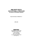
MICRImage
CHECK READER
TECHNICAL REFERENCE MANUAL
Manual Part Number: 99875173 Rev 8
AUGUST 2003
REGISTERED TO ISO 9001:2000
20725 South Annalee Avenue
Carson, CA 90746
Phone: (310) 631-8602
FAX: (310) 631-3956
Technical Support: (651) 415-6800
www.magtek.com
Copyright© 2000-2005
MagTek®, Inc.
Printed in the United States of America
Information in this document is subject to change without notice. No part of this document may be
reproduced or transmitted in any form or by any means, electronic or mechanical, for any purpose,
without the express written permission of MagTek, Inc.
MagTek is a registered trademark of MagTek, Inc.
MICRImage is a trademark of MagTek, Inc.
REVISIONS
ii
Rev Number
1
2
Date
20 Oct 00
27 Jun 01
3
2 Aug 01
4
12 Oct 01
5
9 May 02
6
16 Jul 02
7
27 May 03
8
18 Aug 03
Notes
Initial Release
Front Matter: Changed Limited Warranty to exclude
Scan Bar. Sec 2: Added two cabling diagrams, Terminal
and Auxiliary Device and PC and Net Connection.
Moved Check Path Cleaning to Sec 3.
Front Matter, Agency page: Editorial changes to CE and
UL/CUL.
Front Matter: New Figure 1-1, added MSR.
Section 1: Added description and P/N of MSR. New
Table 1-1, added list of cables. Table 1-2 changed
document size from 9” to 8.5” max.. Editorial Changes.
Section 2: New Figure 2-1, added MSR and editorial
changes.
Section 3: New Figure 3-2, added MSR orientation
Modified Figures 3-3 and 3-4, added new procedure for
opening and closing unit for imaging bar. New Figures 35 and 3-6 for new cleaning procedures. Modified Figure
3-7 for closing.
Sec 1: Added 2 more Configurations and clarified
features; added 1 more Cable; clarified Spec for
interface option. Sec 2: changed Fig 2-4 and 2-5 for
clarification. Sec 3: Clarified Card Reading Procedure.
Front Matter: Added FCC, Part 68 Notice. Changed
MagTek to MagTek throughout. Sec 2: Changed title of
Fig 2-5 from “Net” to “Ethernet or Modem.”
Front Matter: added ISO line to logo, changed Tech
Support phone number, added new warranty statement
Sec 1, Features: Deleted “Horseshoe design….” Added
“Horseshoe check path…” and “Configurable Enhanced
Reading (ER) …”
LIMITED WARRANTY
MagTek warrants that the products sold to Reseller pursuant to this Agreement will perform in accordance with
MagTek’s published specifications. This warranty shall be provided only for a period of one year from the date
of the shipment of the product from MagTek (the “Warranty Period”). This warranty shall apply only to the
original purchaser unless the buyer is authorized by MagTek to resell the products, in which event, this warranty
shall apply only to the first repurchase.
During the Warranty Period, should this product fail to conform to MagTek’s specifications, MagTek will, at its
option, repair or replace this product at no additional charge except as set forth below. Repair parts and
replacement products will be furnished on an exchange basis and will be either reconditioned or new. All replaced
parts and products become the property of MagTek. This limited warranty does not include service to repair
damage to the product resulting from accident, disaster, unreasonable use, misuse, abuse, customer’s negligence,
Reseller’s negligence, or non-MagTek modification of the product. MagTek reserves the right to examine the
alleged defective goods to determine whether the warranty is applicable.
Without limiting the generality of the foregoing, MagTek specifically disclaims any liability or warranty for
goods resold in other than MagTek’s original packages, and for goods modified, altered, or treated by customers.
Service may be obtained by delivering the product during the warranty period to MagTek (20801 S. Annalee
Ave., Carson, CA 90746). If this product is delivered by mail or by an equivalent shipping carrier, the customer
agrees to insure the product or assume the risk of loss or damage in transit, to prepay shipping charges to the
warranty service location and to use the original shipping container or equivalent. MagTek will return the product,
prepaid, via a three (3) day shipping service. A Return Material Authorization (RMA) number must accompany
all returns.
MAGTEK MAKES NO OTHER WARRANTY, EXPRESS OR IMPLIED, AND MAGTEK DISCLAIMS ANY
WARRANTY OF ANY OTHER KIND, INCLUDING ANY WARRANTY OF MERCHANTABILITY OR
FITNESS FOR A PARTICULAR PURPOSE.
EACH PURCHASER UNDERSTANDS THAT THE MAGTEK PRODUCT IS OFFERED AS IS. IF THIS
PRODUCT DOES NOT CONFORM TO MAGTEK’S SPECIFICATIONS, THE SOLE REMEDY SHALL BE
REPAIR OR REPLACEMENT AS PROVIDED ABOVE. MAGTEK’S LIABILITY, IF ANY, TO RESELLER
OR TO RESELLER’S CUSTOMERS, SHALL IN NO EVENT EXCEED THE TOTAL AMOUNT PAID TO
MAGTEK BY RESELLER UNDER THIS AGREEMENT. IN NO EVENT WILL MAGTEK BE LIABLE TO
THE RESELLER OR THE RESELLER’S CUSTOMER FOR ANY DAMAGES, INCLUDING ANY LOST
PROFITS, LOST SAVINGS OR OTHER INCIDENTAL OR CONSEQUENTIAL DAMAGES ARISING OUT
OF THE USE OF OR INABILITY TO USE SUCH PRODUCT, EVEN IF MAGTEK HAS BEEN ADVISED OF
THE POSSIBILITY OF SUCH DAMAGES, OR FOR ANY CLAIM BY ANY OTHER PARTY.
LIMITATION ON LIABILITY
EXCEPT AS PROVIDED IN THE SECTIONS RELATING TO MAGTEK’S LIMITED WARRANTY,
MAGTEK’S LIABILITY UNDER THIS AGREEMENT IS LIMITED TO THE CONTRACT PRICE OF THE
PRODUCTS.
MAGTEK MAKES NO OTHER WARRANTIES WITH RESPECT TO THE PRODUCTS, EXPRESSED OR
IMPLIED, EXCEPT AS MAY BE STATED IN THIS AGREEMENT, AND MAGTEK DISCLAIMS ANY
IMPLIED WARRANTY, INCLUDING WITHOUT LIMITATION ANY IMPLIED WARRANTY OF
MERCHANTABILITY OR FITNESS FOR A PARTICULAR PURPOSE.
MAGTEK SHALL NOT BE LIABLE FOR CONTINGENT, INCIDENTAL, OR CONSEQUENTIAL
DAMAGES TO PERSONS OR PROPERTY. MAGTEK FURTHER LIMITS ITS LIABILITY OF ANY KIND
WITH RESPECT TO THE PRODUCTS, INCLUDING ANY NEGLIGENCE ON ITS PART, TO THE
CONTRACT PRICE FOR THE GOODS.
MAGTEK’S SOLE LIABILITY AND BUYER’S EXCLUSIVE REMEDIES ARE STATED IN THIS SECTION
AND IN THE SECTION RELATING TO MAGTEK’S LIMITED WARRANTY.
iii
FCC WARNING STATEMENT
This equipment has been tested and found to comply with the limits for a Class A digital device, pursuant to Part
15 of FCC Rules. These limits are designed to provide reasonable protection against harmful interference when
the equipment is operated in a commercial environment. This equipment generates, uses, and can radiate radio
frequency energy and, if not installed and used in accordance with the instruction manual, may cause harmful
interference to radio communications. Operation of this equipment in a residential area is likely to cause harmful
interference in which case the user will be required to correct the interference at his own expense.
FCC COMPLIANCE STATEMENT
This device complies with Part 15 Of The FCC Rules. Operation of this device is subject to the following two
conditions: (1) This device may not cause harmful interference. And (2) This device must accept any interference
received, including interference that may cause undesired operation.
CANADIAN DOC STATEMENT
This digital apparatus does not exceed the Class A limits for radio noise for digital apparatus set out in the Radio
Interference Regulations of the Canadian Department of Communications.
Le présent appareil numérique n’émet pas de bruits radioélectriques dépassant les limites applicables aux
appareils numériques de las classe A prescrites dans le Réglement sur le brouillage radioélectrique édicté par les
ministère des Communications du Canada.
CE STANDARDS
Testing for compliance to CE requirements was performed by an independent laboratory. The unit under test was
found compliant to Class A.
UL/CSA
This product is recognized per Underwriter Laboratories and Canadian Underwriter Laboratories 1950.
iv
FCC PART 68 NOTICE
The following refers to MICRImage readers with internal modem only:
This equipment complies with Part 68 of the FCC rules and the requirements adopted by the ACTA. On the
bottom cover of this equipment is a label that contains, among other information, a product identifier in the format
US:AAAEQ##TXXXX. If requested, this number must be provided to the telephone company.
The registration jack Universal Service Order Code (USOC) used by this equipment is RJ-11C. A plug and jack
used to connect this equipment to the premises wiring and telephone network must comply with the applicable
FCC Part 68 rules and requirements adopted by the ACTA. A compliant modular plug is provided with this
product. This equipment is designed to be connected to a compatible modular jack using a telephone cord that is
also compliant. See installation instructions for details.
The REN is used to determine the number of devices that may be connected to a telephone line. Excessive RENs
on a telephone line may result in the devices not ringing in response to an incoming call. In most but not all areas,
the sum of RENs should not exceed five (5.0). To be certain of the number of devices that may be connected to a
line, as determined by the total RENs, contact the local telephone company. The REN for this product is part of
the product identifier that has the format US:AAAEQ##TXXXX. The digits represented by ## are the REN
without a decimal point (e.g., 03 is a REN of 0.3).
If the MICRImage with internal modem equipment causes harm to the telephone network, the telephone company
will notify you in advance that temporary discontinuance of service may be required. But if advance notice isn't
practical, the telephone company will notify the customer as soon as possible. Also, you will be advised of your
right to file a complaint with the FCC if you believe it is necessary.
The telephone company may make changes in its facilities, equipment, operations or procedures that could affect
the operation of the equipment. If this happens the telephone company will provide advance notice in order for
you to make necessary modifications to maintain uninterrupted service.
If you experience trouble with this equipment, refer to the page titled Limited Warranty near the front of this
manual for contact, repair or warranty information. If the equipment is causing harm to the telephone network,
the telephone company may request that you disconnect the equipment until the problem is resolved.
There are no user serviceable parts on the modem contained inside this equipment.
Connection to party line service is subject to state tariffs. Contact the state public utility commission, public
service commission or corporation commission for information.
If your business has specially wired alarm equipment connected to the telephone line, ensure the installation of
the MICRImage with internal modem does not disable your alarm equipment. If you have questions about what
will disable alarm equipment, consult your telephone company or a qualified installer.
v
TABLE OF CONTENTS
SECTION 1. OVERVIEW............................................................................................................................. 1
CONFIGURATION ................................................................................................................................... 1
FEATURES .............................................................................................................................................. 1
ACCESSORIES........................................................................................................................................ 2
SPECIFICATIONS.................................................................................................................................... 2
SECTION 2. INSTALLATION ..................................................................................................................... 5
REQUIREMENTS..................................................................................................................................... 5
CABLING PROCEDURE.......................................................................................................................... 6
SECTION 3. OPERATION........................................................................................................................... 9
CHECK READING PROCEDURE ........................................................................................................... 9
CARD READING PROCEDURE............................................................................................................ 10
LED INDICATORS ................................................................................................................................. 11
CLEANING ............................................................................................................................................. 11
Opening the Unit ................................................................................................................................ 11
MSR Cleaning Card ........................................................................................................................... 11
Cleaning Check Path and Imager ...................................................................................................... 12
Closing the Unit .................................................................................................................................. 14
SECTION 4. TROUBLESHOOTING GUIDE............................................................................................. 15
REQUIREMENTS................................................................................................................................... 15
SET-UP................................................................................................................................................... 15
APPENDIX A. INTERFACE CABLE PIN LISTS ...................................................................................... 23
APPENDIX B. ASCII CODES ................................................................................................................... 25
APPENDIX C. CHECK READING ............................................................................................................ 27
E13-B CHARACTER SET ...................................................................................................................... 27
CMC-7 CHARACTER SET..................................................................................................................... 27
CHECK LAYOUTS ................................................................................................................................. 28
MICR FIELDS......................................................................................................................................... 29
1-Transit Field .................................................................................................................................... 29
2-On-Us Field ..................................................................................................................................... 30
3-Amount Field ................................................................................................................................... 30
4-Auxiliary On-Us Field ...................................................................................................................... 30
vi
FIGURES
Figure 1-1.
Figure 2-1.
Figure 2-2.
Figure 2-3.
Figure 2-4.
Figure 2-5.
Figure 3-1.
Figure 3-2.
Figure 3-3.
Figure 3-4.
Figure 3-5.
Figure 3-6.
Figure 3-7.
Figure 4-1.
Figure C-1.
Figure C-2.
MICRImage Check Reader with MSR .....................................................................................viii
MICRImage with MSR ............................................................................................................... 5
DB25 Connection....................................................................................................................... 6
Cabling – Single PC................................................................................................................... 7
Cabling –Terminal and Auxiliary Device.................................................................................... 8
Cabling – PC and Ethernet or Modem Connection ................................................................... 8
Check Orientation - Insertion..................................................................................................... 9
Optional Magnetic Swipe Reader Orientation ......................................................................... 10
Opening the Unit...................................................................................................................... 12
Cleaning Check Path and Imager............................................................................................ 12
Activating the Cleaning Swab .................................................................................................. 13
Cleaning the Imager ................................................................................................................ 13
Closing the Unit ....................................................................................................................... 14
Sensor Location....................................................................................................................... 21
Personal Checks .................................................................................................................... 28
Business Checks..................................................................................................................... 29
TABLES
Table 1-1.
Table 1-2.
Table 3-1.
Table A-1.
Table C-1.
MICRImage Cables..................................................................................................................... 2
Specifications .............................................................................................................................. 3
LED indicators........................................................................................................................... 11
DB9, DB25 Interface Connector Pin List (P/N 22410302) ..................................................... 23
CMC-7 Nonnumeric Characters............................................................................................... 28
vii
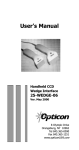
Figure 1-1. MICRImage Check Reader with MSR
viii
SECTION 1. OVERVIEW
The MICRImageTM Check Reader is both a MICR Reader (Magnetic Ink Character Recognition)
and a check-imaging device. The MICRImage reads the MICR character set at the bottom of a
check, and the Imager produces a digitized image of the entire check. The characters and the
image can be transmitted to a Host device. The Host device then uses a specific authorization or
verification process to validate a business transaction.
The MICRImage Reader improves accuracy and speed because there is no manual data entry;
therefore there are no keying errors or unwanted delays.
Both the MICR Reader and the Imaging device will communicate with the Host system using a
standard RS-232 interface (contact the factory for other interfaces). MICR data is transmitted as
ASCII characters (See Appendix B). The MICRImage Reader has the capability of supporting
some hardware handshaking signals.
An optional three-track MSR autodiscriminates different card formats: ISO (International
Standards Organization), CDL (California Drivers License), or AAMVA (American Association
of Motor Vehicle Administrators).
CONFIGURATION
Configurations are as follows:
Part Number
22410002
22410003
22410004
22410005
22410006
22410007
Description
MICRImage, RS-232
MICRImage, RS-232, with 3-Track MSR
MICRImage, RS-232, with Ethernet
MICRImage, RS-232, with Ethernet, 3-Track MSR
MICRImage, RS-232, with V. 34 Modem
MICRImage, RS-232, with V. 34 Modem, 3-Track MSR
FEATURES
The following is a list of features of the MICRImage Reader:
• Full MICR check reader compatible with existing applications
• Horseshoe check path design allows capture of MICR data and check image in a single pass
• Configurable Enhanced Reading (ER) feature allows for automated confirmation of MICR
data by comparing the results of multiple MICR reads (up to 3 reads).
• Automatic parsing of MICR fields: transit, account, etc.
1
MICRImage Check Reader
•
•
•
•
•
•
•
•
•
•
Extensive list of formats to transmit MICR data.
Capable of scanning 200 dpi image of entire front of check
CCITT G4 Image Compression
Ability to send complete image or user-specified portions
Supports dual interface paths, one for MICR, one for image data
Dual RS-232 Interface Support
Models available with Ethernet or V. 34 Modem
Optional 3-track MSR (Magnetic Stripe Reader)
Reads E13-B and CMC-7 MICR fonts
Dynamic Thresholding for image background removal
ACCESSORIES
Accessories available for the MICRImage Reader include:
•
•
•
•
•
•
Host Interface Cables (See Table 1-1)
AC Power Adapter with Cable, 120VAC to 12 VDC, 1.5 Amp, Part Number 64300090
MICRbase Program, Part Number 22000021
Sample Checks, Part Number 96530005
Cleaning Cards P/N 96700004
Cleaning Swabs P/N 97200078
Table 1-1. MICRImage Cables
Part Number
22410302
22410306
22410307
22410308
22410309
22410310
Description
RS232, DB9F, gray, 8 ft.
RS232, DB9F + RS232, DB9F, gray, 8 ft.
RS232, DB9F + Ethernet, RJ8 socket, gray, 8 ft.
RS232, PC-DB9F + RS-232-DB25M, gray
RS232, PC-DB9F + RS-232-DB9M, gray
RS232, PC-DB9F + Modem RJ-11 Socket
SPECIFICATIONS
Table 1-2 lists the specifications for the MICRImage Reader.
2
Section 1. Overview
Table 1-2. Specifications
Reference Standards
Power Input
Current
(Idle)
(Operating)
MTBF
Document Speed
Document Size
Image Resolution
MICR fonts supported
Interface Options
Dimensions
Weight:
Connector: Power and
Communication
OPERATING
ANSI X9.27
12VDC regulated, 1.5 Amp
300 mA
1.5 A Max
Electronics: 125,000 hours
Check Read Head: 1,000,000 passes
MSR Read head: 1,000,000 passes
10 ips
4"x 8.5" Maximum
200 dpi
E13-B
CMC-7
Primary: RS-232, RS-485, IBM 4683
Secondary: RS-232, Ethernet 10 Base-T, V.34 Modem
MECHANICAL
Length 9.0”, Width 3.9”, Height 6.0”
2.5 lbs. Adapter included
DB25 female
ENVIRONMENTAL
Temperature
Operating
Storage
Humidity
Operating
Storage
Altitude
Operating
Storage
0oC to 50oC (32oF to 122oF)
-30oC to 70oC (-22oF to 158oF)
10% to 90% noncondensing
Up to 100% noncondensing
0 -10,000 ft (0 - 3,048m)
0 - 50,000 ft (0 - 15240m)
3
MICRImage Check Reader
4
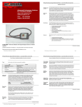
SECTION 2. INSTALLATION
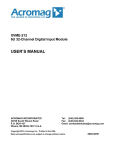
The installation for the MICRImage Check Reader is described below. Figure 2-1 shows the
unit with the MSR.
Card Path
Easy-Access
Latch
Check Path
LED
Figure 2-1. MICRImage with MSR
REQUIREMENTS
The following is required for the Installation:
• MICRImage
• Interface Cable,
• Power Adapter 12 VDC, 1.5 Amp
5
MICRImage Check Reader
CABLING PROCEDURE
The pin lists for all connections are shown in Appendix A. Perform the following steps:
1.
Connect the male DB25 connector to the MICRImage as shown in Figure 2-2.
Easy-Access Latch
LED
Pin 1
Pin 14
Pin 13
Pin 25
Pin 13
Pin 25
Pin 14
Pin 1
Figure 2-2. DB25 Connection
2.
Connect the DB9 connector to the PC as shown in Figure 2-3, 2-4, and 2-5.
3.
Connect RJ45 Jack to the network connection as indicated in Figure 2-5.
4.
On the AC power adapter, connect the jack to the plug on the cable.
5.
On the AC power adapter, connect the plug to the wall outlet.
6.
The LED indicator on the MICRImage Reader should turn on to a steady green. The LED
indicator is located on the slot where the check is first inserted for reading (see Figure 2-1).
6
Section 2. Installation
Caution
Do not place the MICRImage Reader within 6 inches of a
computer monitor or power supply. These devices may cause
undesirable interference with the check reading operation.
For a single PC, install the MICRImage cables as shown in Figure 2-3.
P/N 22410302
MICRImage
12 VDC
Power
Adapter
Figure 2-3. Cabling – Single PC
7
MICRImage Check Reader
For a Terminal and Auxiliary Device, install the MICRImage cables as shown in Figure 2-4.
12 VDC
Power
Adapter
P/N 22410306
Terminal
MICRImage
RS-232 Peripheral
Figure 2-4. Cabling –Terminal and Auxiliary Device
For a PC and Network connection, install the MICRImage cables as indicated in Figure 2-5.
12 VDC
Power
Adapter
MICRImage
P/N 22410307
(Ethernet)
or
22410310
(Modem)
To Network
Connection
or
Phone Jack
Figure 2-5. Cabling – PC and Ethernet or Modem Connection
8
SECTION 3. OPERATION
This section contains check and card reading and cleaning procedures and LED indicator states.
CHECK READING PROCEDURE
1.
Orient the check so the MICR line is down and the printed side faces the center of the
MICRImage as indicated in Figure 3-1.
2.
Drop the check so the leading edge is in the open slot. Slide the check forward.
3.
When the MICRImage detects the presence of the check, the motor will turn on. At this
time gently urge the check forward until the unit grabs the check. When this happens,
release the check. The check will then be transported around the check path and will exit
through the other side.
4.
After the check is read, the MICRImage will transmit the data as specified by the
parameters.
5.
Remove the check.
2
Slowly Slide Check Forward
Until Reader Pulls Check In
Check Flush
1 Place
Onto Entry Slot
Figure 3-1. Check Orientation - Insertion
9
MICRImage Check Reader
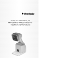
CARD READING PROCEDURE
1.
Orient the card so that the magnetic stripe is down and facing away from the logo on the
unit and toward the wide color stripe on the MRS, as indicated in Figure 3-2.
2.
Slide the card in one motion from the top of the unit down through the slot as indicated in
the illustration.
3.
After the card is read, the MICRImage will transmit the data as specified by the
parameters.
Figure 3-2. Optional Magnetic Swipe Reader Orientation
10
Section 3. Operation
LED INDICATORS
Table 3-1 describes the LED indicator conditions for check and card reading operations. The
LED indicator is located below the slot where the check is first inserted for reading.
Table 3-1. LED indicators
LED INDICATOR
DESCRIPTION
OFF
Power off
SOLID GREEN
Ready to read check or card
Check
read error
OFF→ SOLID RED
Good read
OFF→ SOLID GREEN
FLASH GREEN
Needs initialization*
FLASH RED/GREEN
Magnetic Interference Detected
FLASH RED/GREEN
Data sensor blocked (motor does not run)*
FLASH RED
Motor sensor blocked (motor does not run)*
*Refer to “Section 4. Troubleshooting Guide.”
CLEANING
Clean the outside of the MICRImage unit with a soft, damp cloth and wipe with a dry cloth.
Caution
To avoid damaging the read head, do not get the inside of the
check or card paths wet.
Use the Cleaning Card, P/N 96700004, on the MSR as described below. Use the Cleaning Swab,
P/N 97200078, to clean the Imager Scan Bar as shown and described below.
Opening the Unit
To open the check path and Imager, grip the access latch, and pull up and then back as shown in
Figure 3-3.
MSR Cleaning Card
Orient the cleaning card similar to Figure 3-2. Swipe the card two or three times to clean the
head.
11
MICRImage Check Reader
Pull Latch Up Then Back
Easy-Access Latch
Figure 3-3. Opening the Unit
Cleaning Check Path and Imager
1.
When the unit is open, as shown in Figure 3-4, check the path for debris. To clean, turn
the unit over and tap gently on the bottom.
Imager
Alignment
Alignment
Hole
Pin
Easy-Access
Latch
Figure 3-4. Cleaning Check Path and Imager
2.
12
Check the Imager to ensure there is no build-up of ink or paper debris.
Section 3. Operation
3.
To clean the Imager, use the cleaning swab, shown in Figure 3-5. Activate the swab by
bending the plastic tube until you hear a snap.
Figure 3-5. Activating the Cleaning Swab
4.
Wait until the liquid moves into the sponge tip. It should be damp when touched.
5.
When the tip of the swab is damp, clean the Imager by wiping the swab up and down the
Imager as indicated in Figure 3-6.
Figure 3-6. Cleaning the Imager
13
MICRImage Check Reader
Closing the Unit
1. Hold the unit as shown in Figure 3-7. Push the covers together while ensuring
alignment of the pin and hole.
2. The unit is properly closed when the two panels are flush and the latch has "clicked"
into position.
Imager
Alignment
Alignment
Pin
Hole
To Close:
Push Panel Back And
Ensure Alignment Pin
And Hole Match.
Easy-Access
Latch
Figure 3-7. Closing the Unit
14
SECTION 4. TROUBLESHOOTING GUIDE
REQUIREMENTS
• Personal Computer.
• Interface Cable, Host End = DB9 female, Part Number 22410302.
• AC adapter, P/N 64300090.
• MICRbase Program, P/N 22000021
• Sample checks, P/N 96530005.
• A small bottle of compressed air.
SET-UP
1.
2.
3.
4.
5.
Plug DB25connector of the RS232 cable into the MICRImage Reader.
Plug the DB9 connector of the RS232 cable into the PC.
Power on the MICRImage Reader.
Run the MICRbase program on the PC.
Start trouble-shooting procedure at Step 00.
00
Check LED
Check the status of the LED indicator:
◊ off, continue to step 01.
◊ green, continue to step 02.
◊ blinking red, continue to step 11.
◊ blinking green, continue to step 16.
◊ blinking red/green, continue to 12.
◊ red or orange, continue to step 17.
15
MICRImage Check Reader
01
Check the Power to the MICRImage Reader
Possible causes for this problem are:
• AC adapter connection to outlet - make sure the AC adapter is securely connected to outlet
on the wall or power strip.
• AC adapter connection to MICRImage Reader - make sure the AC adapter is securely
connected to the power jack on the Cable.
• Power strip - if using a power strip, make sure the strip is connected to outlet on the wall and
the switch on the strip is turned on.
• AC adapter is defective - replace the AC adapter.
Determine if any of the conditions described above are true:
◊ If yes, rectify and continue to step 00.
◊ If no, continue to step 17.
02
Read a check
Read a check through the MICRImage Reader:
◊ If the check is transported all the way around the check path, continue to step 03.
◊ If the check gets "stuck" in the check path, continue to step 10.
◊ If the motor does not turn on, continue to step 17.
03
Did PC receive data?
After the check is read, did the PC receive any data?
◊ If yes, continue to step 04.
◊ If no, continue to step 05
16
Section 4. Troubleshooting Guide
04
Analyze data
Analyze the data received by the PC:
◊ If the data is good, continue to step 15.
◊ If the data contains one or more '?', continue to step 06.
◊ If the data is missing characters, continue to step 07.
◊ If the data is garbled, continue to step 08.
◊ If the data is good but not what is expected, continue to step 09.
05
Verify parameters
Use MICRbase to verify the following parameters:
• "Send Data After Error" - if this option is set to NO, the MICRImage Reader will not send
any data after a read error. Use SET-MICR to change this option to YES.
• "Use CTS/DSR" - if this option is set to USE, the MICRImage Reader will not send any data
unless the CTS and DSR signals are enabled. Use SET-MICR to change this option to
IGNORE.
Determine if any of the conditions described above are true:
◊ If yes, rectify and continue to step 02.
◊ If no, continue to step 13.
06
Read error
Possible causes for this problem are:
• Interference - the MICRImage Reader may be too close to a monitor, AC adapter or
magnetic device. Move the MICRImage Reader away from the source of interference.
• Printing problem - the check being read may not meet the requirements of the ANSI
Standards. Use one the sample checks provided by MagTek .
• Feeding the check - do not hold on to the check as it goes around the path. Release the check
immediately after the MICRImage Reader "grabs" it. Also, make sure that the front end is
not tilted up while the check is being read.
Determine if any of the conditions described above are true:
◊ If yes, rectify and continue to step 02.
◊ If no, continue to step 10.
17
MICRImage Check Reader
07
Missing characters
Possible causes for this problem are:
• Character rate - the character rate at which the MICRImage Reader is transmitting data may
be too fast for the PC. Use MICRbase to set the "Inter-character Delay" option to YES.
• Feeding the check - When feeding the check, make sure that the MICR line is at the bottom
and the printed side of the check is facing the MagTek logo on the MICRImage Reader.
Determine if any of the conditions described above are true:
◊ If yes, rectify and continue to step 02.
◊ If no, continue to step 08.
08
Communication parameters do not match
Verify that the communication parameters of the MICRImage Reader match the parameters of
the PC. Use MICRbase to verify/change the communication parameters.
Determine if the condition described above is true:
◊ If yes, rectify and continue to step 02.
◊ If no, continue to step 14.
09
Incorrect Format
Possible causes for this problem are:
• Incorrect Format Number - the current Check data format in the MICRImage Reader is not
the desired format. Use MICRbase to verify/change the format.
• Incorrect Message Format - the current Message format in the MICRImage Reader is not the
desired format. Use MICRbase to verify/change the Message format.
Determine if any of the conditions described above are true:
◊ If yes, rectify and continue to step 02.
◊ If no, continue to step 17.
18
Section 4. Troubleshooting Guide
10
Path is obstructed
Foreign debris is obstructing the check path:
• Loose debris - power off the MICRImage Reader and refer to Section 3, Check Path
Cleaning.
• Wedged debris - the debris is wedged in and cannot be removed with the procedure described
above.
Is the foreign debris removable?
◊ if yes, remove and continue to step 02.
◊ If no, continue to step 17.
11
Motor sensor is blocked
The Motor sensor may be blocked by dust build-up or foreign debris (see Figure 5-1). Use forced
air to clean the sensor.
Power off the MICRImage Reader and then power on again, observe the LED indicator:
◊ If the LED indicator blinks red, continue to step 17.
◊ Any other LED indicator status, continue to step 00.
12
Data sensor is blocked
The data sensor may be blocked (see Figure 4-1). Refer to Section 3 for access and use forced air
to clean the sensor.
Power off the MICRImage Reader and then power on again, observe the LED indicator:
◊ If the LED indicator blinks red/green, continue to step 17.
◊ Any other LED indicator status, continue to step 00.
19
MICRImage Check Reader
13
No MICR data detected
Possible causes for this problem are:
• No MICR characters - the ink used to print the MICR characters does not have magnetic
properties. Try one of the sample checks provided by MagTek.
• Feeding the check - When feeding the check, make sure that the MICR line is at the bottom
and the printed side of the check is facing the MagTek logo on the MICRImage Reader.
Determine if any of the conditions described above are true:
◊ If yes, rectify and continue to step 02.
◊ If no, continue to step 14.
14
Cable problem
Possible causes for this problem are:
• Loose connection - the cable connector on the PC or the MICRImage Reader may be loose.
Make sure that both connectors are tightly connected.
• Damaged cable - the connectors, pins or wires in the cable may be damaged. Replace cable.
Determine if any of the conditions described above are true:
◊ If yes, rectify and continue to step 02.
◊ If no, continue to step 17.
15
No problem found
The MICRImage Reader is operating properly. If you have additional concerns or requirements
please contact your MagTek representative.
16
Read Insta-Change check
Read Insta-Change check with the appropriate settings. Return to step 00. If condition persists,
continue to step 17.
17
20
Return MICRImage Reader to MagTek
Section 4. Troubleshooting Guide
The MICRImage Reader has a problem that needs further analysis, testing, and possibly repair.
Please contact the MagTek Help Desk at (888) 624-8350, and make arrangements to send the
unit back to MagTek. Include a detailed description of the problem.
↑
Motor Sensor
Data Sensor →
Exit Sensor
↓
Figure 4-1. Sensor Location
21
MICRImage Check Reader
22
APPENDIX A. INTERFACE CABLE PIN LISTS
The pin list for the DB9 and DB25 Interface Connectors are shown in Table A-1.
Table A-1. DB9, DB25 Interface Connector Pin List (P/N 22410302)
P1 PIN
NUMBER
DB-9
P1 SIGNAL
(Host as
Reference)
2
RXD
3
P2 PIN
NUMBER
P2 DB-25
SIGNAL
Received Data. Receives data
from the MICRImage Reader to
the Host.
11
TXD
TXD
Transmitted Data. Transmits
data from the Host to the
MICRImage Reader.
21
RXD
5
GND
Ground
16
GND
7
RTS
Request to Send. Sends a
signal to the MICRImage Reader
to indicate that the Host is ready
to receive data.
10
CTS
8
CTS
Clear to Send. Receives a signal
from the MICRImage Reader to
indicate that the MICRImage
Reader is ready to send data.
23
RTS
6
DSR
Data Set Ready.
4
DTR
Data Terminal Ready.
13
12V
25
12V
12
GND
24
GND
22
DTR
9
DSR
SHELL
(DRAIN
WIRE)
DESCRIPTION
SHELL
(DRAIN WIRE)
23
MICRImage Check Reader
24
APPENDIX B. ASCII CODES
The following is a listing of the ASCII (American Standard Code for Information Interchange)
codes. ASCII is a 7-bit code, which is represented here with a pair of hexadecimal digits.
ASCII
NUL
SOH
STX
ETX
EOT
ENQ
ACK
BEL
BS
HT
LF
VT
FF
CR
SO
SI
DLE
DC1
DC2
DC3
DC4
NAK
SYN
ETB
CAN
EM
SUB
ESC
FS
GS
RS
US
Hex value
00
01
02
03
04
05
06
07
08
09
0A
0B
0C
0D
0E
0F
10
11
12
13
14
15
16
17
18
19
1A
1B
1C
1D
1E
1F
ASCII
SP
!
"
#
$
%
&
'
(
)
*
+
,
.
/
0
1
2
3
4
5
6
7
8
9
:
;
<
=
>
?
Hex Value
20
21
22
23
24
25
26
27
28
29
2A
2B
2C
2D
2E
2F
30
31
32
33
34
35
36
37
38
39
3A
3B
3C
3D
3E
3F
ASCII
@
A
B
C
D
E
F
G
H
I
J
K
L
M
N
O
P
Q
R
S
T
U
V
W
X
Y
Z
[
\
]
^
_
Hex Value
40
41
42
43
44
45
46
47
48
49
4A
4B
4C
4D
4E
4F
50
51
52
53
54
55
56
57
58
59
5A
5B
5C
5D
5E
5F
ASCII
`
a
b
c
d
e
f
g
h
i
j
k
l
m
n
o
p
q
r
s
t
u
v
w
x
y
z
{
|
}
~
DEL
Hex Value
60
61
62
63
64
65
66
67
68
69
6A
6B
6C
6D
6E
6F
70
71
72
73
74
75
76
77
78
79
7A
7B
7C
7D
7E
7F
25
MICRImage Check Reader
26
APPENDIX C. CHECK READING
The characters printed on the bottom line of commercial and personal checks are special. They
are printed with magnetic ink to meet specific standards . These characters can be read by a
MICRImage Reader at higher speeds and with more accuracy than manual data entry. Two
MICR character sets are used world wide; they are: E13-B and CMC-7. The E13-B set is used
in the US, Canada, Australia, United Kingdom, Japan, India, Mexico, Venezuela, Colombia, and
the Far East. The CMC-7 set is used in France, Spain, other Mediterranean countries, and most
South American countries.
E13-B CHARACTER SET
The MICR font character set E13-B includes digits 0 through 9 and four symbols. The numbers
found on U.S. checks are of the E13-B character set. The numbers and symbols of E13-B are as
follows:
Transit symbol
Dash Symbol
On-Us Symbol
Amount Symbol
CMC-7 CHARACTER SET
The numbers and symbols of the CMC-7 character set are as follows:
SI
SII
SIII
SIV
S5
27
MICRImage Check Reader
The nonnumeric CMC-7 characters are translated by the MICRImage Reader as shown in Table
C-1.
Table C-1. CMC-7 Nonnumeric Characters
CMC-7 Character
MICRImage Reader
Output
A
B
C
D
E
SI
SII
SIII
SIV
SV
CHECK LAYOUTS
Personal checks with MICR fields are shown in Figure C-1. Business checks are shown in
Figure C-2. The digits 1 through 4 in the illustrations are described below under MICR Fields.
6.00”
2.75”
1
2
Figure C-1. Personal Checks
28
3
Appendix C. Check Reading
8.75”
3.67”
4
1
2
3
Figure C-2. Business Checks
MICR FIELDS
The numbers 1 through 4 refer to the numbers below the checks on the illustration and represent
the 4 MICR fields.
1-Transit Field
The Transit field is a 9-digit field bracketed by two Transit symbols. The field is subdivided as
follows:
• Digits 1-4
• Digits 5-8
• Digit 9
Federal Reserve Routing Number
Bank ID Number (American Banking Association)
Check Digit
29
MICRImage Check Reader
2-On-Us Field
The On-Us field is variable, up to 19 characters (including symbols). Valid characters are digits,
spaces, dashes, and On-Us symbols. The On-Us field contains the account number and may also
contain a serial number (Check number) and/or a transaction code. Note that an On-Us symbol
must always appear to the right of the account number.
3-Amount Field
The Amount field is a 10-digit field bracketed by Amount symbols. The field is always zerofilled to the left.
4-Auxiliary On-Us Field
The Auxiliary On-Us field is variable, 4-10 digits, bracketed by two On-Us symbols. This field
is not present on personal checks. On business checks, this field contains the check serial
number.
30