1
USER MANUAL
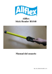
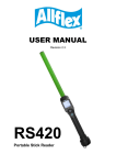
RS320 series ISO Compatible RFID STICK READER
With integral battery pack and LCD readout
User Manual RS320 Eng - Rev B2
Allflex EID Readers
with Dynamic Tuning NetworkTM
REF 02 / Oct 2005.
Congratulations for your acquisition of an Allflex EID reader.
This device is equipped with the new “DTN - Dynamic Tuning Network®” technology,
an exclusive Allflex innovation (patent pending).
The “DTN - Dynamic Tuning NetworkTM” technology provides a significant
improvement of reader performance in two areas: reading distance and noise
immunity. This is obtained by dynamically optimizing the electrical characteristics of
the reader antenna during tag activation and reception cycles.
Readers equipped with Allflex’s Dynamic TuningTM technology deliver increased
activation signal level, improved tag signal reception and improved noise immunity,
together yielding improved reader performance
2
Preparing for use
It is very important to carry out the following three steps before
using the Stick Reader.
Step 1: Installing the battery pack in the Stick Reader
3
Step 2: Charging the battery pack.
2
Charging option.
Ref: 68000017
Ref: 68100020
4
Step 3: Activating the RS320 Stick Reader and read test
5
Stick Reader Power Supply
Required Power supply conditions
The RS320 Stick Reader contains a removable, rechargeable 9.6 VDC NiMH battery
pack, which serves as its primary power source. Alternatively, the RS320 Stick Reader
can be powered using the VAC mains charger/adapter or via any other DC source with
a voltage between 9 VDC and 12 VDC that has a minimum 1A current capability, such
as a 12VDC car battery or PW50/PW250 series Allflex batteries.
VAC mains adapter
The RS320 Stick Reader can be powered using the mains charger/adapter regardless of
the state of charge of the battery pack. The VAC mains adapter can be used as a power
source even if the battery pack has been taken out of the Stick Reader.
i
The Stick Reader can be used when its battery pack is being charged.
When not used for long periods
The battery pack must always be removed from the Stick Reader if it is not used for
long periods. It is advisable to recharge the battery pack once every three months to
preserve battery lifetime.
i
The Stick Reader is protected against accidental reverse polarity voltage
application and will not be damaged by such.
The RS320 Stick Reader is only designed to operate with the battery pack
supplied. The RS320 Stick Reader does not work with any category of
disposable or rechargeable individual battery.
The Stick Reader battery pack is affected by temperature. At 0°C, the battery
pack only supplies about half its specified energy capacity. At lower
temperatures, it may be ineffective. When the RS320 Stick Reader is used at
low temperatures, use an external power source such as the Allflex PW50
battery pack. In this case, we recommend placing the PW50 close to the user's
body.
Do not store the battery pack and Stick Reader at temperatures above 50°C.
Recharge the battery pack every 3 months if it is not used.
6
Activating the Stick Reader
When the Stick Reader is powered up, the LCD readout appears as shown below:
0000
READY TO
READ
This power-on message indicates that the Stick Reader's internal ID code memory has
been cleared and that the Stick Reader is ready to read new tags. If the reader has been
previously used and ID codes are stored in memory, the LCD readout will be as
follows:
0012
HDX ISO:
982 000006975374
In this display, the four digits on the left of the upper line indicate the tag counter; the
information located to the right of this line displays the tag type. On the lower line, the
3 characters of the ISO country code or manufacturer code are displayed, followed by
the 12-digit decimal ISO national ID code.
Display formats for other tags that can be read by the RS320 Stick Reader are shown
below for ISO FDX-B and industrial HDX coded tags.
0013
FDX-B ISO:
982 009101723121
0014 HDX-I:2048
0000000000053925
Reading eartags
When a tag is successfully read, the tag's ID code information appears on the LCD
readout and for non-duplicate tag readings, the tag counter will be incremented and the
ID code is automatically stored in the Stick Reader's internal memory. Furthermore, the
Stick Reader's green LED indicator flashes and the buzzer will sound. A single
flash/beep occurs the first time a tag is read and a double flash/beep indication occurs
for duplicate tag reading.
Using the function menu
A menu is available on the Stick Reader that groups together 3 functions. These three
functions are used: to create a field separator tag (code N° consisting of zeros); to reset
the tag counter to zero; to reset the Stick Reader configuration.
To access the menu, double-click on the read button when the Stick Reader is activated.
Press the read button quickly to switch to the next function.
7
To execute a function, press and hold down the read button. A countdown appears at
the bottom left of the LCD readout and is accompanied by a beep. The function is only
executed once the countdown has reached ‘0’ and a long beep is sounded. A
confirmation message is then displayed on the readout.
NEW ANIMAL GROUP
- BY LONG PRESS
RESET COUNTER?
- BY LONG PRESS
RESET CONFIG?
- BY LONG PRESS
QUIT
MENU
To quit the menu, press the read button quickly when the last function is displayed on
the readout.
i
i
Function execution is cancelled if the read button is released before the
countdown reaches ‘0’.
The Stick Reader automatically closes the menu if no action occurs for 3s.
It is impossible to read a tag when the menu is activated.
Typical reading distances for various Allflex eartags
Typical read ranges are between 20 and 40cm ( 8” and 16”) depending on tranponder
types.
Factors that affect read range performance
Tag reader efficiency is often linked with reading distance. The Stick Reader's read
distance performance is affected by the following factors:
Transponder orientation - To obtain maximum reading distance, the axes of the transponder
and reader antenna coils must be optimally orientated.
Transponder size - Large transponders generally have larger receiving coils that provide
longer reading distances than smaller transponders.
Nearby metal objects - Metal objects located near a transponder or reader may attenuate and
distort the magnetic fields generated in RFID systems and therefore, reduce reading distance.
Electrical noise interference - The operating principle of RFID transponders and readers is
based on electromagnetic signals. Other electromagnetic phenomena, such as radiated
electrical noise from other RFID tag readers or computer screens, may interfere with RFID
signal transmission and reception and therefore, reduce reading distance.
Transponder/reader interference - Several transponders in the reception range of the reader, or
other readers that emit excitation energy close by may adversely affect reader performance or
prevent the Stick Reader from operating.
Discharged battery pack - As the battery pack discharges, the power available to activate the
field becomes weaker and this reduced field results in a reduced reading range.
8
ID Code Memory
The Stick Reader has an internal non-volatile memory that can store approximately
3000 ID codes. ID codes are stored automatically when they are read. A transponder ID
code will not be stored several times if the same tag is read successively several times,
but it will be stored several times in memory if other tags are read in between. All the
ID codes remain stored in memory when the Stick Reader is powered down. When
more than 3000 ID codes are read, the new ID codes overwrite the oldest ID codes in
memory, based on a wraparound technique.
Using the Stick Reader's serial interface
The Stick Reader's RS232 interface is wired as DCE (data communication equipment)
and can be directly connected to the serial port of a PC or any other device that is
designated as DTE (data terminal equipment). When the Stick Reader is connected to
another device that is also wired as DCE (such as a Palm Pilot or Pocket PC), a "null
modem" adapter is required to set up communications.
The Stick Reader's serial data connection can be extended using a standard DB9M to
DB9F cable. Extensions longer than 20 m are not recommended for data and extensions
longer than 2 m are not recommended for data and power. Allflex extension cables
offer suitable 10 and 20-m extensions for data.
Optional accessories for the RS320 Stick Reader
IEC power cable
Ref: 68100006 (EU); 68100007(NA)
68100008(AUST); 68100009(UK)
The IEC power cable is used to connect the power supply for the RS320, AK320,
PW50, PW250 and RFL100/200 to the 100-240VDC mains supply. Caution, this
cable is not supplied with these items and must be ordered separately. Select the
suitable version from the 4 existing versions: EU, NA, AUST and UK.
Electrical supply
100/240 VAC
RS320 Stick Reader
AK320 Charger
RFL100/200
PW50/250
9
Ref: 68000015
CM301 Bluetooth® Module
The Bluetooth® module provides wireless communication between the RS320 and a
Bluetooth®-compatible device. The maximum range of this wireless link is
approximately 100 m, if allowed by the Bluetooth® compatible device.
100m
PC +Bluetooth option
(not supplied)
Ref: 68100020
PW320 Battery Pack
The PW320 Battery Pack is used to supply power to all versions of the RS320 Stick
Reader.
Battery orientation!
Ref: 68000017
AK320 Battery pack fast charger
The AK320 fast charger is used to charge up to 3 PW320 Battery Packs simultaneously
in 2 hours.
Battery
orientation!
RFL100 Mobile unit and RFL200 Base station
Ref: 68000008 (RFL100)
68000009 (RFL200)
The RFL100 and 200 provide wireless communications between the RS320 Stick
Reader and a PC. They can also be used as a battery for the Stick Reader. The
maximum range of this wireless link is approximately 150 m.
*
PC
(not supplied)
RFL200
*: Not supplied with the RFL100
10
RLF100
Stick Reader
PW50 and PW250 Battery Pack
Ref: 68000006 (PW50)
68000005 (PW250)
PW50 and PW250 Battery Packs are portable power sources for the RS320 Stick
Reader. The PW50 is a low-cost solution for 2000 eartag cycles. It can be fully
recharged in 16h. The PW250 provides power for 4000 read cycles. It can be fully
recharged in 10h and only requires 2.5h to be recharged to 80% capacity.
*
PC
(not supplied)
RS320 Stick Reader
*: Not supplied with the PW50
Removable straight serial cables
Ref: 68100022 (3m); 68100027 (10m)
68100028 (20m)
Removable straight serial cables exist in 3 lengths: 3 m, 10 m and 20 m.
PC
(not supplied)
Stick Reader
12VDC cigarette lighter power cable
Ref: 68100029
This 3-m long power cable is used to supply power to the RS320 Stick Reader via a
12VDC cigarette lighter socket.
Serial cable
11
Cigarette lighter
Using the Configurator® to select Stick Reader options
The Configurator® is a PC-based utility that provides users with a practical means to
customise the Stick Reader's functions and format ID codes.
The Configurator® includes a user-friendly extended help function. The information
given in this user manual is simply an overview.
The Configurator® is supplied on a mini CD with the RS320 Stick Reader.
Basic operating instructions
The Stick Reader is factory-configured with the default configuration settings so that it
will be immediately operational when powered up. These settings are selected to satisfy
common applications for most users and should only be changed once the user has a
thorough understanding of the options and their effects.
Installing the Configurator® on the PC
Insert the CD in the PC drive and follow the instructions that are displayed on the
screen.
2
3
4
12
Starting the Configurator®
Connect the Stick Reader to the PC via the COM1 serial port (or any other port) and
click on the ‘Allflex Stick Reader Configurator’ icon that is displayed on the PC screen.
Power up the Stick Reader by pressing the read button and click on ‘Get Settings’ in the
Configurator® window.
i
If communications are not set up automatically, check the PC's COM port to
which the Stick Reader has been connected and check that this COM port is
the one that appears in the dropdown menu in the third toolbar line that is
entitled “Configurator Communication”.
1
1
2
3
4
5
6
13
Configurator® window
Duplicate ID code search
Duplicate ID code search can be configured to suit user requirements. The search
process will stop if it encounters a field separator.
Continuous read mode
In continuous read mode, the Stick Reader remains active after reading a tag ID code.
The time during which the Stick Reader is active can be configured to suit user
requirements. The Stick Reader's activity time countdown is initialised each time an ID
code is read.
i
The Stick Reader's maximum autonomy is 1h15 in continuous read mode.
Do not store a Stick Reader close to a tag if continuous read mode is activated.
14
Retrieving and recording ID codes stored in the Stick Reader's memory
A simple ways of transferring the ID code of tag numbers stored in memory to MSWindows® applications, such as Excel, is to download the tag numbers into
HyperTerminal® first.
Configuring a HyperTerminal® connection
To do this, open a direct connection in HyperTerminal® and configure it using the
COM1 port (or any other port to which the Stick Reader is connected) that is set to
9600 bits/second, 8 bits/word, no parity, 1 stop bit and no flow control (fig 4).
Once configuration is complete, begin by sending the command character P (upper
case) and observe the Stick Reader's response. The number shown on the line in the
format *L-nnnn indicates the number of ID codes stored in the Stick Reader, whereas
the number shown on the line in the format *F-nnnn indicates the remaining number
storage locations available in memory (fig5).
Information of update
1
2
3
4
5
15
Recording ID codes – 1st method
Send the ‘G’ command (upper case) to display the ID codes stored in the Stick Reader's
memory.
1
2
Use the ‘Edit/Select all’ and ‘Edit/Copy’ commands to copy the ID codes into the MSWindows® clipboard. Then open the MS-Windows® notepad and use the ‘Edit/Paste’
command to copy the list of ID codes and then save the file in a directory using a
specified filename.
3
4
5
6
7
8
16
Recording ID codes – 2nd method
Use the command ‘Transfer/Capture text’ and save the file in a directory using a
specified filename. Click on ‘start’ to save. Send the ‘G’ command (upper case) to
display the ID codes stored in the Stick Reader's memory. Once the ID codes have been
displayed, use the command ‘Transfer/Capture text/Stop’ to save the file.
i
i
1
2
3
4
If problems are encountered with HyperTerminal® or Notepad, the G
command can be sent as many times as required to download the ID code
memory contents. If data is imported into Excel in a format other than the
format desired by the operator, it can be re-imported from Notepad using the
Text Import Wizard again.
If an alternative ID code format is required, even though tag numbers have
already been read and stored, it is still possible to use Configurator® to change
the format and download the ID codes into HyperTerminal® in this changed
form.
It is advisable to use the 2nd method to record ID codes, as the
HyperTerminal® display is limited to approximately 500 lines. Only the 500
ID codes that are displayed can be saved.
17
Clearing the Stick Reader's memory
Once all the eartag number data has been transferred into HyperTerminal® and the
number of entries has been checked against the number *L-nnnn, the temporary
notepad file can be deleted. Then return to HyperTerminal® and send the C command
(upper case) + {Enter} to the Stick Reader in order to clear its internal ID code
memory.
The next time the Stick Reader is activated, the LCD readout will indicate ‘READY
TO READ’ and the tag counter will be set to zero.
1
Caution! Once the C command + {Enter} has been sent, the ID code memory
contents are lost forever. Check that the ID codes have all been obtained in the
required format before erasing them and that they have been saved.
Table 1 - Frequently used command language characters
Command
Application
P
The reader's current settings are sent in command language format
Bnnnnnn
Configures the ID code serial data format
Snn
Sets serial data communication parameters
Inn
Sets the miscellaneous options
r
Resends the last tag read
R
Initiates reading (the Stick Reader must already be powered up)
G
Retrieves all the ID codes stored in memory
M
Sets ID code memory options
C{Enter}
Clears the ID code memory
? or H
Retrieves the list of valid command language characters
Note: For commands followed by “n” (hexadecimal characters), the user must press the {Enter} key
on the PC after entering all the command characters. {Enter} does not need to be pressed for single
letter commands, except as indicated in table 1.
18
Stick Reader physical integrity
The Stick Reader has been built from rugged and durable materials to withstand use in
harsh environments for long periods of time. It is waterproof and can withstand
immersion in water when used and to be cleaned. However, the Stick Reader contains
electronic components that can be damaged if they are deliberately exposed to extreme
abuse. This damage can adversely affect or stop the Reader's operation. Users should
avoid deliberately striking other surfaces and objects with the Stick Reader. Damage
that results from such handling is not covered by the warranty described below.
Limited Product Warranty
Allflex guarantees this product against all defects due to faulty materials or
workmanship for a period of one year following the date of purchase. The warranty
does not apply to any damage resulting from an accident, misuse, modification or an
application other than that described in this manual and for which the device was
designed.
If the product develops a malfunction during the warranty period, Allflex will repair or
replace it free of charge. The cost of shipment is at the customer's expense, where as
return shipment is paid by Allflex. To obtain a material return authorisation code,
please call your Allflex point of sale or contact your Allflex representative.
19
SPECIFICATIONS
GENERAL INFORMATION
RFID compatibility:
Description:
User interface:
RS232 serial port:
Serial data format
Memory:
User options:
Power/Data interface:
Battery power:
AC mains adapter:
Certification organisms:
ISO 11784 & 11785 HDX and FDX-B
Portable handheld fibreglass tube enclosure with rubber handle grip
One “Press to Read” activation button
Red LED “Exciter Active” visual indicator
Audible beeper and green LED “Good Read” – Visual indicator
2x16-character LCD readout for tag number, type and counter
RS232 serial data port
Software upgradeable via the RS232 serial port
1200 BPS to 57.6 kBPS (default setting 9600N81)
Decimal or Hexadecimal Mfr/Country code + National ID code
Stores up to 3000 transponder codes in non-volatile memory for downloading
Non-volatile mode control options selectable via an RS232 serial port interface
1-metre coiled cable (extends to 3 metres) or 3-metre straight cable
with/DB9(f) connector and 2.5mm x 5.5mm coaxial power jack
Internal/removable 9.6 VDC rechargeable NiMH battery pack
12 VDC at 1.5 A AC Adapter and battery pack trickle charger
Electromagnetic compatibility - FCC Part 15 Class A, Industry Canada RSS210 and CISPR 22 (EN55022) and EN50082-1
Product safety - UL1950, IEC950 (CE marked)
PHYSICAL/ENVIRONMENTAL CHARACTERISTICS
Dimensions:
Weight:
Material:
Colour:
Operating temperature
Storage temperature
Humidity:
Altitude:
Mechanical shock:
Vibration:
Protection index:
Length 45cm or 60 cm x diameter 32mm (18’’or 24’’x1.25’’)
0.62 kg. (22 ounces)
UL94V0 fibreglass and ABS UL94 HB plastic
Yellow / Black
-10ºC to +55ºC (IEC68.2.1/.2)
-40ºC to +85ºC (IEC68.2.1/.2)
0 to 95% (IEC68.2.56)
-100 to +3,000 metres
As per IEC68-2-27 (15g/11mS saw tooth) and 1-metre freefall drop onto
concrete)
As per IEC68-2-6 (10-55 Hz sinusoïdal/0.75mm displ./1 oct/mn/10 cycles)
IP-67 (dust-tight/immersion) as per IEC529
RELIABILITY
Expected lifetime:
5 years, minimum
PERFORMANCE
Read distance at 9.6 VDC
Reading orientation:
Read zone:
Interrogation rate
Exciter signal:
Field strength:
Between 20 and 40 cm (8’’ and 16’’) depending on tag type
0º to 45º with less than 10% loss of sensitivity
360º in radial and axial planes with respect to the end of the reader enclosure
~ 9 times/second
84 dBuV/m at 10 metres – with 9.6 VDC power supply
20
Allflex sales offices throughout the world:
Allflex Europe
ZI. de Plagué
Route des Eaux, B.P. 70
F-35502 Vitré Cedex, France
Tel: 33 (0)2.99.75.77.00
Fax: 33 (0)2.99.75.77.29
Allflex USA, Inc.
P.O. Box 612266
Dallas/Ft. Worth Airport
Texas 75261-2266
Tel: (972) 456-3686
Fax: (972) 456-3882
Allflex Australasia
Private Bag 11003
Palmerston North
New Zealand
Tel: 64 (06) 356-7199
Fax: 64 (06) 358-5982
Allflex Europe (UK) Ltd
Allflex Canada, Inc.
4135 Berard
Ste Hyacinthe
J2S8Z8 Québec – Canada
Tel: (450) 261-8008
Fax: (450) 261-8028
Allflex Sulamérica
Rua Dona Francisca 8300
Distrito Industrial
Bloco B Módulos 7 e 8
Units 6,7 and 8 Galalaw Business Park
Hawick
Scotland – TD9 8PZ
Tel: +44 (0) 1450 364120
Fax: +44 (0) 1450 364121
CEP 89.239-270 - Joinville / SC- Brazil
Tel: (5547)451-0500
Fax: (5547) 427-3464
FCC ID: NQY-930021
The device complies with Part 15 of the FCC rules. Operation is subject to the following two
conditions: (1) this device may not cause harmful interference and (2) this device must accept
any interference received, including interference that may cause undesired operation.
This device has been tested and meets the electromagnetic compatibility (EMC) requirements of
standards EN50082-1 and EN50022 for the CE declaration of conformity (DoC) label.
Caution
This equipment has been designed, built and tested to comply with the FCC
rules that regulate intentional and unintentional radiation. The user is not
permitted to make any modifications to this equipment or use it in any
manner that is incompatible with the methods described in this manual,
without express approval from Allflex. Doing so will void the user's
authorisation to use this equipment.
Other certification organism
Canada EMF Certification No. IC:4246A-RS320
Trademark notices
HyperTerminal® is a registered trademark of Hilgraeve, Inc.
MS-Windows® is a registered trademark of Microsoft, Inc.
Configurator® is a registered trademark of Allflex USA, Inc.
21
NOTES
22
NOTES
23