1
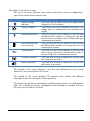
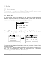
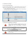
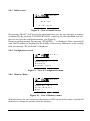
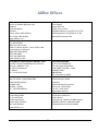
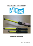
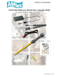
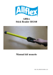
AFX-100 Reader User Manual EID_UM_1000109_AFX100M1.6_US EID_UM_1000109_AFX100M1.6_US 2 1 INTRODUCTION The AFX-100 Reader is a portable reader for RFID tags with the purpose of identifying animals. The device is fully compliant with ISO standards ISO11784 and ISO11785 and with the FDX-A (Destron Fecava version, Trovan technologies and Avid’s encrypted technology), FDX-B, and HDX technologies. The reader can also capture the temperature information with Allflex TD implants and Destron Fearing BT implants. In addition to its tag reading functions, the AFX-100 Reader can store up to 1800 IDs, each associated with a time/date stamp, in its internal memory and transmit them to a personal computer via an USB interface or an optional Bluetooth® interface. Using the device is easy and a clear menu gives several options to personally configure your reader. Features Unique dual element omnidirectional antenna provides improved reading Backlight graphical display Audible beeper and tactile vibrator reading indicators (configurable) Optional Bluetooth® Technology wireless connectivity (factory option) Real-time clock/calendar for time/date stamping tag readings Temperature reading capabilities from temperature detection implants Compact and lightweight profile o 280mm L x 83mm W x 55mm H (11” x 3.3” x 2.2”) o 275 g (9.7 oz.) Rechargeable 700 mAH NiMH battery provides up to 15 hours of use 3 hour fast charge time Battery charge level indicator Automatic shutoff conserves battery life Carrying case for storing AFX-100 Reader and its accessories 3 2 SPECIFICATIONS General Norms: Memory: Battery: Autonomy: Date/Time autonomy: Battery charge duration: Full ISO 11784 and full ISO 11785 including annex C for FDX-A (Destron, Trovan and encrypted Avid), FDX-B and HDX. Temperature scanning with TD and BT implants Graphical display 128x64 dots 2 keys Buzzer and Vibrator USB port and optional Bluetooth® module Serial emulation (CDC class) from 1200bps to 115200bps. Class 2 (up to 10m) Serial Port Profile (SPP). 1800 animal IDs 7.2VDC – 700mAh NiMH rechargeable. 15 hours @ 20°C 1 month without reader using @ 20°C 3 hours Mechanical and physical Dimensions: Weight: Material Color Operating temperature Storage temperature Humidity: 280 x 83 x 55 mm (11 x 3.27 x 2.17 in) 275 g (9.7 oz) ABS-PC Cool Gray 1 -10°C to +40°C (+14°F to +104°F) -30°C to +70°C (-22°F to +158°F) 80% Special feature: User interface: USB interface: Bluetooth® interface: Reading Distance for implants HDX: @ orientation (°) Distance for implants FDX-A Destron (Fecava version) technology: @ orientation (°) Distance for implants FDX-A Trovan technology: @ orientation (°) Distance for implants FDX-A Encrypted technology: @ orientation (°) Distance for implants FDX-B: @ orientation (°) Figure 1 - implants perpendicular to the reader. Up to 16 cm (6.3 in) @ 0° [Figure 1] Up to 10 cm (4 in) @ 90° [Figure 2] Up to 6 cm (2.4 in) @ 0° [Figure 1] Up to 4 cm (1.6 in) @ 90° [Figure 2] Up to 1 cm (0.4 in) @ 0° [Figure 1] Up to 2 cm (0.8 in) @ 90° [Figure 2] Up to 4.5 cm (1.7 in) @ 0° [Figure 1] Up to 2.8 cm (1.1 in) @ 90° [Figure 2] Up to 13 cm (5.1 in) @ 0° [Figure 1] Up to 8 cm (3.15 in) @ 90° [Figure 2] Figure 2 - implants parallel to the reader. 4 3 DESCRIPTION OF DIFFERENT PARTS The Figure 3 below shows all parts included in the packaging. AFX-100 Reader with optional Bluetooth® module. Instruction Guide. 1 x 7.2 Volt DC NiMH rechargeable battery pack. 100 / 240 VAC – 12 VDC wall adapter with plug kit. USB cable. AFX-100 Reader CD-ROM and Bluetooth® CD-ROM. o AFX-100 CD-ROM contains the User Manual, the AFX-100 USB driver, the protocol specifications and the demo software o Bluetooth® CD-ROM contains the driver and the applications related to the USB Bluetooth® key. Wrist strap. Optional car kit. Optional USB Bluetooth® dongle AFX-100 Reader Plug kit Instruction guide Wrist strap Bluetooth key Wall adapter USB cable Figure 3 – AFX-100 Reader Packaging. 2 The Figure 4 shows the charge connector and the USB connector used to connect the reader to a personal computer. Charge connector USB connector Figure 4 - View of the connectors. 3 4 PREPARING FOR USE It is necessary first to fully charge the Battery Pack as described below and to have an few electronic identification eartags or implants available for testing. The battery charge can be realized at a temperature between +10° and +40°C. It is very important to carry out the following three steps before using the AFX-100 Reader. Step 1: Installing the battery pack in the AFX-100 Reader 4 1 Remove the battery cover 2 Connect the battery to the connector 3 Insert the battery and place the wire in the box 4 Refit the cover Step 2: Trickle charging the battery pack. Charge the battery Plug the power cord into the reader, then plug the adapter into a power outlet The battery icon changes to charging starts. and 0 0 : 0 0 1 A L L F L E X A F X - 1 0 0 0 1 / 0 1 / 2 0 0 1 R e a d M e n u The battery icon will be when charging has finished. Charging takes approx. 3 hours. 2 Remove the power cord. Unplug the adapter from the power outlet, then remove the power cord inserted in the reader. 5 Step 3: Activating the AFX-100 Reader and read test READ ZONE 1 Activate the reader Press one button to power-up the reader. After the reader is powered-up – Press the button READ (button under the mention “READ” onto the display) to read an eartag or an implant. 2 Place an implant in the reading zone Typical read o Up to 16 cm (6.3 in) @ 0° (implants parallel to the reader) o Up to 6 cm (2.4 in) @ 0° (implants parallel to the reader) o Up to 13 cm (5.1 in) @ 0° (implants parallel to the reader) 6 5 READER DESCRIPTION 5.1 User interface The user interface comprises a graphical display protected by a transparent window and 2 keys which functions can be inverted by the user. 0 0 : 0 0 ALLFLEX AFX-100 0 1 / 0 1 / 2 0 0 1 R e a d M e n u Configuration / state of the reader. Area for displaying ID numbers, date, menus and messages Key bar with indications about the function of keys located below the screen. Figure 5 – View of user interface. 7 The display is divided in 3 areas: The top of the screen displays icons which represent the current configuration / state of the reader and the current time. Icons Name Battery Charge indicator Charge indicator Bluetooth indicator Bluetooth indicator not connected USB indicator Vibrator indicator Buzzer indicator Description This icon will be used to show the approximate charge level of the battery. This icon will be used to indicate the battery is in charge and it is connected to an external power supply. This icon will be used to indicate to the user that the Bluetooth® module is connected to an host and the device is ready to start a Bluetooth® port communication session. This icon will be used to indicate to the user that the Bluetooth® module is activated but it is not connected to an host. This icon will be used to indicate to the user that the device is connected to an host and is ready to start an USB port communication session. The icon will be used to indicate to the user that the vibrator is activated. The icon will be used to indicate to the user that the buzzer is activated. The bottom of the screen displays a key bar with indications on the current function of key located below the screen. The middle of the screen displays ID numbers, date, menus and different messages for the user during the reader operation. The display has got its own backlight providing good contrast even with ambient light. For reducing the battery consumption, the backlight is switched off if no key entry occurs within 6 seconds. 8 5.2 Reading 5.2.1 Reading antennas The antennas are in the interior part of the reader. The position of the antennas permits to read a transponder possibly oriented in different directions. 5.2.2 Reading tags To read electronic eartags and implants with the AFX-100, press the button that mentions “READ” in the key bar (for example, according to figure below, the user has to press the left button), as a result the screen backlight switches on. 0 0 : 0 0 A L L F L E X A F X - 1 0 0 0 1 / 0 1 / 2 0 0 1 R e a d M e n u When an EID tag or implant is successfully read, the tag's ID code information appears on the LCD readout (see below). The ID code is automatically stored in the reader's internal memory along with the current time and date. 0 0 : 0 0 0 0 : 0 0 250 003541938236 R e a d i n g . . . H D X 1 0 0 0 0 0 0 1 / 0 1 / 2 0 0 1 R e a d M e n u R e a d M e n u The buzzer and the vibrator will sound and/or vibrate with every scan, of course if these options are activated. Every time a tag or implant is scanned, according to the Pet Reader’s configuration (if there is an activated Bluetooth® module), the identification code is transmitted automatically by use of the USB cable / Bluetooth® port. 9 5.2.3 Reading Temperature Detection implants To read TD® implants with the AFX-100, follow instructions described in the previous chapter “5.2.2 - Reading tags”. When an EID TD implant is successfully read, the tag’s ID code information and the temperature measured by the implant appear on the LCD readout (see below). The ID code and the temperature are automatically stored in the reader’s internal memory along with the current time and date. 0 0 : 0 0 0 0 : 0 0 250 003541938236 R e a d i n g . . . 37.5°C 0 1 / 0 1 / 2 0 0 1 R e a d R e a d M e n u M e n u Note 1 – if the temperature measured by the TD implant is below +33°C (+91.4°F), the message “TEMP BELOW RANGE” is displayed and if the temperature is above +43°C (+109.4°F), the message “TEMP ABOVE RANGE” is displayed. Note 2 – the temperature can be displayed in Degrees Celsius or in Degrees Fahrenheit. Note 3 – Wireless synchronization is not activated by default. “A mobile transceiver by nature cannot directly be connected to other transceivers. To prevent a mobile transceiver interfering with the interrogation protocol of other transceivers, it must be able to detect the presence of additional active transceivers through the reception of activation signals. If no activation signal is detected within 30 ms, the transceiver is out of reach of other active transceivers and its activation signal will not interfere with other interrogation processes. The transceiver can therefore safety use the protocols defined in clause 6 of this International Standard. If the mobile transceiver detects an activation signal it must wait for the rising edge of the next activation signal and activate during a fixed period of 50 ms.” (cf. ISO1185 – Annex C chapter 3) Note 4 – Activate the wireless synchronization feature only with readers which complied with the ISO11785 timings. 10 5.3 Pet Reader Power Supply 5.3.1 Power Source Requirements The AFX-100 Reader contains a 7.2VDC – 700mAh NiMH rechargeable battery pack, which serves as its primary power source. Alternately, the pet reader can be powered: From its external wall Adapter/Charger, From its USB cable but it cannot read transponders without a charged battery. The USB connection cannot charge the battery. At the top of the screen, an icon appears indicating the battery’s charge state. Display Summary Good. Quite good. Slightly depleted, but sufficient Depleted. Recharge the battery. “LOW BATTERY” Depleted. Recharge the battery. AC adapter connected and battery charge in progress. Battery charged. 5.3.2 Special notes regarding power requirements Note 5 - The AFX-100 Reader is designed to operate only with the Battery Pack provided. The Pet Reader will not operate with individual battery cells of either disposable or rechargeable variety. CAUTION RISK OF EXPLOSION IF BATTERY IS REPLACED BY AN INCORRECT TYPE. DISPOSE OF USED BATTERIES ACCORDING TO THE INSTRUCTIONS Note 6 - Do not use this apparatus near water when connected to the AC/DC adapter. 11 Note 7 - Do not install near any heat sources such as radiators, heat registers, stoves, or other apparatus (including amplifiers) that produce heat. Note 8 - Unplug this apparatus during lightning storms or when unused for long periods of time. Note 9 - Unplug the wall adapter when the reader is connected to a personal computer by its USB cable. AC Adapter - The AFX-100 Reader can be powered using its AC Adapter/Charger regardless of the charge state of the Battery Pack. The AC Adapter can be used as a power source even if the Battery Pack has been removed from the Pet Reader. If the AC Adapter has been connected, the user may proceed with configuration and performance testing while the Battery Pack is charging. This configuration could affect reading performances. Note 10 - The Pet Reader’s integral Battery Pack is affected by temperature. At 0°C (32°F), the Battery Pack will deliver only about half of its rated energy capacity. At lower temperatures, the Battery Pack may deliver unsatisfactory performance. When the AFX-100 Reader is used in low temperature environments, connection to an external power source is recommended. Note 11 - To ensure proper Battery Pack charging, charging should be conducted only in an environment where the temperature is between 15°C and 30°C (60°F to 85°F). Charging at temperatures outside these boundaries will result in unsatisfactory charge acceptance by the Battery Pack. For more information about the characteristics of rechargeable batteries, please see the white paper at [http://www.national.com/appinfo/power/files/f19.pdf#page=1]. Note 12 – Once the external AC adapter is connected, the reader is powered-up and it will remain on till the AC adapter is disconnected. The reader will be able to read tags. 12 5.4 USB connection 5.4.1 USB cable The AFX-100 reader uses an USB cable to connect the reader to a computer. Once the cable is connected, the icon is displayed. 5.4.2 USB interface The reader is equipped with a mini USB connector on the side of the reader. The USB port can be used to configure the reader (according to ALLFLEX protocol defined in document AFX-100_ProtocolSpecifications.1_1.pdf) and to download the animal ID numbers saved in the internal memory. The communication between the reader and the computer is realized by serial port. Note 13 – Once the USB cable is connected, the reader is activated and it will remain activated up to the cable is disconnected. The reader will be able to read a tag with a sufficient charged battery. With empty battery, the reader stays on and can only communicate with computer. 5.5 Bluetooth® interface Optionally, the reader can be equipped with a Bluetooth module in class 2. This module allows establishing a wireless connection between the reader and a personal computer or PDA. The module is compliant with the Bluetooth® Serial Port Profile (SPP). The connection is automatically set in slave mode once the module is powered on. When the module is enabled, the icon replaced by the icon is displayed and once it is connected the icon is . 5.6 Internal Memory Each ID Code is stored internally in the AFX-100 Reader’s non-volatile memory until the user deliberately erases the stored ID codes after downloading them into a recording device, such as a PC database. Up to 1800 ID codes can be stored and retrieved later at the user’s convenience. 13 5.7 Time stamping The AFX-100 Reader provides a Time Stamping Function that inserts the date and the time for each ID number into the list of ID numbers stored. The user can configure the date and the time through the menu or through communication interface (USB or Bluetooth® port). 5.8 Menus The user can access different configuration options by key navigation. The different options of the menus are displayed in the middle of the screen. The key bar below the menu changes according to each menu and according the keypad configuration (the user can dedicate its keypad either to a left-handed or to a right-handed user). 5.8.1 Screen upon activation (if power-up) To turn on the AFX-100 Reader, only with the battery pack charged and installed, press one of the buttons, the screen backlight will switch on. When the AFX-100 Reader is powered up, the LCD readout appears as shown below: 0 0 : 0 0 A F X - 1 0 0 0 1 / 0 1 / 2 0 0 1 R e a d M e n u Figure 6 – screen at activation. This power-on message indicates that the AFX-100 Reader is ready to read new tags. Note 14 - Once activated, the reader will remain activated for 60 seconds if it is powered only by battery pack. 14 5.8.2 Navigation in the menus The Figure 7 shows menu tree options from the welcome screen. Main screen MENU Memory Status Send All ID’s READ Clear Memory Bluetooth On / Off Search device Cancel Pairing Settings Vibrator Buzzer Keypad Temperature Language Date/Time Reader infos Set Date/ Time Date Format Figure 7 - Navigation tree. Note 15 - The reader automatically closes the menu if no action occurs for 8s. Note 16 – The sub-menu “Bluetooth” is displaying only for the AFX100 with Bluetooth® module. 15 5.8.3 Initial screen 0 0 : 0 0 A F X - 1 0 0 0 1 / 0 1 / 2 0 0 1 R e a d M e n u Figure 8 – View of Initial Screen By pressing “READ” (left key for the right hand user set), the user attempts to capture an animal ID. By pressing “CONFIGURATION” (right key for the right hand user set), the user accesses the configuration menu. (see Figure 9). During a reading attempt, the message “READING…” is displayed. After a successfull read, the ID number is displayed in the middle of the screen. Otherwise, if the reading fails, the message “ID not found” is displayed. 5.8.4 Configuration screen 0 0 : 0 0 M e n u M e m o r y B l u e t o o t h S e t t i n g s R e a d e r i n f o s 6 OK Figure 9 - View of Configuration menu. 5.8.5 Memory Menu 0 0 : 0 0 M e m o r y S t a t u s S e n d C l e a r A l l I D ’ s M e m o r y B a c k 6 OK Figure 10 – View of Memory menu. With this menu, the user can access the numbers of IDs stored in the reader, send the ID numbers to a computer and also clear the memory. 16 5.8.6 Bluetooth Menu 0 0 : 0 0 B l u e t o o t h O n / O f f S e a r c h d e v i c e C a n c e l p a i r i n g B a c k 6 OK Figure 11 – View of Bluetooth® menu. With this menu, the user can: Enable / Disable the Bluetooth® module. Search all Bluetooth® devices to establish a connection. Cancel pairing between reader and external Bluetooth® devices. 5.8.7 Settings Menu 0 0 : 0 0 S e t t i n g s V i b r a t o r B u z z e r K e y p a d T e m p e r a t u r e OK 6 ê Figure 12 – View of Settings menu. With this menu, the user can: Enable / Disable the buzzer and the vibrator. Invert the key functions. Select the temperature measurement unit (Degrees Celsius or Degrees Fahrenheit) and enable/disable the transmission of the temperature measurement by the reader Select the reader language: English, French, Spanish and Portuguese. Configure the date and the time of the reader. 17 5.8.8 Reader infos Menu 0 0 : 0 0 R e a d e r S / N : i n f o s C x x x - y y y y F W : 0 . 5 0 H W : 1 . 0 0 P R : 1 . 0 0 OK Figure 13 – View of Reader Infos menu. With this menu, the user has access to: the serial number of the reader, the software version, the hardware version, and the protocol version. 18 6 USING USB The USB port allows the AFX-100 and the AFX-100 with Bluetooth® module to send and receive data via an USB connection. To make USB operate, you need to connect the reader with a PDA (hand held computer) or a computer. If you are using a PDA or computer you will require a driver (supplied by Allflex). For Windows XP: At the connection of the reader with its USB cable to a computer, Windows starts the device management. Follow the screens below. Select the directory “Drivers CDC/inf” on your CD-DROM drive if Windows is not able to find automatically the driver. 19 For Windows 7: At the connection of the reader with its USB cable to a computer, Windows starts the device management. 20 Open the panel for the peripheral and printer management. Then follow the screens below. Right click on the icon and select “properties”. 21 22 When the installation of the driver is finished, the number of the serial port COM appears after the product name. 23 7 USING BLUETOOTH® The Bluetooth® module allows the AFX-100 with Bluetooth® module to send and receive data “wirelessly” via a Bluetooth® connection. To make Bluetooth® operate, you need to connect the Bluetooth® reader with another Bluetooth® enabled device, like a PDA (hand held computer), a computer, or a Bluetooth® dongle that is attached to a scale head (as shown below). If you are using a PDA or computer you will require software (Not supplied by Allflex). Your software supplier will explain how to connect the PDA, or your computer to the Allflex Reader. Bluetooth® works on a premise that one end of the communications will be a MASTER and the other a SLAVE. The MASTER initiates communications and looks for a SLAVE device it has been connected to. PDAs and computers usually behave as MASTERS. WARNING: When used in the appropriate manner and setup correctly, Bluetooth® offers an excellent method of cable free data transfer. However, Bluetooth® can also be made far too complex by some users. Allflex advises that to achieve successful implementation of Bluetooth® with our AFX-100 reader with Bluetooth® module, users are specifically requested to follow the simple implementation methods listed (following). If these implementation methods are not followed, Allflex cannot guarantee that implementation will not be problematic. This means the Bluetooth® connection may become inconsistent, thus causing other reader related errors. 24 7.1 Bluetooth® – Known Successful Methods There are 2 scenarios to correctly implement Bluetooth®. These are: 1. AFX-100 with Bluetooth® module to a Bluetooth® adapter connected to the USB Bluetooth® dongle or a Bluetooth® enabled PDA (Palm Top Computer/Portable Data Assistant) 2. AFX-100 with Bluetooth® module to a dedicated Bluetooth® device, such as printer. These options are discussed in further details below. 7.1.1 AFX-100 with Bluetooth® module to a Bluetooth® adapter connected to the USB Bluetooth® dongle or a Bluetooth® enabled PDA (Palm Top Computer/Portable Data Assistant) This scenario requires that a process called « Pairing » be undertaken. Start your personal computer (with the USB Bluetooth® dongle) or PDA Bluetooth® services and according the following links, search the reader AFX-100 with Bluetooth® module in the peripheral list and connect it. You have to add an outgoing port that makes a connection to the AFX-100 device with Bluetooth® module. Follow the steps described in the links above. For Windows XP: http://support.microsoft.com/kb/883259/en-us For Windows 7: http://windows.microsoft.com/en-US/windows7/Connect-to-Bluetoothand-other-wireless-or-network-devices Sometimes, a PIN code is required to connect the “AFX-100 with Bluetooth® module” to the PC, PDA… In such case, the PIN code to use is 0000. 7.1.2 AFX-100 with Bluetooth® module to a dedicated Bluetooth® device, such as printer. This scenario requires that the reader lists the Bluetooth® peripherals. Go to the menu “Bluetooth”, then the menu “Search device” which launches the Bluetooth® scanning. Start your personal computer (with the USB Bluetooth® dongle) or PDA Bluetooth® services and according the following links, search the reader AFX-100 with Bluetooth® module in the peripheral list and connect it. You have to add an incoming port that makes a connection to the AFX-100 device with Bluetooth® module. Follow the steps described in the links above. For Windows XP: http://support.microsoft.com/kb/883259/en-us For Windows 7: http://windows.microsoft.com/en-US/windows7/Connect-to-Bluetoothand-other-wireless-or-network-devices Sometimes, a PIN code is required to connect the “AFX-100 with Bluetooth® module” to the PC, PDA… In such case, the PIN code to use is 0000. 25 Regulatory information USA-Federal Communications Commission (FCC) This equipment has been tested and found to comply with the limits for a Class B digital device, pursuant to Part 15 of FCC Rules. These limits are designed to provide reasonable protection against harmful interference in a residential installation. This equipment generates, uses, and can radiate radio frequency energy. If not installed and used in accordance with the instructions, it may cause harmful interference to radio communications. However, there is no guarantee that interference will not occur in a particular installation. If this equipment does cause harmful interference to radio or television reception, which can be determined by tuning the equipment off and on, the user is encouraged to try and correct the interference by one or more of the following measures: Reorient or relocate the receiving antenna. Increase the distance between the equipment and the receiver. Connect the equipment to outlet on a circuit different from that to which the receiver is connected. Consult the dealer or an experienced radio/TV technician for help. The user must be at 20 cm of the reader antennas. Notice to Consumers: Any changes or modifications not expressly approved by the party responsible for compliance could void the user’s authority to operate the equipment. Canada – Industry Canada (IC) This device complies with RSS 210 of Industry Canada. Operation is subject to the following two conditions: (1) this device may not cause interference, and (2) this device must accept any interference, including interference that may cause undesired operation of this device.” L ‘ utilisation de ce dispositif est autorisée seulement aux conditions suivantes : (1) il ne doit pas produire d’interférence et (2) l’utilisateur du dispositif doit être prêt à accepter toute interférence radioélectrique reçu, même si celle-ci est susceptible de compromettre le fonctionnement du dispositif. L’utilisateur doit se tenir à 20 cm des antennes du lecteur. Avis aux consommateurs: Toutes modifications non expressément approuvées par la partie responsable de la conformité peuvent annuler le droit de l'utilisateur à utiliser cet équipement. 26 Regulatory Compliance ISO 11784 & 11785 This device complies with the standards set forward by the International Standardization Organization. Specifically with standards 11784: Radio frequency identification of animals -- Code Structure 11785: Radio frequency identification of animals -- Technical Concept. FCC NQY-30001 IC 4246A-30001 CE Marking Trademark Notices Bluetooth® is a registered trademark of Bluetooth SIG, Inc. 27 28 Allflex Offices Allflex UK Ltd. Unit 6 - 8 Galalaw Business Park HAWICK United Kingdom TD9 8PZ Phone: 44 (0) 1450 364120 Fax: 44 (0) 1450 364121 www.allflex.co.uk Allflex USA, Inc. P.O. Box 612266 2805 East 14th Street Dallas Ft. Worth Airport, Texas 75261-2266 United States of America (800) 989-TAGS [8247] (972) 456-3686 (972) 456-3882/FAX www.allflexusa.com SISTEMAS DE IDENTIFICAÇAO ANIMAL LTDA Rua Dona Francisca 8300 Distrito Industrial Bloco B – Módulos 7 e 8 89.239-270 JOINVILLE SC BRASIL Tel : +55 47 451 05 00 Allflex Europe S. A. ZI DE Plague Route des Eaux 35502 Vitre, France Téléphone/Phone: 33 (0)2 99 75 77 00. Télécopieur/Fax: 33 (0)2 99 75 77 64 www.allflex-europe.com ALLFLEX ARGENTINA CUIT N° 30-70049927-4 Pte. Luis Saenz Peña 2002 1135 CONSTITUCIÓN - CABA BUENOS AIRES ARGENTINA Tel: +54 11 41 16 48 61 Allflex Australia 33-35 Neumann Road Capalaba Queensland 4157 Australia Phone: 61 7 3245 9100 Fax: 61 7 3245 9110 www.allflex.com.au Allflex Canada Corporation Allflex Inc. 4135, Bérard St-Hyacinthe, Québec J2S 8Z8 Canada Téléphone/Phone: (450) 261-8008 Télécopieur/Fax: (450) 261-8028 BEIJING ALLFLEX PLASTIC PRODUCTS SAN TAI SHAN - XIAO HONG MEN CHAO YANG DISTRICT PO BOX 5206 BEIJING – CHINA Tel : +86 10 87606130 Allflex New Zealand Private Bag 11003 17 El Prado Drive Palmerston North Phone: 64 6 3567199 Fax: 64 6 3553421 www.allflex.co.nz 29