1
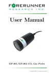
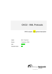
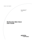
User Manual
GP-001/GP-002 CO2 Gas Probe
c
Copyright 2014.
Forerunner Research Inc.
This guide is distributed by FORERUNNER RESEARCH INC (“Forerunner”) for users
of the GP-001 or GP-002 Gas Probe instruments in conjunction with the FRConnect-GP
software. The GP housing and internal wiring is under warranty by Forerunner to be free
from defects in workmanship and materials under normal use and service for thirty-six
(36) months. The infrared gas analyzer sensor is covered by warranty against malfunction
for twelve (12) months. This warranty shall not apply to any Forerunner products which
have been subjected to misuse, modification, neglect, accidents of nature, or shipping
damage. The GP membrane is not covered under warranty. This membrane will degrade
over time and should be replaced after twelve (12) months. Membrane replacements
are offered by Forerunner for purchase. Forerunner is not liable for special, indirect,
incidental, or consequential damages. Forerunner’s obligation under this warranty is
limited to repairing or replacing (at Forerunner’s discretion) defective products. The
customer shall assume all costs of removing, reinstalling, and shipping defective products
to Forerunner where applicable. Forerunner will return said products by surface carrier
prepaid. This warranty is in lieu of all other warranties, expressed or implied.
DISCLAIMER: Please check the GP CO2 Gas Probe Product page on the Forerunner
website (http://www.forerunnerresearch.ca/GP.php) for the most up-to-date manual.
REV: June 23, 2014
2
GP001/GP002 and FRConnect-GP User Manual
Contents
1 Introduction
2 Hardware
2.1 Overview . . . . . . . . . .
2.2 Membrane Integrity . . . .
2.3 CO2 Measurement . . . .
2.4 Main Power & Data Cable
2.5 Power Connectors . . . . .
2.6 Data Cable . . . . . . . .
4
.
.
.
.
.
.
5
5
5
5
6
7
7
3 FRConnect-GP User Interface
3.1 Setup and Connection . . . . . . . . . . . . . . . . . . . . . . . . . . . .
3.2 Using the Interface . . . . . . . . . . . . . . . . . . . . . . . . . . . . . .
8
8
8
.
.
.
.
.
.
.
.
.
.
.
.
.
.
.
.
.
.
.
.
.
.
.
.
.
.
.
.
.
.
.
.
.
.
.
.
.
.
.
.
.
.
.
.
.
.
.
.
.
.
.
.
.
.
.
.
.
.
.
.
.
.
.
.
.
.
.
.
.
.
.
.
.
.
.
.
.
.
.
.
.
.
.
.
.
.
.
.
.
.
.
.
.
.
.
.
.
.
.
.
.
.
.
.
.
.
.
.
.
.
.
.
.
.
.
.
.
.
.
.
.
.
.
.
.
.
.
.
.
.
.
.
.
.
.
.
.
.
.
.
.
.
.
.
.
.
.
.
.
.
4 Logged Datafiles
10
5 Troubleshooting
11
List of Figures
1
2
3
4
5
6
7
SSC Main Power & Data Cable .
DC+ Power Cable . . . . . . . .
Data Cables . . . . . . . . . . . .
FRConnect-GP Main Window . .
FRConnect-GP Data Options . .
FRConnect-GP Plotting Options
Sample FRConnect-GP data file .
.
.
.
.
.
.
.
.
.
.
.
.
.
.
.
.
.
.
.
.
.
.
.
.
.
.
.
.
.
.
.
.
.
.
.
.
.
.
.
.
.
.
.
.
.
.
.
.
.
.
.
.
.
.
.
.
.
.
.
.
.
.
.
.
.
.
.
.
.
.
.
.
.
.
.
.
.
.
.
.
.
.
.
.
.
.
.
.
.
.
.
.
.
.
.
.
.
.
.
.
.
.
.
.
.
.
.
.
.
.
.
.
.
.
.
.
.
.
.
.
.
.
.
.
.
.
.
.
.
.
.
.
.
.
.
.
.
.
.
.
.
.
.
.
.
.
.
.
.
.
.
.
.
.
6
7
7
8
9
9
10
Scaling for single ended voltage outputs on the GP 001/002 sensors. . . .
6
List of Tables
1
3
1
Introduction
This manual outlines the operation and features of the GP-001/GP-002 Carbon Dioxide (CO2 ) Probes, as well as the included FRConnect-GP software package. Before providing power to the GP please ensure that you read the section on Power Connectors
to avoid any damage to the sensor. We strongly recommended that all users read the
complete manual before use.
The Hardware section explains the physical attributes of the GP and its accessories.
The FRConnect-GP User Interface section explains the software that is used to
communicate with the gas probes in order to record data and adjust logging parameters.
The following Logged Datafiles section explains the structure and formatting of the
datafiles recorded by FRConnect-GP, as well as what each field represents. A Troubleshooting section briefly covers some possible issues that may arise during normal
operation of the software. For further information or assistance, please contact [email protected].
4
2
2.1
Hardware
Overview
The GP sensor housing is constructed using a highly-durable acetal (Polyoxymethylene)
housing, which has many advantages for field-use, such as high abrasion resistance and
low water absorption. The housing is cylindrical with a diameter of 51 mm and a length
of 107 mm (120 mm including the electrical connector).
Forerunner’s NDIR CO2 sensor is exposed to gases through a membrane covering the
face of the GP housing. This membrane allows gas transport to the sensor, but does not
allow any intrusion of liquid water. GP-001 sensors are guaranteed waterproof to 1 m of
water column, whereas GP-002 sensors are waterproof to up to 3 m of water column. The
waterproofing of the sensor requires that users do not open the GP housing.
A tamper-evident seal is placed on the GP housing to prevent intentional or
accidental loosening of the cap. Any tampering with the cap will void the
warranty on the GP and its components.
2.2
Membrane Integrity
The GP membrane is critical to proper operation of the device. The membrane should
always appear uniform in colour and free from visible defects. It is important to periodically check the membrane, as use in field conditions may cause it to tear or otherwise
become defective, and the membrane will degrade naturally over time. Membranes should
be replaced annually for best results, though the membrane life-cycle may be shortened
by exposure to harsh conditions. If the membrane appears to be compromised,
it is critical that the GP not be submerged in water. Contact Forerunner at
1-902-870-5220 or by email at [email protected] for additional information
or to order membrane replacements.
When using the GP to monitor CO2 concentrations in water columns deeper than 1
m, users should both slowly lower the sensor into the water and slowly extract the sensor
after the monitoring period. Rapid submersion/extraction in deep water can cause rapid
pressure changes in the sensor and can compromise the membrane seal, allowing water
to leak into the sensor housing. A submersion/extraction timespan of 15 minutes in 3 m
of water should be sufficient to avoid this problem.
2.3
CO2 Measurement
The GP series of sensors measure gas concentration using non-dispersive infrared (NDIR)
sensing, which correlates light source intensity to a specific gas concentration. The GP001/GP-002 sensors offer a CO2 concentration measurement accuracy of ∼1% of full
scale, with a repeatability of 1% of reading. The GP CO2 concentration readings are
automatically corrected for changes in temperature, and can also be compensated for
changes in atmospheric pressure using the ideal gas law correction:
C∗ = C ×
Pref
Pi
where C is the raw concentration, Pref is the reference pressure (101.35 kPa) and Pi
is the pressure measured in the field (in kPa). This correction is incorporated into the
FRConnect-GP software, but must be applied by the user for SE voltage concentration
measurements. For applications where high accuracy is important, Forerunner recommends that users periodically check the calibration of their sensors by exposing them to
known concentration standards. This is necessary as NDIR sensors can drift over time due
to natural changes in the electrical and mechanical properties of the NDIR components.
5
2.4
Main Power & Data Cable
The GP-001/GP-002 ships with a
standard 5 m long power and data
cable (SSC) which plugs directly
into the 12-pin socket on the GP
housing. Figure 1 shows the SSC
Power & Data Cable. Ensure that
the notch on the SSC connector is
aligned with the tab on the 12-pin
GP socket, push to seat the connector on to the socket and hand tighten
the connector.
Power is supplied to the GP via
the two pin connector on the oppoFigure 1: SSC Main Power & Data Cable
site end of the SSC. This connector
also has a tab and notch type system to ensure that the user connects power with the correct polarity. The GP may be
powered by supplying a regulated voltage to the sensor via data logger, battery or other
power supply device. Please see the section entitled Power Connectors for more details.
Sensor data, including CO2 concentration and sensor temperature measurements can
be accessed by two methods. The first is by using the 3-pin Data connector on the
SSC, combined with the Data connector cable. The FRConnect-GP software can then be
used to read the data from the sensor (please see the section entitled FRConnect-GP User
Interface for more information on using FRConnect-GP). Alternatively, the sensor output
can be accessed using the single ended (SE) voltage outputs at the end of the SSC. Three
wires provide signals corresponding to low-range CO2 concentration (Purple), high-range
CO2 concentration1 (Gray) and sensor temperature (Blue). All outputs are scaled from
0-5 V, but each voltage signal may correspond to a different range for concentration and
temperature, depending on the sensor calibration. A example of typical values are shown
in Table 1. Please note that the scaling factors will be affected by calibration ranges and
the user should be aware of their sensor specific calibration.
Parameter
Low-range CO2 Concentration
High-range CO2 Concentration
Temperature
Voltage
0-5
0-5
0-5
Range
V
V
V
Actual Range
0→5000 ppm
0→20000 ppm
-20◦ C→50◦ C
Table 1: Scaling for single ended voltage outputs on the GP 001/002 sensors.
The equations below show an example calculation of CO2 concentration from an assumed single ended voltage reading (SEV) of 2 V:
SEV=2 V
2 V/5 V=0.4
0.4*5000 ppm = 2000 ppm
Please note that unless a specific temperature calibration was requested, the range
for temperature is -20◦ C to 50◦ C. Finally, the optional 10 m cable (SLC) has the same
configuration and outputs as the SSC.
1 High-range calibration values available only with optional dual calibration. With single range calibrated devices, Gray
SE wire is auxiliary (e.g. CO2 alarm, CO2 concentration deviation, etc).
6
2.5
Power Connectors
The power supply cable included with
the GP 001/002 sensors allows for powering the sensor using a DC power supply
(DC+).
Figure 2 shows the DC+ external
power cable. The cable includes a 2pin connector for attachment to the
SSC/SLC cables. The opposite end of
the cable has stripped wire ends, to allow for connection to any DC power supply. The black wire should be attached
to the ground terminal of the DC power
device, and the red wire should be attached to the positive terminal. The GP
can operate on DC power ranging from
5-24 V, with 12 V being the standard
Figure 2: DC+ Power Cable
voltage used during calibration and testing. Exceeding 24 V will damage the
GP, please ensure that the voltage is regulated correctly before connecting the power supply to the GP. The power consumption will vary slightly depending upon the supplied
voltage. At the recommended voltage of 12 V, the average draw is ∼30 mA with a peak
of <100 mA, giving an average power draw of ∼0.36 W.
2.6
Data Cable
Communication between FRConnect-GP and a GP-001/GP-002 uses the RS-232 Serial
protocol. The following components may be used to facilitate this interface.
• GP Data/Power Cable (Fig. 1) - (Included ) Used to power a GP-001/GP-002 as well
as provide an RS-232 interface.
• Serial Extension Cable (Fig. 3a)- (Included ) Connects the GP Data cable to a USBSerial converter.
• USB-Serial Converter (Fig. 3b) - (Optional ) Used to create a virtual comport, allowing the GP Data cable to be connected to a computer through a USB port.
(a) Serial Extension Cable
(b) USB-Serial Converter
Figure 3: Data Cables
7
3
FRConnect-GP User Interface
3.1
Setup and Connection
FRConnect-GP requires no installation on the part of the user. Simply download the
file “FRConnect-GP.zip” from the GP CO2 Gas Probe product page on the Forerunner
website (http://www.forerunnerresearch.ca/GP.php) and save to a suitable directory on
the PC in question; then, unzip2 the file (which contains one folder titled “FRConnectGP”). None of the files in this folder should be removed or changed in any way. If this
occurs, simply remove the entire folder from your PC and re-extract from the zip file to
recreate the folder.
The program executable is labeled “FRConnect-GP.exe”3 , and double clicking this
icon or a Desktop Shortcut will launch the program. It is recommended that you connect
the USB data cable to your computer prior to launching FRConnect-GP; however
you may also refresh the program from the Options menu. The port on which the GP is
connected will likely be the only choice available (Options⇒ComPort⇒COM#), however
you may have to refer to the device manager if several serial port devices are connected
to the computer. Once the port is selected, a connection to the gas probe will be created.
3.2
Using the Interface
Figure 4 shows the FRConnectGP interface. The interface
has three main areas: the logging options; the current reading and start/stop controls; and
the plotting area.
The top
section shows the currently selected datafile/frequency and
the specified external pressure
value (used to correct gas concentrations). These settings can
be modified via the change buttons situated on the right, or
from the menubar.
The middle section shows
the current CO2 concentration
reading, and allows the user to
start and stop logging/plotting.
It also shows how long the current logging session has been
running. Clicking the Start
button will enable FRConnectGP to start collecting measureFigure 4: FRConnect-GP Main Window
ments from a connected GP-001
or GP-002, and to both plot and log this data. Note that the plot will show every individual measurement, while the datafile will contain averages over an interval specified by the
user. Once a session has been started, clicking the Stop button will stop FRConnect-GP
from recording measurements from the gas probe. The plotted values will remain until
the Start button is used again, at which point the plot will be reset.
2 If
your computer lacks decompression software, 7zip is a suitable free utility for handing archive files
computer may be set to hide the .exe extension
3 Your
8
The bottom section contains a plot of recent concentrations over the chosen time
interval. This interval defaults to 15 minutes, but can be changed using the radio buttons at the bottom. If the collected data exceeds this interval, then only the most
recent points will be shown. There are several secondary plotting options available in
Options⇒Plotting Options, including the ability to toggle between an automatic and
fixed scale for the Y-axis.
To start collecting data, first
choose a location to save logged
data by clicking the Change
button across from the “Logging to:” line, or by choosing
File⇒New Log File. Select or
create a CSV file using the Open
File window. Please note that if
the selected file already exists,
new data will be appended at
the end of the file with a new
Figure 5: FRConnect-GP Data Options
header line. Once you have chosen a save file the Data Options window will appear. Choose the desired formatting
options and which fields to log from the Data Options window as shown in Figure 5.
For GP units equipped with the optional
dual range calibration, the range can be toggled
from the Options⇒Plotting Options window
as shown in Figure 6. To plot data using the
high calibration range check the box next to ”Use
High-Concentration Calibration?”
Click the Start button to begin logging data.
In addition to being stored in the selected file,
a plot of the CO2 concentration measurements is
shown in the FRConnect-GP window.
Figure 6: FRConnect-GP Plotting Options
9
4
Logged Datafiles
The measurement data file is formatted as a comma separated values file (.csv) by
default, allowing for easy importing into spreadsheet or plotting software.
Figure 7: Sample FRConnect-GP data file
Each of the possible data fields in the output file are listed below, with a brief description of what that value represents.
Timestamp
The timestamp for the line of data. The default format is
“MM/DD/YYYY HH:MM:SS”, with the option of changing to seconds since start of session.
CO2 Low
The average CO2 concentration over the interval using the lowrange calibration (ppm).
CO2 Low SD
The standard deviation of CO2 Low during the interval (ppm).
CO2 High
The average CO2 concentration over the interval using the highrange calibration (ppm).
CO2 High SD
The standard deviation of CO2 High during the interval (ppm).
CO2 Low Raw
The average CO2 concentration over the interval using the lowrange calibration ignoring user corrections (ppm).
CO2 Low Raw SD
The standard deviation of CO2 Low Raw during the interval
(ppm).
CO2 High Raw
The average CO2 concentration over the interval using the highrange calibration ignoring user corrections (ppm).
CO2 High Raw SD
The standard deviation of CO2 High Raw during the interval
(ppm).
Temp
The average temperature over the interval (◦ C).
Temp SD
The standard deviation of temperatures measured during the interval (◦ C).
Samples
The number of samples that occurred during the interval.
10
5
Troubleshooting
This section provides a few example problems that may occur during use, and the
appropriate action that should be taken to resolve the issue. For these issues as well as
any others that arise, please contact Forerunner Research Inc. at 1-902-870-5220, or by
emailing us at [email protected].
• The GP does not seem to be outputting serial data (using FRConnect-GP)
or SE voltages
Please ensure that the power supplied to the GP is between 5 and 24 VDC.
• FRConnect-GP does not show or log any data.
Ensure that the gas probe is connected to power and that a session has been started
(via the Start button in FRConnect-GP). Check that the correct ComPort has been
selected under Options⇒ComPort. If the problem persists, exit FRConnect-GP, disconnect and then reconnect the USB data cable, then re-launch FRConnect-GP.
• No ComPorts show up under Options⇒ComPort
Ensure that the gas probe is connected to power. Open the device manager from the
Control Panel in Windows and reconnect the USB data cable. If no connections show
up under Ports (Com & LPT), please contact Forerunner for further instruction.
• The GP socket/cable is oxidizing/discolouring when used in water
In environments which have higher than normal levels of salt or other ions, the GP
socket and/or cable may oxidize or discolour. This will not affect the measurement
performance, but will shorten the lifetime of the sensor. In these types of environments
we recommend attaching the cable to the GP probe and then lightly coating the metal
components with silicone grease (i.e. high-vacuum grease). Coating with silicone grease
is also advisable in waterlogged soils.
• S.E. voltage outputs vary with power supply type/voltage
The S.E. voltage wires output 0 V to 5 V signals that correspond to the current CO2 and
temperature readings in the sensor. These outputs can be monitored as an alternative
to receiving digital data. If the GP is powered independently of the device which is
logging the S.E. voltages, then the S.E. voltage may change with varying power supplies
even if the gas concentration or temperature has not changed. It is critical that the
device which is logging the S.E. voltages and that providing the power for the GP have
the same ground. For example if using a commercially available data logger to log the
S.E. voltage, also use the 12 V power supply port that exists on the data logger.
• GP readings are abnormally noisy
The GP sensor requires a stable power supply with minimal noise in order to achieve the
lowest possible noise on concentration and temperature measurements. When using the
GP, ensure that the power supply is of high quality or that the power supply variation
is buffered with an in-line battery or other power smoothing device. If you are unsure
about your power supply setup please contact Forerunner.
• GP readings are off from my laboratory standard
Forerunner makes all efforts to ensure accurate calibration, including periodic checks
against NIST traceable standards, however calibrations may vary from individual laboratory standards. There are several reasons for this, including long term sensor drift,
changes in atmospheric pressure (sensors are calibrated at sea-level) and variation in
gas supplier analysis techniques. We highly recommend that users concerned with
comparing GP results with other laboratory and field instrumentation re-calibrate GP
sensors using the same standards, and/or cross calibrate all instruments.
11
Forerunner Research Inc.
1 Research Drive
Dartmouth, Nova Scotia
Canada, B2Y 4M9
Phone: 1.902.870.5220
Fax: 1.902.466.6889
Email: [email protected]