Transcript
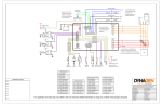
Relay Pak (RP100) Schematic Representation
MOD Bus (RS485)
Common
Relay A
Speed Sensing
(Max 50VAC)
Relay B
J2
J1-6
J1-4
J5
J1939 and RS485 require
120Ω impedance shielded
A
Speed Input is used with
120Ω
120Ω
twisted pair cable.
magnetic pickups, flywheel
Generator
B
Example: Belden 7895A
alternator, or tachometer.
J3
CAN Bus (J1939)
J6
J1-2
Example: Belden 9841
NOT required for generators
J1-2
Shield
Relay C
Relay D
J1-3
J1-1
or electronic engines.
High
J4
120Ω
J7
120Ω
Low
J1-2
J1-2
Max 575VAC
+BAT
A
)+(
+Battery
Ground
)-(
Emergency Stop
Switch Input A
10 9 8 7 6
J6
5 4 3 2 1
Review user manual for
1
more detailed information
2
B
C
on wiring and controller
3
Battery (5.5-36V)
Ground
J4
N
configuration.
Switch Output A
4
8
9
10
11
12
13
14
Switch Output C
Switch Output B
J1
6 5 4
3 2 1
Fuel
1
2
3
4
5
6
7
J7
A
Switch Input B
B
C
N
Switch Input C
Max 5A
Switch Input D
Switch Input E
A
1
Switch Output D
J2
J5
Relay A
N.O. Contact
+BAT
+BAT
Relay Pak (RP100)
J3
J6
Sensor Input B (0 - 750Ω)
Glowplug
Sensor Input C (Universal)
Sensor Input A (0 - 7,500Ω)
B
Relay B
N.O. Contact
Switch Output E
J1
2
C
J3
3
1 2 3 4
5 6 7 8
CT COMMON
4
USB Connection
J5
If current readings are unstable with this
configuration, attempt connecting the CT
Common's to the negative terminal of the battery.
Load
J7
Crank
Relay D
N.O. Contact
Switch Output F
Relay C
N.O. Contact
Ensure the connecting wire is as short as possible.
Sensor Input D (Universal)
J4
Pre-made harnesses are
+BAT
Start / Stop
Contacts
Switched Inputs can be
available. Contact Dynagen
configured to detect
Engine
Temperature
for more information.
Oil
Pressure
Fuel
Level
DC Load
(Max 1A)
Sensor DC Load DC Load
Input (Max 1A) (Max 1A)
battery, ground, or open.
Main Connector
Relay Pak Connector
J4-1
+Battery
J4-2
+Battery
J1-1
Relay D Coil
J4-3
Ground
J1-2
-Battery
J4-4
Ground
J1-3
Relay C Coil
J4-5
Switch Input A
J1-4
Relay B Coil
J4-6
Switch Input B
J1-5
Reserved
J4-7
Switch Input C
J3-1
J1-6
Relay A Coil
J4-8
Switch Output A
J2
Relay A Contact
J4-9
J3
A and C Common
J4
Relay C Contact
J5
J6
Communication Connector
Generator Connector (A)
J6-1
RS485-A
J5-1
Gen. Current (A)
J6-2
RS485-B
J5-2
Gen. Current (B)
Switch Input D
J6-3
Reserved
J5-3
Gen. Current (C)
J3-2
Switch Input E
J6-4
CAN High
J5-4
CT Common
Switch Output C
J3-3
Switch Output D
J6-5
CAN Low
J4-10
Switch Output B
J3-4
Switch Output E
J6-6
CAN Ground
Generator Connector (V)
J4-11
Sensor Ground
J3-5
Switch Output F
J6-7
Speed Input
J7-1
Gen. Phase A
Project Name
Wiring Diagrams
Relay B Contact
J4-12
Sensor Input A
J3-6
Sensor Power (5V)
J6-8
Speed Reference
J7-2
Gen. Phase B
Drawing Name
TG410 Example w/ RP100
Drawing Number
DWG1525
B and D Common
J4-13
Sensor Input B
J3-7
Sensor Ground
J6-9
Reserved
J7-3
Gen. Phase C
DRAWING NOTES
Expansion Connector
NOTE 1:
NOTE 2:
NOTE 3:
NOTE 4:
NOTE 5:
NOTE 6:
J7
Relay D Contact
J4-14
Sensor Input C
J3-8
Sensor Input D
J6-10
RS485 Ground
J7-4
Neutral
NOTE 7:
Your application and wiring may vary. Refer to full user manual for detailed information on using your controller www.dynagen.ca/support.
NOTE 8:
THIS DOCUMENT CONTAINS CONFIDENTIAL INFORMATION AND/OR TRADE SECRETS WHICH ARE THE
PROPERTY OF DYNAGEN TECHNOLOGIES INC. THIS DOCUMENT MAY NOT BE REPRODUCED OR
TRANSMITTED TO OTHERS IN ANY MANNER, NOR MAY ANY USE OF THE INFORMATION ON THIS
DOCUMENT BE MADE, EXCEPT FOR THE SPECIFIC PURPOSES FOR WHICH IT IS TRANSMITTED TO THE
RECIPIENT, WITHOUT THE PRIOR WRITTEN CONSENT OF DYNAGEN TECHNOLOGIES INC.
Drawing Revision
1.4.0
Drawing Scale
Not To Scale
Drawing Size
ANSI-B / Ledger
Created On
12/19/2012
Modified On
01/13/2014
Created By
Everett Pattison
Modified By
Everett Pattison