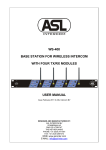
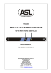
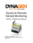
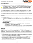
1
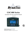
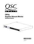
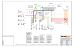
RA400
GSC400 Remote Annunciator
Installation and User Manual – Revision 1.4
Full Version File: MAN-0081R1.4, RA400 User Manual.doc, November 2011
2 of 43
Thank You For Purchasing This DynaGen Product
Please Read Manual Before Installing Unit
Receipt of Shipment and Warranty Return
Information
Upon receipt of shipment, carefully remove the unit from the shipping container
and thoroughly examine the unit for shipping damage. In case of damage,
immediately contact the carrier and request that an inspection report be filed prior
to contacting DynaGen.
All returned items are to be shipped prepaid and include a Return Material
Authorization (RMA) number issued by DynaGen. RMA forms are available by
contacting DynaGen Technical Support through the contact methods listed
below.
Limited Warranty
The RA400 Remote Annunicator carries a one year warranty. For more
information refer to the standard terms and conditions of sale at
http://www.dynagen.ca.
Support
For up to date manuals and other support see http://www.dynagen.ca/support.
We welcome your comments and suggestions. Please contact us at:
DynaGen Technologies Inc.
Phone: 1-888-396-2436
(902) 406-0133
Fax: (902) 567-0633
Email: [email protected]
WEB SITE: www.dynagen.ca
User Manual for the RA400 Remote Annunicator
3 of 43
RA400 Specifications
Uses/Locations
GSC400 Firmware
Requirement
VDC Rating
DC Power
Operating Temp
Annunicators
Intended for indoor, stationary mounting only. Please consult factory for
outdoor or high vibration locations.
GSC400 firmware version 2.00 is required and version 2.03 or latter is
recommended. See installation instructions for more information.
6 to 30 VDC
Min*: 1.3 Watts at 12VDC (109mA), 1.75 Watts at 30VDC (59mA)
Max: 3 Watts (250mA at 12V, 125mA at 24V)
-40°C to +85°C (-40°F to +185°F)
LED Indication
Type
Green
Amber
Red
(Normal)
(Warning)
(Failure)
Overcrank
X
X
Overspeed
X
X
Emergency Stop
X
High Engine
X
X
Temperature
Low Oil Pressure
X
X
Low Coolant Level
X
Low Coolant
Temperature (Low
Engine Temperature)
Low Fuel Level
Communication
Status
Not In Auto
X
X
X
X
X
X
X
High Battery Volts
X
X
Low Battery Volts
X
X
Common Fault
X
X
Low Cranking Volts
X
Battery Charger
X
Failure
User Configurable 1
X
X
User Configurable 2
X
X
System Ready
X
X
Generator Running
X
EPS Supplying Load
X
LEDs will gradually dim when temperature rises above 300C to protect the
LEDs and prolong their life.
Audible Alarm
(buzzer)
Front Panel Button
71 to 86dB at 2ft Typ. Depending on installation, this could be lower.
•
Alarm Silence
•
Lamp Test
Modbus
•
2 wire (simplex)
Communications
•
9600 and 19200 BAUD rates supported
•
Built in terminating resistor (selectable by jumper on board)
•
Isolated
•
Max 2800ft run with Beldin 9841
RS232
•
Firmware updates via RS232
User Inputs
Two digital inputs (16V input maximum, reverse polarity protected)
Dimensions
W x H x D: 203.2 x 203.2 x 38.1 mm (8 x 8 x 1.5 in.)
Weight
0.68 Kg (1.5 Lb)
* Three LEDs Indicators are on in standby: “Communication Status”, “Not In Auto”, and “System Ready”.
The RA400 maintains communication. There is no sleep mode for the RA400.
User Manual for the RA400 Remote Annunicator
4 of 43
Table of Contents
1.
RA400 Remote Annunicator............................................................................... 5
1.1
This Manual....................................................................................................... 5
1.2
Receiving, Handling, and Storage ................................................................. 5
1.3
RA400 Product Number Identification .......................................................... 6
2.
RA400 Series Installation and Wiring ............................................................... 7
2.1
Safety / Information.......................................................................................... 7
2.2
GSC400 Firmware Version............................................................................. 7
2.3
Mounting Location:........................................................................................... 7
2.3.1
RA400 Mounting Dimensions..................................................................... 8
2.4
RA400 Terminals.............................................................................................. 9
2.5
RA400 Parts List............................................................................................. 14
2.6
RA400 Installation Guide .............................................................................. 15
2.6.1
Run Modbus wiring from GSC400 to the RA400. ................................. 15
2.6.2
Wire the GSC400 ....................................................................................... 16
2.6.3
Mount the 8 x 8 x 4” Pull Box ................................................................... 18
2.6.4
Wire the RA400 .......................................................................................... 18
2.6.5
GSC400 Front Panel Configuration ........................................................ 19
2.6.6
RA400 Configuration ................................................................................. 20
3.
RA400 Operation................................................................................................ 22
3.1
Power-up ......................................................................................................... 22
3.2
Reset and Low Power Behavior .................................................................. 22
3.3
Communication Status .................................................................................. 22
3.4
Determining GSC400 Mode from the RA400 ............................................ 22
3.5
RA400 LED Status Indicators ...................................................................... 23
3.6
Alarm (Buzzer) and Alarm Silence .............................................................. 25
3.7
Digital Inputs 1 and 2..................................................................................... 26
4.
Recommended Maintenance ........................................................................... 27
5.
Upgrading RA400 Firmware ............................................................................. 28
Appendix A
Troubleshooting.................................................................................. 33
Appendix B
Modbus Map ....................................................................................... 36
Appendix C
Drawings / Specs ............................................................................... 39
User Manual for the RA400 Remote Annunicator
5 of 43
1. RA400 Remote Annunicator
1.1 This Manual
This manual is divided into two sections:
1. Hardware installation / Configuration
2. Operation
1.2 Receiving, Handling, and Storage
Receiving and Handling:
Every effort is made to ensure that your RA400 Remote Annunicator arrives at
its destination undamaged and ready for installation. The packaging is designed
to protect the RA400 from both electrostatic discharge and mechanical damage.
Care should be taken to protect the equipment from impact at all times. Do not
remove the protective packaging until the equipment is at the installation site
and ready to be installed.
When the RA400 reaches its destination, the customer should inspect the
shipping box and controller for any signs of damage that may have occurred
during transportation. Any damage should be reported to a DynaGen
representative after a thorough inspection has been completed.
A shipping label affixed to the shipping box includes a variety of product and
shipping information, such as items and customer numbers. Make certain that
this information matches your order information.
Each RA400 is packaged in its own box. Do not discard the packing material
until the controller is ready for installation.
Storage:
The packaging is not suitable for outdoor storage. If the RA400 is to be stored
indoors for any period of time, it should be stored with its protective packaging in
place. Protect the remote annunicator at all times from excessive moisture, dirty
conditions, corrosive conditions, and other contaminants. It is strongly
recommended that the package-protected equipment be stored in a climatecontrolled environment of -20 to 65°C (-4 to 149°F), with a relative humidity of
80% or less. Do not stack other equipment on top of the remote annunicator.
User Manual for the RA400 Remote Annunicator
6 of 43
1.3 RA400 Product Number Identification
The RA400 series product numbering scheme (i.e. serial number) provides
various information (including options selection by the customer) about the unit.
A serial number has the format given in Figure 1.
RA400 - _ _ - _ _ _ _ _ - Rev _._ _
Position 1-5
Position 7-8
Position 10-14
Position 19-22
Series
Labeling
Identifier
Revision
Uniquely
indentifies the
particular unit.
Hardware
Revision
Number
Series: RA400
LS=Standard
LX=no label
Figure 1 – RA400 product numbering scheme
User Manual for the RA400 Remote Annunicator
7 of 43
2. RA400 Series Installation and Wiring
2.1 Safety / Information
Generator systems contain high voltage circuitry. Failing to power down and lock
out equipment can cause damage to the equipment, or injury or death to
personnel. The symbols below will be used in this document to classify
information.
Indicates something that you should take special note of
but that is not a threat to safety.
Indicates a potential for injury or death.
This is similar to Danger above but relates specifically to
conditions where high voltage is encountered.
2.2 GSC400 Firmware Version
GSC400 firmware version should be at least 2.00 and above with version 2.03
recommended.
To determine the firmware version cycle power to the GSC400 and observed the screen.
The hardware and firmware versions will display for a few sections before the GSC400
goes into the OFF or AUTO mode.
Note for firmware version 2.00 the default Modbus BAUD rate is set to 57600. This will
have to be changed to 9600 (RA400 default) or 19200 as these are the only two BAUD
rates the RA400 supports.
2.3 Mounting Location:
The RA400 Remote Annunicator must be properly mounted for safe operation.
Caution must be taken at the installation site to make sure the site is free from
condensing humidity, extreme temperature fluctuations beyond -400C to 850C,
and corrosive materials.
Intended for indoor, stationary mounting only. Please consult factory for outdoor
or high vibration mounting locations
User Manual for the RA400 Remote Annunicator
8 of 43
The annunicator is designed to fit in a common 8” x 8” x 4” breakout box – for
example Hoffman ASG8X8X4. Refer to Figure 13 – Hoffman 8x8x4Pull Box on
page 40. Also see Figure 2 – Size and placement of mounting holes below
for the RA400 mounting dimensions.
2.3.1 RA400 Mounting Dimensions
Figure 2 gives the dimensions of the RA400 mounting holes.
Figure 2 – Size and placement of mounting holes
User Manual for the RA400 Remote Annunicator
9 of 43
2.4 RA400 Terminals
The RA400 can be powered from a 12VDC or 24VDC source. It will not
operate below 6VDC and voltages above 30VDC may damage the unit.
All connectors on the RA400 use plug in screw terminals which are included with
the RA400. The installer inserts the wire(s) into the screw terminal, secures the
wire using a flathead screwdriver, and plugs the screw terminal into the terminal
socket on the RA400.
Table 1 on page 11 lists the minimum wire size, maximum current capacity,
name, and function of each circuit. The wire gages given in the table are the
minimum recommended only.
User Manual for the RA400 Remote Annunicator
10 of 43
Modbus 1
Pin 1
Modbus 2
Short Jumper J13
if last device on net
(Default).
Pin 1: NC
Pin 2: A(+)
Pin 3: COM
Pin 4: B(-)
Pin 5: NC
Jumper J13
(2 pin)
Master/Slave: position 1 (OFF =
master, ON = Slave)
BAUD: position 2 (OFF = 9600, ON =
19200)
Device ID: positions 3 to 8 (3 on =
address of 1, 4 on = address of 2)
Default is master, 9600, addr = 1.
Pin 1 Jumper J2
(3pin)
Switch 1
Ensure Pins 1
and 2 are shorted
(Default).
Switch 8
DIP Switch
Programming Port
DB9
User Input 1
Pin 1: Pwr
Pin 2: Gnd
User Input 2
Power EARTH
Pin 1
Pin 1 (+V)
6 – 30VDC, 3W
GND
Figure 3 – RA400 terminals as seen from the rear. Refer to following tables
for more detailed information.
User Manual for the RA400 Remote Annunicator
11 of 43
Table 1 – RA400 Terminal Details
Wire sizes given below are the minimum recommended only. Depending on the length of
the cable run you may require a larger gauge wire.
Power
Wire
Terminal
Terminal
Function
(J14)
Size
#
(AWG)
1
1
18
Main power for the device.
+VDC
COM
2
18
Ground for the device.
Earth
3
18
Chassis or electrical earth. 2
1
Allowable voltage range is +6VDC to +30VDC.
2
Connect this to the chassis of the generator or ground of the
electrical system (preferred).
Modbus
Wire
Terminal
1
Terminal
Size
Function
(J9, J10)
#
(AWG)
NC
1
N/A
Do not connect.
The positive (A) for 2-wire
A (+)
2
24
modbus.
2
Modbus common (ground).
3
24
COM
The negative (B) for 2-wire
B (-)
4
24
modbus.
NC
5
N/A
Do not connect.
1
There are two terminals provided to enable the installer to daisy
chain multiple RA400 units together. If the RA400 is the last
device on the communications bus, the two pins of J13 (the
modbus terminating resister jumper) must be shorted together
(factory default).
2
This must be connected to the GSC400 modbus ground.
User Input
Terminal Terminal
Wire
Max.
Function
1 and 2
#
Size
Voltage (V)
(J4, J5)
(AWG)
Power
1
18
30
Digital input
terminals.
Ground
2
18
N/A*
Apply voltage across the two pins to activate the digital input. The
digital inputs have specific functionality. See section 3.7 Digital
Inputs 1 and 2 on page 26. Reverse polarity protected to 30V.
Damage will occur if the voltage exceeds this.
User Manual for the RA400 Remote Annunicator
12 of 43
Table 2 – RA400 DIP Switch
Eight
Position
Dip
Switch
(SW2)
Switch
1
2
3
4
5
6
7
8
Function
Controls whether the RA400 is a master or slave. OFF
= master, ON = slave. Default is OFF (master).
These control the BAUD rate: OFF = 9600, ON =
19200. Default is OFF (9600).
Switches 3 to 8 are the device ID of the GSC400 unit
connected to the RA400 (if switch 1 is OFF) or the
device ID of the RA400 (if switch 1 is ON).
The device ID can range from 1 to 63. Default is
address 1. See Table 3 to determine the position of
the switches for other addresses.
Note: All DIP switches in the OFF position places the RA-400 in a factory test
mode. To exit this mode move at least one switch to on position and cycle power.
Table 3 – Device ID DIP Switch Position
OFF is indicated by a series of lines. “ON” is used to denote that the switch is in
the “ON” position.
Device ID Switch 3 Switch 4 Switch 5 Switch 6 Switch 7 Switch 8
(x1)
(x2)
(x4)
(x8)
(x16)
(x32)
Software
------------specified.
1
ON
----------2
--ON
--------3
ON
ON
--------4
----ON
------5
ON
--ON
------6
--ON
ON
------7
ON
ON
ON
------8
------ON
----9
ON
----ON
----10
--ON
--ON
----…and so
To determine the position of the switches for device IDs between 10
on, until…
and 28 turn on the switches whose numbers (shown above in
brackets) add up to the device ID). There is a unique combination
for each device ID.
E.g. Device ID 11 = Switch 1, Switch 2, and Switch 4 on = 1 + 2 + 8
= 11, all other switches are off.
60
----ON
ON
ON
ON
61
ON
--ON
ON
ON
ON
62
--ON
ON
ON
ON
ON
63
ON
ON
ON
ON
ON
ON
User Manual for the RA400 Remote Annunicator
Figure 4 – General System Wiring Diagram
14 of 43
2.5 RA400 Parts List
The following table lists the various parts of the RA400 that can be ordered from
either DynaGen or other sources. The DynaGen orderable parts in the table give
the DynaGen Part Number.
Table 4 – RA400 Parts List
Part
Manufacturer
Part Number
DynaGen Part
Number
Power Plug in
Terminal (J14)
On Shore
Technology
Inc
EDZ950/3
N/A
User In 1 / 2
On Shore
Plug in
Technology
EDZ950/2
N/A
Terminal
Inc
(J4, J5)
Modbus 1 / 2
On Shore
Plug in
Technology
EDZ950/5
N/A
Terminal
Inc
(J9, J10)
DB9 serial
MALE - FEMALE (6 FT)
ACC0085
cable
Replacement
N/A
N/A
PCB0048R2.0
Board
DynaGen
GSC400 to
N/A
N/A
DWG1454
RA400
harness
Pull Box
Hoffman
ASE8X8X4
Type 1,
ACC0109
(or equivalent)
(or equivalent)
8x8x4”
AC Power
Mean Well
LPL-18-12
ACC0120
Supply (12V)1
1 Power supply is enclosed (IP64 rating) and rated from -300C to
700C with derating after 500C. See pages 42 and 43 for the
datasheet. Indoor use only.
User Manual for the RA400 Remote Annunicator
15 of 43
2.6 RA400 Installation Guide
This section will step you though the installation and setup of the RA400 to
communicate with the GSC400. While reading the next sections refer to Table 5
and to Table 4 – RA400 Parts List on page 14 for the required/optional parts and
tools.
Table 5 – RA400 Installation Part List
Elec.
Supplier Part
#
Digikey
WM9026-ND
DynaGen
Stock
Code
Ident.
Item
Manufacturer
and Part #
A
Molex Crimper
Molex
63819-0900
B
Modbus 2x3
plug
Molex
39-01-2060
N/A
C
Contacts /
crimps (18-24
AWG)
Molex
39-00-0039
N/A
D
Extraction Tool
Molex
0011030044
E
0.250” wide
Female Quick
Connects
F
G1
Quick Connect
Crimper
Modbus single
twisted pair
shielded cable,
24AWG
Digikey
WM9918-ND
These can be found at your
local electronics parts store.
Belden
9841
N/A
ACC0097
N/A
Use
Crimp contacts for
Modbus Plug
Mating plug for
GSC400 Modbus
Terminal
Contacts crimp on wire.
Allow wire to be
inserted into plug.
Allow wire inserted into
plug to be removed.
Connections to
GSC400 power and
ground spades for
RA400 power.
N/A
Crimp quick connects.
N/A
Modbus A, B, and Gnd
connections between
GSC400 and RA400
Allied Electronics (www.alliedelec.com) P/N: 216-5230
G2
G3
Modbus two
twisted pair
shielded cable,
18AWG power,
20AWG
modbus
Belden
DWG1454
Dynagen
DWG1454
7895A
N/A
N/A
Modbus A, B, and Gnd
connections and power
connections between
GSC400 and RA400.
Limited to 1125ft.
DWG1454
Premade 5ft adapter
cable to plug into
GSC400 with pigtails
on other end.
2.6.1 Run Modbus wiring from GSC400 to the RA400.
The cable for the Modbus A and B connections should be twisted pair cable with
an impedance of 120Ohms (such as G1, G2, and G3). Note the impedance of
the cable is not the same as the resistance of the wires. Check with the cable
manufacturer to ensure you have the proper impedance cable. A third wire is
User Manual for the RA400 Remote Annunicator
16 of 43
needed to connect the modbus ground between the GSC400 and RA400. The
cable drain wire (if using a shielded twisted pair cable) may be used for this
purpose. Each end of the bus must be terminated with 120Ohm resistors.
If you are powering the RA400 from the battery, the wires for the RA400 power
and ground can be run in the same cable (such as G2) as the modbus
communication wires as long as there is no inductive or noisy equipment being
powered from the cable. Noise from the power wires can introduce noise on the
modbus communication wires affecting communications.
Refer to the table in Figure 4 to determine the proper gauge of wire to use for
power and ground.
On the GSC400 end, the cable/wires (G1, G2) can be run from the RA400
directly to the GSC400 (Option A) or run to an intermediate terminal block
(Option B). The installer can order a special harness (G3) from Dynagen or
make their own that runs from the terminal block to the GSC400. The terminal
block must be protected from water (dripping, splash) and accidental shorting.
Since the wires will be exposed it should be also located away from any source
of noise (motors, etc).
More information about the two options can be found in section 2.6.2 below.
2.6.2 Wire the GSC400
Ensure that the generator is disabled before doing any
work on it or the GSC400.
There are two options for terminating the wires on the GSC400 side. The bolded
letters in brackets in the below paragraphs make reference to Table 5.
Modbus Common Note
Older GSC400 LXB / LSB units have an internal 100Ohm resistor between
modbus common and battery -. This may cause damage to the GSC400
modbus transceiver in some applications. It is recommended to run a jumper
from modbus common to battery negative on the GSC400.
To determine if this resistor is in your unit disconnect the modbus cable from the
GSC400 and measure resistance from modbus ground (common) on the
GSC400 modbus terminal (pin 2) to the GSC400 battery negative terminal. If it
reads 100Ohms then your unit has the resistor.
User Manual for the RA400 Remote Annunicator
17 of 43
Option A (Direct Run)
Use this option for best reliability and best immunity to noisy environments.
The installer obtains the individual connectors and installs them on the
cable/wires. The installer would then insert the connectors into the appropriate
GSC400 terminals.
1. Modbus Termination
a. Crimp the contacts (C) onto the three wires for modbus A, B, and ground.
b. Insert these wires into the plug (B). Refer to Figure 4 on page 13 for the
modbus terminal pin out.
c. If you accidently insert the wrong wire into the connector you can use the
extraction tool (D) to remove the wire.
2. Power and Ground Termination (optional)
a. Crimp 0.250” quick connects (E) with a crimper (F) onto the power and
ground wires.
b. Connect these to the GSC400 Battery + and Battery - terminals. The
GSC400 has an extra one of these terminals for this purpose. If both
Battery + and Battery – terminals are taken run the power and ground
wires directly to the battery.
c. If the GSC400 is the last device on the modbus network add a 120Ohm
resistor near the GSC400.
Option B (Intermediate Terminal Block)
DynaGen sells an accessory harness (DWG1454) that has a 2x3 Molex
connector and power and ground terminals installed. The harness can be run
out to a terminal block and the main cable to the RA400 can be run from this
terminal block. The harness is 5 feet long.
1. Insert the harness 2x3 Molex plug into the GSC400 2x3 modbus terminal.
2. If the GSC400 is not the last device on the modbus network cut the resistor
from the harness. If making your own cable make sure to add the 120Ohm
resistor if the GSC400 is the last device on the network.
3. If you are powering the RA400 from the battery follow this step. Otherwise
wrap the extra power and ground in electrical tape to prevent accidental
shorting.
Plug the power (red wire) and ground (black wire) with the female quick
connects for the RA400 to the extra Battery + and Battery - spades on the
GSC400. If these are not available then run to the battery terminals.
4. Connect the other end (3 or 5 wires) to a terminal block.
User Manual for the RA400 Remote Annunicator
18 of 43
2.6.3 Mount the 8 x 8 x 4” Pull Box
The RA400 is designed to fit in an 8x8x4” screw cover pull box. The RA400
replaces the screw cover and the four mounting holes on the RA400 align with
the cover threads on the pull box.
The modbus A, B, and ground wires as well as the power and ground wires must
be run into the panel. In addition the RA400 has an EARTH connection that
must be connected to the ground of the electrical system.
The next section will detail how to make the connections to the RA400.
2.6.4 Wire the RA400
Refer to Table 1 – RA400 Terminal Details on page 11 when reading this section.
1. Connect the modbus A, B, and ground wires to one of the two five-pin screw
terminals. It does not mater which one but all three wires have to be on the
same connector.
2. If the RA400 is not the last device on the modbus network remove the jumper
from J13.
3. Connect the RA400 EARTH wire – located on the three pin screw terminal,
J14 – to the ground of the electrical system and the Pull Box (if used).
4. There are two options for powering the RA400: locally or remotely (generator
battery). If powered locally without a battery the RA400 will loose power
when the utility power is lost until the generator is running and
supplying power.
Local Power
An AC-DC power supply can be used to power the RA400 from the building’s
electrical system. The RA400 requires at least 6VDC although it is
recommended 9VDC or greater in case of voltage drops or other unforeseen
issues.
A simple two prong AC wall adapter can be used to provide power. It must
be able to supply a minimum of 3 Watts (250mA at 12V, 125mA at 24V).
Dynagen also sells a 12VDC power supply: ACC0120 (indoor use only).
Remote Power
User Manual for the RA400 Remote Annunicator
19 of 43
Connect positive and negative wires from the generator battery. Refer to
Figure 4 on page 13.
2.6.5 GSC400 Front Panel Configuration
The GSC400 must have firmware version 2.00 or higher. Version 2.03 or higher
is preferred. To determine the firmware version cycle power to the GSC400 and
observed the screen. The hardware and firmware versions will display for a few
sections before the GSC400 goes into the OFF or AUTO mode.
For firmware version 2.00 the default are address = 1 and baud rate = 57600.
For firmware version 2.03 or greater the default is address = 1 and baud rate =
9600.
This section assumes the GSC400 front panel menu is being used. The PC
Interface can also be used to configure the GSC400. Note: The GSC400 is a
slave device only and cannot act as a master.
1. Modbus BAUD rate – The RA400 can only support 9600 (default) and 19200.
Set the BAUD rate in the Advanced Menu>Set Modbus>Baud Rate to
either of these values.
2. Modbus Device ID – The RA400 can support slave address in the range of 1
(default) to 63 except addresses 2 to 4 which are reserved for slave RA400
units. Set the address of the GSC400 to the desired value in the Advanced
Menu>Set Modbus>Device Address menu.
User Manual for the RA400 Remote Annunicator
20 of 43
2.6.6 RA400 Configuration
After making changes to the configuration switch located on the back of
the RA400 you must cycle the power to the RA400.
Power off the RA400, wait one second, and then power on the RA400.
The RA400 can operate as either a master or slave device. If the GSC400 is
the only other modbus device on your network you need to configure the
RA400 as a master. If you wish to have multiple RA400s on the same network
configure one as a master and the others (up to three) as slaves. The three
slaves must have a modbus address of 2, 3, or 4. The GSC400 can be set to an
address of 1 or to an address between 6 and 63 on the master RA400.
Follow the instructions below to configure each RA400.
RA400 Master Mode
Ensure there are no devices using address 2, 3,
or 4 except RA400 slaves. The RA400 master unit reserves these for
slave RA400s. Placing other devices at these addresses can cause
unexpected results, possible damage to equipment and/or harm to
personnel.
With the RA400 in master mode, it will send requests to the GSC400 for
GSC400 status updates. The RA400 will then turn on or off its indicators
and buzzer as required. It will also send the status updates to addresses
2, 3, and 4 for the RA400 slaves.
1. Set switch 1 of SW2 to the OFF position to set RA400 as master.
2. Set switch 2 of SW2 to either the OFF position for 9600BPS or to the
ON position for 19200BPS. This should match what was set in the
GSC400 front panel menu and those of the slaves.
3. On SW2 set DIP switches 3 to 8 to set the modbus device ID (modbus
address) of the GSC400. This should match what was set in the
GSC400 front panel menu.
RA400 Slave Mode
1. Set switch 1 of SW2 to the ON position to set RA400 as slave.
2. Set switch 2 of SW2 to either the OFF position for 9600BPS or to the
ON position for 19200BPS.
3. On SW2 set DIP switches 3 to 8 to set the modbus device ID (modbus
address) of this RA400.
User Manual for the RA400 Remote Annunicator
21 of 43
Final Setup
1. Reset power to the RA400 by unplugging the three-pin screw-terminal
connector, wait one to two seconds and plug in the connector again. OR
Press the push button on the back of the RA400 (not the button on the
front).
2. The RA400 should go though a lamp test (red flash, then green flash) and
sound the buzzer. If this does not occur the unit may be defective.
Contact DynaGen for further information.
3. The Communication Status indicator should be green. This indicates
that the RA400 has established or is trying to establish communications
with the GSC400. Wait for 8 seconds after power up to ensure
communication is established.
If the Communication Status LED is flashing red then the RA400 could not
establish communications with the GSC400. Try the following:
1. If using the Dynagen supplied harness (DWG1454), connect
the RA400 directly to the end of the harness. If the RA400
works in this case then it may be a wiring issue.
2. Check the firmware version on the GSC400. Requires
firmware version 2.00 or latter. RA400 will communicate
with GSC400 with firmware version 1.38 or latter but not all
lamp indications will work or work properly.
3. Ensure that the modbus A and B connections are not
reversed on the GSC400 and RA400. Ensure that the
modbus ground is connected to the RA400 modbus
connector and the GSC400 modbus connector. Refer to
Figure 4 on page 13.
4. Ensure the BAUD rate is the same on all slaves and master
RA400 units and in the GSC400 front panel menu.
5. If a slave, ensure that the modbus device address is set to
an address of 2, 3, or 4.
6. If a master, ensure the GSC400 device address (switches 3
to 8) on the master RA400 is set correctly and that it
matches that in the front panel of the GSC400.
User Manual for the RA400 Remote Annunicator
22 of 43
3. RA400 Operation
This section explains the operation of the RA400 from a day to day user
perspective.
3.1 Power-up
On power-up, the annunicator will emit a short beep from the buzzer, and then
enter a lamp test. During the lamp test, all red LEDs will be on for 2 seconds,
and then all green LEDs will be on for 2 seconds. Note that the amber color is
produced by a combination of the green and red LEDs.
After lamp test concludes, all of the front panel LED indicators will turn OFF. The
Communication Status LED indicator will then turn green and the annunicator
panel will attempt to establish communication. If communication is unsuccessful,
after approximately 7-8 seconds the Communication Status indicator will flash
red and the buzzer will sound.
3.2 Reset and Low Power Behavior
If the voltage powering the RA400 drops below 6V the microcontroller on the
RA400 will reset but the LED drivers which control the LEDs may not. To the
user it would appear that the RA400 is operational when it is in fact not.
Once the voltage rises to 6V again the RA400 will perform an LED test and
sound the buzzer as it normally does when power is applied.
3.3 Communication Status
In master mode after 7.5s of no communication with the GSC400, the RA400 will
sound the alarm, turn off all LED indicators, and turn the “Communication Status”
LED indicator flashing red.
3.4 Determining GSC400 Mode from the RA400
The GSC400 controller has three main modes of operation: OFF, AUTO, and
RUNNINNG. You can tell what mode the GSC400 is in by looking at the Not In
Auto and Generator Running Indicators on the RA400.
OFF Mode – The Not In Auto Indicator will be red and the alarm will sound
unless it was silenced.
User Manual for the RA400 Remote Annunicator
23 of 43
AUTO Mode – The Not In Auto indicator will be green and the Generator
Running Indicator will be off.
Generator is in delay to start, preheating, cranking, and crank rest – The
Generator Running Indicator will be flashing green.
RUNNING Mode – The “Generator Running” Indicator will be green.
3.5 RA400 LED Status Indicators
The RA400 Indicators will gradually dim when temperature rises above
300C to protect the indicators and prolong their life. This will not be
noticeable unless the ambient temperate is very high.
The master RA400 continuously reads the GSC400 and sends updates to the
slave RA400 units in addition to updating its own indicators. The RA400 units
should respond within two to three seconds of a change in the GSC400 status.
If using a DynaLink device it could take up to 30 seconds for the RA400 units
to update after a change in the GSC400 status especially if a user is viewing data
from the DynaLink device on a web browser.
The DynaLink device is purchased separately and allows the user the ability to
monitor GSC400 data over Ethernet or dial-up. Refer to the DynaLink user
manual for more information.
LED indicators will be illuminated on the RA400 depending upon the condition of
the slave GSC400. The colors of the LED indicators represent the following
unless otherwise specified:
Green
- Represents Normal/Active Conditions
Amber
- Represents Warning Conditions
Red
- Represents Failure Conditions
A lamp test can be performed by holding down the “Alarm Silence” button for a
period of 3 seconds. During the lamp test, all red LEDs will be on for 2 seconds,
User Manual for the RA400 Remote Annunicator
24 of 43
and then all green LEDs will be on for 2 seconds. Note that the amber color is
produced by a combination of the green and red LEDs.
Table 6 lists the LED indicators on the RA400, their definition, and colors.
Table 6 – Front Panel LED Indicators
LED Description
Over Crank
Over Speed
Alarm
Status
ON
ON
Emergency Stop
ON
High Engine
Temperature
ON
Low Oil
Pressure
Low Coolant
Level (Aux)
Low Coolant
Temperature
Low Fuel Level
ON
Solid Red - Failure condition.
ON
Solid Amber - Warning condition.
Note: This is called Low Engine Temperature on the
GSC400.
Solid Red / Solid Amber - Failure / Warning
condition.
Flashing Red - no communication with GSC400
(takes up to 8 seconds to transition from green to
red).
Solid Green - communication with GSC400 ok
Solid Red - GSC400 is in the OFF mode. Automatic
start is disabled.
Solid Green – GSC400 is in the AUTO mode.
Solid Red / Solid Amber - Failure / Warning
condition.
Solid Red / Solid Amber - Failure / Warning
condition.
Flashing Amber – Event condition.
Solid Amber – Warning condition.
Solid Red – Failure condition.
Check the GSC400 for programmed events.
ON
ON
OFF
ON
Not In Auto
OFF
Common Fault
Solid Red - Failure condition on the final crank
attempt.
Solid Amber - Warning condition which occurs after
the first unsuccessful starting attempt when there are
crank attempts still remaining.
Solid Red / Solid Amber - Failure / Warning
condition.
Solid Red - Emergency Stop Active.
Solid Red / Solid Amber - Failure / Warning
condition. Also used to indicate Low Engine
Temperature Shorted or Open sender warning/failure.
Solid Red / Solid Amber - Failure / Warning
condition.
ON
Communication
Status
High Battery
Volts
Low Battery
Volts
LED Status / Description
ON/OFF
ON/OFF
OFF
ON
ON
User Manual for the RA400 Remote Annunicator
25 of 43
Common Fault Indicator uses the Common Fault 1
feature of the GSC400. With this feature you can set
single or multiple failures, warnings, and/or events to
trigger this indictor.
Low Cranking
Volts
OFF
Solid Amber – Warning condition.
ON
Solid Red - Failure condition.
Battery
Charge Failure
ON
OFF
Configurable
Indicator 1
Configurable Indicator 1 uses the GSC400 Config
Warn 1 and Config Fail 1 configurable switched
input features. Configurable Indicator 2 uses the
GSC400 Config Warn 2 and Config Fail 2
configurable switched input features.
Configurable
Indicator 2
System Ready
Generator
Running
EPS Supplying
Load
Battery Charge Failure is lit if either or both of the
GSC400 Charger 1 Fault or Charger 2 Fault
configurable switched input features are active.
Solid Red – Failure condition
Solid Amber – Warning condition
OFF
OFF
OFF
Configurable Indicators 1 and 2 each have a white
area on the label for writing the desired text.
Configurable Indicator 1 is above Configurable
Indicator 2. Use any permanent marker with an ultra
fine tip or a fine tip.
Solid Green / Solid Red – System Ready / System
Not Ready.
Flashing Green – Generator is preparing to run.
Solid Green – Generator is running.
Solid Green – EPS is supplying load.
3.6 Alarm (Buzzer) and Alarm Silence
The alarm may sound when one or more of the LED indictors are lit. Refer to
Table 6 to determine under which events the alarm will be triggered. The alarm
will remain on until the indicator or indictors that caused the alarm are
deactivated or the Alarm Silence button is pressed.
The alarm can be silenced by pressing the “Alarm Silence” button. To re-activate
the alarm (assuming that the event that caused the alarm is still active) press and
hold the “Alarm Silence” button for 3 seconds until a lamp test is performed.
After the lamp test the buzzer will be re-activated for alarming.
User Manual for the RA400 Remote Annunicator
26 of 43
3.7 Digital Inputs 1 and 2
The digital inputs on the RA400 have the following functionality if triggered (you
will need to know which mode the GSC400 is currently in, refer to section 3.4):
Note: only a master RA400 unit has the following functionality. The digital inputs
on slave RA400 units are ignored.
If a local start was performed (Start button pressed on GSC400) then the
generator can only be shutdown by triggering an OFF command from the RA400.
1. If Digital Input 1 is triggered.
If GSC400 is in any mode except OFF (System Disable) – will place the
GSC400 in the OFF mode if it is in any state other than the OFF mode –
including the RUNNING mode. If the GSC400 is running, the controller
will shutdown normally except it will cancel any cool down period if cool
down is enabled.
If GSC400 is in OFF mode (System Enable) – will place the GSC400 in
the AUTO mode if the GSC400 is currently in the OFF mode.
2. If Digital Input 2 is triggered.
If GSC400 is in AUTO mode (Start) – will start the generator if the
GSC400 is in the AUTO mode.
If GSC400 is in RUNNING mode (Stop) – will stop the generator if the
GSC400 is in the RUNNING mode. This includes going though any cool
down period if enabled.
Activating digital input 2 in any other state other than RUNNING and
AUTO will have no effect.
Only one digital input can be activated at any one time. Each digital input must
be active for at least 0.5 seconds before the functionality outlined above is
triggered. After a trigger, neither digital input can be triggered again for at least
0.5 seconds. These features are to prevent accidental triggering. There may be
a delay between input activation and the resulting GSC400 action because
the RA400 must communicate the action to the GSC400.
A digital input is triggered by applying 5V or greater between its power and
ground connections. See Figure 4 – General System Wiring Diagram on page
13 for the location of the digital input connectors.
User Manual for the RA400 Remote Annunicator
27 of 43
4. Recommended Maintenance
The actions in Table 7 should be performed routinely.
Table 7 – Recommended Maintenance
Procedure
Action
Inspect annunciator mounting location
for possible safety issues
Inspect mounting location for any
safety or fire issues. Inspect for dirt,
wiring
damage
and
mechanical
damages.
Inspect annunciator for loose fasteners, Check all hardware including
terminals and wiring connections.
annunciator wiring, terminals etc. for
any looseness due to vibrations etc.
Clean area around annunciator
Periodically inspect and remove any
debris/dirt from within or near the
annunciator.
Check for any overheating due to loose Check for any discoloration, melting or
connections
blistering of any wiring or connections
Perform regular testing of annunciator
Perform regular testing of the
annunciator to check for proper
operation.
User Manual for the RA400 Remote Annunicator
28 of 43
5. Upgrading RA400 Firmware
DynaGen may, from time to time, change the software on the RA400 (i.e.
firmware) to fix bugs, improve performance, or add features. The RA400
provides the user with the capability of easily upgrading the firmware with a DB9
serial cable.
Follow the below steps to load new firmware on the RA400. You will need the
HC08SPRG.exe program.
It is recommended that once the software has been updated that the
software revision be marked on the RA400 for future reference.
1. Remove power from the RA400.
a) Connect one end of the DB9 serial cable with DB9 COM port to the PC
b) Connect the other end of the cable to the DP9 RS232 connector on the
RA400.
c) Move the jumper on J2 over to the left side as outlined by the red circle in
the figure below.
Figure 5 – Reset switch and jumper location.
2. Place the firmware file (will have file extension .S19) and hc08sprg.exe in the
same directory.
User Manual for the RA400 Remote Annunicator
29 of 43
3. Check which COM port the cable is plugged into on your computer, the
HC08SPRG.exe program will need the COM port number of the PC. If you
are using a serial to USB adapter follow these steps (this is for Windows XP):
a) Right click on my computer in the start menu and click properties. The
“System Properties” Window will open.
b) Click on the “Device Manager” button. Another window, called “Device
Manager” will open.
c) Scroll down the window to “Ports (COM & LPT)” If you do not see this,
make sure the USB adapter is plugged in and that the driver was
installed. This option will not show if there are no COM ports on your
computer and the USB to serial adapter is not detected.
d) Click on the “plus” sign next to the “Ports (COM & LPT)”. You should see
the COM port that your adapter uses appear. This is the COM port you
will use below.
4. Use the PC “command prompt” mode (In WINDOWS XP start menu, run
“CMD”, the PC will open a “command prompt” window, also know as DOS).
5. You will need to either store the two files (see step 1) in the current directory
or use CHDIR to change the current directory to the directory folder
containing these two files. In the figure below the current directory is
“C:\Documents and Settings\wmanning”.
Figure 6 – DOS screen
To use CHDIR to change the current directory, type CHDIR and then one space
and then the file directory enclosed in quotations. In the figure below the current
directory was changed from “C:\Documents and Settings\wmanning” to
“C:\Documents and Settings\wmanning\Desktop”.
User Manual for the RA400 Remote Annunicator
30 of 43
Figure 7 – DOS CHDIR command
6. Once you are in the directory that the files were placed, type the command
hc08sprg 1:D 9600 xxx.s19
where:
a) The “1” refers to the COM port of the computer where you obtained in
step 3 above.
b) The 9600 is the BAUD rate of the RA400. Ensure that switch 2 of the 8
position DIP switch SW2 on the RA400 (see Table 2 on page 12) is in the
OFF position.
c) The “xxx” of “xxx.s19” is the name of the firmware .s19 file you have.
7. Press enter. You will see the following info appear if you entered everything
correctly. Note: The numbers may not be the same.
Figure 8 – Valid command response
Otherwise you will see this info.
User Manual for the RA400 Remote Annunicator
31 of 43
Figure 9 – Invalid command response
8. Power on the RA400. You will see the following info appear (numbers shown
may not be the same).
Figure 10 – Program part prompt.
9. Type “y” if you want to start programming or type “n” if you want to cancel.
Then presses the “ENTER” key; the firmware will start to load. A new line will
appear with the percent of memory programmed so far. When this reaches
100% the programmer is finished.
Figure 11 – Programmer status.
User Manual for the RA400 Remote Annunicator
32 of 43
10. The program will verify that the memory has been programmed properly. It
should say OK next to “Memory verified”. If it does not, try programming
again.
Figure 12 – Programmer ok.
11. Place the J2 jumper back in its original place.
User Manual for the RA400 Remote Annunicator
33 of 43
Appendix A Troubleshooting
1. The RA400 appears to be operational (indicators are lit) but does not
respond.
Check that the voltage to the RA400 power inputs is 6V or above. Voltages
between 4.5V and 6V may cause the computer on the RA400 to reset but not
the drivers controlling the LED indicators. This has the effect of making the
RA400 appear operational, when in fact it is not.
2. The RA400 LED Indicators appear dimmer than usual.
The RA400 LED feature protection which decreases the current to the LED
indicators with increase in ambient temperature. This protects the LED and
increases its life. The user should not notice the indicators diming until the
temperature is above 400C to 500C.
If the LEDs are dimmer than usual there could be a problem causing heat
buildup behind the RA400. Remove the RA400 and check all connections. If
it continues the RA400 could be defective.
3. The RA400 appears dead. No indicators are on.
(1) Confirm that power and ground are connected properly. Measure on the
three pin power terminal to ensure at least 6VDC is at the terminal in the
proper polarity. Refer to Figure 3 – RA400 terminals as seen from the
rear. on page 10.
(2) Press and hold the Alarm Silence button for 3-4 seconds. Does the
RA400 perform a lamp test? The indicators should flash green and then
red. If none of them flash or only some of them you may have a defective
unit. Contact DynaGen Technical Support for further information.
4. The Communication Status LED is flashing red.
(1) Check that the firmware in the GSC400 is 2.00 or greater. To do this
cycle the power to the GSC400 and observe the firmware version on
power up.
(2) Ensure that you have the modbus A, B, and ground connections to the
GSC400 and RA400 correct. As a quick test try reversing the A and B
leads on the RA400 side. In addition make sure there is a ground wire
from the GSC400 modbus connector to the RA400 modbus common
terminal.
User Manual for the RA400 Remote Annunicator
34 of 43
(3) Check the baud rate in the GSC400 front panel menu system under
Advanced Menu>Set Modbus and confirm that the DIP switch on the
RA400 is set to the correct BAUD rate. The RA400 can only operate on
two BAUD rates: 9600 and 19200. Refer to Table 2 – RA400 DIP Switch
on page 12 for the switch position meaning.
(4) Check that the RA400 is set to a master. If you are using the DynaLink
WS100/WS200 device on the same modbus network, then the RA400
must be set as a slave and refer to the DynaLink user manual for more
information.
(5) Check that switches 3 to 8 are set correctly on the RA400 to give the
desired device ID. Check that the GSC400 Device ID under Advanced
Menu>Set Modbus>Device Address match that switches 3 to 8 on the
RA400. Refer to Table 3 – Device ID DIP Switch Position on page 12 to
determine the meaning of the DIP switches.
3. The Genset is starting but the “Generator Running” Indicator on the RA400 is
not flashing green.
Check that the firmware in the GSC400 is 2.00 or greater. To do this cycle
the power to the GSC400 and observe the firmware version on power up.
On the RA400 the Generator Running LED will flash green to indicate that
the genset is starting up (delay to start, cranking, crank rest, etc). If you are
using a DynaLink device the delay between a GSC400 action and the
corresponding RA400 annunciation of that action is much longer than using
an RA400 as a master.
Maximum Response Times:
1. RA400 master: 2-3s
2. WS100/WS200 as master with 1 RA400 (with single RA400
configuration file): 5s
3. WS100/WS200 as master with 1 RA400 (with four RA400
configuration file): 45s
4. WS100/WS200 as master with 4 RA400 (with 4 RA400
configuration file): 30s
5. The Common Fault Indicator is not turning on even though I selected my
Failures/Warnings/Events in the Advanced>Common Faults menu on the
GSC400 front panel and one or more of my Failure/Warning/Event I selected
is active on the GSC400. Communications are fine (Communication Status
Indicator is green).
User Manual for the RA400 Remote Annunicator
35 of 43
(1) The Common Fault Indicator uses the Common Fault 1 feature of the
GSC400. Ensure that you set your Failures/Warnings/Events using “Failure
Table 1”, “Warning Table 1”, and “Events Table 1” menus located under the
Common Faults menu in the Advanced menu of the GSC400 front panel
menu system.
(2) Additionally settings may have been changed with the PC Interface. Open
the GSC400 PC Interface and go to the Faults tab under the GSC400
Update tab. Click the Read Faults button at the bottom to get the
information from the GSC400. Under the Common 1 tab, the Common
Faults, Common Warnings, and Common Events should all be selected in the
Modbus box.
The ones not selected will not be sent over modbus to the RA400. The
purpose of the Modbus selection is to allow control over which event type to
display locally and which type to send remotely over modbus. They all are
selected by default from the factory and can only be changed from the PC
Interface.
User Manual for the RA400 Remote Annunicator
36 of 43
Appendix B Modbus Map
Table 8 – Modbus Register Map
Register
40001 ~
Parameter
Description
Reserved
40002
40003 ~
Each event uses 5bits
40009
b4, b3, b2, b1, b0 where b0 is the least significant bit.
(Read
b0 = The event status (warning or shutdown occurring)
Only)
0 = Not Active, 1 = Active
b2-b1 = The severity of the event
0 = Take No Action,
1 = Warning/Acknowledge
2 = Action Required,
3 = Take Immediate Action (shutdown)
b3 = Alarm Action (indicates if GSC400 is sounding buzzer)
0 = No Audible Alarm, 1 = Sound Audible Alarm
b4 = Warning/Failure Feature Enabled/Disabled
0 = Disabled, 1 = Enabled
The follow conditions will turn off the corresponding LED indicator (unless otherwise stated
below):
1. BIT b0, event status, OR BIT b4, feature enabled/disabled, are equal to 0
2. Bits b2-b1, severity, is 0
40003
Bit b3 controls whether the buzzer (audible alarm) sounds, unless otherwise stated below,
assuming bits b0 and b4 are set, and the b1-2 are not cleared.
bits 4-0 System Ready Indicator (red if event status cleared, green is event set)
bits 9-5 Reserved
bits 14-10 High Engine Temperature Indicator (amber if severity set to 1, red if severity
set to 3, off otherwise)
40004
bits 4-0 Low Oil Pressure Indicator (amber if severity set to 1, red if severity set to 3, off
otherwise)
bits 9-5
Overspeed Indicator (amber if severity set to 1, red if severity set to 3, off
otherwise)
bits 14-10 Emergency Stop Indicator (red if severity set to 3, off otherwise)
40005
bit 4-0 Low Coolant Level/Aux Indicator (red if severity set to 3, off otherwise)
bits 9-5 Low Coolant Temperature Indicator (amber if severity set to 3, off otherwise)
bits 14-10 Low Fuel Level Indicator (amber if severity set to 1, red if severity set to 3, off
otherwise)
40006
bits 4-0 Reserved
bits 9-5 EPS Supplying Load Indicator (green if event status is set, off otherwise)
User Manual for the RA400 Remote Annunicator
37 of 43
bits 14-10 Reserved
40007
bits 4-0 Not In Auto Mode Indicator (green if event status is cleared, red if severity is 3,
off otherwise; event status has priority over the severity)
bits 9-5 Battery Charger Failure Indicator (red if severity is 3, off otherwise)
bits 14-10 Low Battery Volts Indicator (check register 40085 first; amber if severity of 1,
otherwise off)
40008
bits 4-0 High Battery Volts Indicator (check register 40085 first; amber if severity of 1,
otherwise off)
bits 9-5 Low Cranking Volts Indicator (amber if severity is 1, off otherwise)
bits 14-10 Reserved
40009
bits 4-0 Common Fault Indicator (flashing amber if severity is 1, amber if severity is 2, red
if severity is 3, off otherwise)
bits 14-5 Reserved
40010 ~
Reserved
40079
40080
Overcrank
Indicator
(GSC400 Front
If Bit 0 is set Red LED turns on regardless of Bit 1, else if Bit 1 is set
Amber LED turns on, else LED turns OFF if both bits are cleared.
Panel LED
Status)
40081
Reserved
~40083
40084
bits 9 and 11 Configurable Indicator 1 (amber if bit 9 set [no audible alarm], red if bit 11
set [audible alarm], off otherwise. If bit 11 is set status of bit 9 should be ignored.)
bits 10 and 12 Configurable Indicator 2 (amber if bit 10 set [no audible alarm], red if bit 12
set [audible alarm], off otherwise. If bit 12 is set status of bit 10 should be ignored.)
Configurable Indicators 1 and 2 each have a white area on the label for writing the desired
text. Configurable Indicator 1 is above Configurable Indicator 2.
If bit9 is set, Low Battery Volts Indicator is red. If bit9 is
40085
High/Low
Battery Volts
Failure Indicator
Override
cleared read register 40007 to determine if indicator should
be amber or off.
If bit 10 is set, High Battery Volts Indicator is red. If bit9 is
cleared, read register 40008 to determine if indicator should
be amber or off.
40086 ~
Reserved
User Manual for the RA400 Remote Annunicator
38 of 43
40099
40100 ~
40101
Generator
Running
Indicator
1. If register 40100 is not equal to 0x9C Indicator is off.
2. If register 40100 = 0x9C and register 40101 = 19, 20,
21, or 23 Indicator is flashing green (preparing to
start).
3. If register 40100 = 0x9C and register 40101 is not
equal to 19, 20, 21, or 23 Indicator is green.
User Manual for the RA400 Remote Annunicator
Appendix C Drawings / Specs
The following pages contain various drawings that may be useful.
Figure 13 – Hoffman 8x8x4Pull Box
Figure 14 – Page 1 of ACC0120 datasheet. Model number is LPL-18-12. Taken from http://www.jameco.com.
Figure 15 – Page 2 of ACC0120 datasheet. Taken from http://www.jameco.com.