1
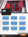
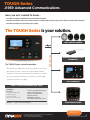
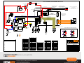
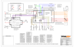
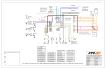
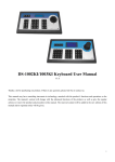
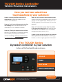
TOUGH Series Controller
Vehicle Mounted Generators
Have you ever been asked these
tough questions by your customers:
How do I receive generator information to
other devices and control modules on the
vehicle’s CAN J1939 bus?
How can I easily control the generator starting
and stopping from a remote location on the
vehicle over its CAN J1939 bus network?
How can I disable the generator from starting
over the CAN J1939 bus? Or simply by sensing
the availability of shore power connection
(vehicle in building)? Were you aware that this
is a requirement in some jurisdictions?
How can I easily connect remote engine gauges
without having to run duplicate sensors out to the
gauge? Can this be done over J1939? Can I have
a duplicate panel in the vehicle over this two wire
network?
How can I instrument sensors from the vehicle
to the generator control unit, and have that data
sent over the CAN J1939 bus (CO, CO2 sensors,
compartment temp sensors, etc.)?
Is there an easy way we can access the generator
from anywhere over the internet, for identifying
location, as well as engine-generator information?
The TOUGH Series
DynaGen controller is your solution
Achieve all this functionality and much more.
RELIABLE
TOUGH
EASY TO USE
HIGHLY CONFIGURABLE
To find out more visit
www.dynagen.ca
3 Spectacle Lake Drive, Unit B105, Darmouth, NS, Canada B3B 1W8
Tel: 902-406-0133 | Fax: 902-567-0633
Toll Free: 1-888-DYNAGEN (1-888-396-2436)
1
Vehicle Mounted Generators | REVISION 1.0
Generator shown mounted on fire rescue vehicle
Instrumentation of
AC voltage
Instrumentation of
AC current
Highly programmable
sensor
Ambient temperature
and DC current
DC Battery bank and
Fuel Level Tank 2
Instrumentation of Engine Hours and
Current Run Time
Instrumentation of AC Current
and Engine Starting Battery
Engine Temperature
and Engine Speed
Remote display mimic panel System
Ready, Waiting to Start
To find out more visit
www.dynagen.ca
3 Spectacle Lake Drive, Unit B105, Darmouth, NS, Canada B3B 1W8
Tel: 902-406-0133 | Fax: 902-567-0633
Toll Free: 1-888-DYNAGEN (1-888-396-2436)
2
Vehicle Mounted Generators | REVISION 1.0
TOUGH Series
J1939 Advanced Communications
Have you ever needed to know…
•How do I broadcast J1939 data on a Mechanical Engine?
•How do I broadcast Fuel Level, AC Parameters, and Auxillary Sensor data over J1939 on an Electronic Engine?
•How do I provide Start and Stop over J1939?
The TOUGH Series is your solution.
The TOUGH Series controller provides:
CAN J1939 BUS
J1939 ANALOG GAUGES
WIRELESS COMMUNICATIONS
(TELEMATICS)
• Broadcasting of J1939 data on Mechanical Engines (See below).
• Broadcasting of data on Electronic engines (ECM enabled);
Examples are Fuel Level, AC Parameters, Auxillary Sensor Data.
• Receiving Starting and Stopping commands over CAN J1939.
• Telematics interface over J1939
TRP 100 REMOTE
TG350 / TG410 PARAMETERS (CAN J1939)
Broadcast:
AC Sensing
L1-N, L2-N, L3-N AC Volts
L1-N AC Frequency
L1, L2, L3 AC Amps
L10L2, L2-L3, L3-L1 AC Volts
Receive:
Fuel Level, System Battery Voltage,
Engine Speed, Engine Hours
Engine Coolant Temperature,
Engine Oil Pressure,
DM1 Warnings & Failures,
AUX 1, AUX 2, AUX 3, AUX 4 Sensors
Engine Start and Stop Requests
J1939 DISPLAY PANEL
To find out more visit
3 Spectacle Lake Drive, Unit B105, Darmouth, NS, Canada B3B 1W8
3
Spectacle
Lake Drive,
B105, Darmouth, NS, Canada B3B 1W8
Tel:
902-406-0133
| Fax:Unit
902-567-0633
Tel:
| Fax: 902-567-0633
Toll 902-406-0133
Free: 1-888-DYNAGEN
(1-888-396-2436)
Toll Free: 1-888-DYNAGEN (1-888-396-2436)
www.dynagen.ca
3
Vehicle Mounted Generators | REVISION 1.0
IF AC CURRENT IS REQUIRED USE TG410
Main Power Switch
Controller
Main Controller
Circuit Breaker of Fuse
5 - 10 Amp
Main Circuit Breaker
50 - 100 Amp
REMOTE POWER TWISTED PAIR
TO REMOTE PANEL DISPLAYS
SUPPORTS UP TO 5 REMOTE DISPLAYS
CABLE, 2 TWISTED
CABLE PAIRS
Remote Panel Ground
)-(
)+(
Remote Panel Battery +
INTERFACE TO ACCESSORIES SUCH AS:
ON THE CAN J1939 NETWORK
CAN J1939 GAUGES
MAX 100 FOOT DISTANCE
REMOTE TELEMATICS GATEWAY, INTERNET ENABLED
CAN Low
REMOTE DISPLAY PANEL
120 Ohm
Built into
Cable
Ground Stud
+Battery J4 - PIN 1
Battery (5.5-36V)
NOT Used
CAN HIGH J6 - PIN 4
8
9
10
11
12
13
14
Switch Output B J4 - PIN10
Ground J4 - PIN4
Sensor Ground J4 - PIN11
J1
Glow Plug
Relay B
N.O. Contact
J5
Fuel
Relay A
N.O. Contact
+BAT
+BAT
Relay Pak (RP100)
J3
J4
Starter output
J6
Warmup Output
J7
Starter
Relay C
N.O. Contact
Spare
Relay D
N.O. Contact
Sensor Input B J4 - PIN13
J2
Sensor Input B J4 - PIN13
Fuel
Pump
Glow Plugs
2
Review user manual for
3
more detailed information
4
on wiring and controller
configuration.
Switch Input A J4 - PIN5
Switch Input B J4 - PIN6
Switch Input C J4 - PIN7
J5
Switch Input D J3 - PIN1
Switch Input E J3 - PIN2
A
1
Ground J4 - PIN4
Sensor Input A J4 - PIN12
Fuel
CAN LOW J6 - PIN 5
1
2
3
4
5
6
7
J1
J3
1 2 3 4
5 6 7 8
2
3
4
B
C
N
USB Connection
Generator Power
Sensor Input D J3 - PIN8
6 5 4
3 2 1
TG350
CONTROLLER
AC VOLTAGE
Switch Output A J4 - PIN8
J7
1
10 9 8 7 6
5 4 3 2 1
J4
Switch Output C J4 - PIN9
J1939 CAN BUS TWISTED PAIR
J6
Ground
ALTERNATOR
CAN High
To Control IDLE RATED
Input On Governor
SWITCHED INPUTS
Switch to +Battery, Ground or OPEN
J1-6
Engine
Temperature
STARTER
-Battery
Oil
Pressure
AUX SENSOR
Temperature
Pressure
Level
Amps or
Volts
Fuel
Level
Neutral
Relay Pak (RP100) Schematic Representation
Relay A
J2
J1-4
Relay B
J5
J6
J3
J1-3
Relay C
J1-1
Relay D
J4
J7
Main Connector
Relay Pak Connector
DRAWING NOTES
NOTE 1:
NOTE 2:
NOTE 3:
NOTE 5:
NOTE 6:
NOTE 7:
+Battery
J4-2
+Battery
J1-1
Relay D Coil
J4-3
Ground
J1-2
-Battery
J4-4
Ground
J1-3
Relay C Coil
J4-5
Switch Input A
J1-4
Relay B Coil
J4-6
Switch Input B
J1-5
J1-6
NOTE 4:
J4-1
Relay A Coil
Communication Connector
Expansion Connector
Generator Connector (A)
J6-1
RS485-A
J5-1
Gen. Current (A)
J6-2
RS485-B
J5-2
Gen. Current (B)
J5-3
Gen. Current (C)
J5-4
Neutral
J4-7
Switch Input C
J3-1
Switch Input D
J6-3
J4-8
Switch Output A
J3-2
Switch Input E
J6-4
CAN High
THIS DOCUMENT CONTAINS CONFIDENTIAL INFORMATION AND/OR TRADE SECRETS WHICH ARE THE
PROPERTY OF DYNAGEN TECHNOLOGIES INC. THIS DOCUMENT MAY NOT BE REPRODUCED OR
TRANSMITTED TO OTHERS IN ANY MANNER, NOR MAY ANY USE OF THE INFORMATION ON THIS
DOCUMENT BE MADE, EXCEPT FOR THE SPECIFIC PURPOSES FOR WHICH IT IS TRANSMITTED TO THE
RECIPIENT, WITHOUT THE PRIOR WRITTEN CONSENT OF DYNAGEN TECHNOLOGIES INC.
Project Name
General Wiring Diagram
Non electronic engine
J2
Relay A Contact
J4-9
Switch Output C
J3-3
Switch Output D
J6-5
CAN Low
J3
A and C Common
J4-10
Switch Output B
J3-4
Switch Output E
J6-6
CAN Ground
Generator Connector (V)
J4
Relay C Contact
J4-11
Sensor Ground
J3-5
Switch Output F
J6-7
Speed Input
J7-1
Gen. Phase A
Drawing Revision
3.0.0
J5
Relay B Contact
J4-12
Sensor Input A
J3-6
Sensor Power (5V)
J6-8
Speed Reference
J7-2
Gen. Phase B
Drawing Scale
Not To Scale
J6
B and D Common
J4-13
Sensor Input B
J3-7
Sensor Ground
J6-9
J7-3
Gen. Phase C
Drawing Size
ANSI-B / Ledger
J7
Relay D Contact
J4-14
Sensor Input C
J3-8
Sensor Input D
J6-10
J7-4
Neutral
NOTE 8:
RS485 Ground
Drawing Name
Drawing Number
DWG2601
Created On
9/23/2014
Modified On
02/09/2015
Created By
Shane Samson
Modified By
Shane Samson
CONTACT DYNAGEN to discuss your application.
1-888-DYNAGEN
To find out more visit
www.dynagen.ca
3 Spectacle Lake Drive, Unit B105, Darmouth, NS, Canada B3B 1W8
Tel: 902-406-0133 | Fax: 902-567-0633
Toll Free: 1-888-DYNAGEN (1-888-396-2436)
4
Vehicle Mounted Generators | REVISION 1.0