1
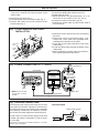
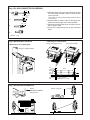
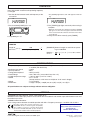
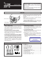
INSTRUCTIONS
HF + 50 MHz AUTOMATIC ANTENNA TUNER
AH-4
Thank you for purchasing the AH-4 AUTOMATIC
ANTENNA TUNER. The AH-4 matches your transceiver to an antenna more than 7 m/23 ft long (3.5
MHz and above).
Please read these instructions thoroughly before installing and operating the AH-4.
DANGERµ
RNEVER use this tuner when it is ungrounded. Always
ground the tuner through the ground terminal before
operating. DO NOT use the mounting plates for
grounding.
Ground terminal
NEVER transmit or tune without an antenna. Failure to
use an antenna will damage the tuner.
Mounting plate
RHIGH VOLTAGE! NEVER touch the antenna while
transmitting or tuning. Place the antenna in a position
where you are sure it will not be touched.
FEATURES
❍ WIDE TUNING RANGE
The AH-4 provides reliable matching of frequencies
from 3.5 MHz to 54 MHz when using at least a 7 m
(23 ft) antenna; or 7 MHz to 54 MHz when using the
AH-2b ANTENNA ELEMENT.
❍ AUTOMATIC DIGITAL CONTROL TUNING
The built-in 8-bit microprocessor chooses the lowest
SWR condition from more than 1,040,000 different
LC (coil/capacitor) combinations.
❍ 45 FREQUENCY MEMORIES FOR FAST TUNING
The LC combinations of 45 previously-used frequencies are automatically memorized in the AH-4. Once
a frequency is memorized, the AH-4 tunes on that
frequency in less than 1 sec. Note that the AH-4
does not memorize a frequency which is normally
tuned within 2.5 sec. Memories are retained only
when the power is on.
❍ WEATHERPROOF DESIGN
The AH-4’s tightly sealed plastic case allows convenient mounting virtually anywhere. The AH-4 can be
mounted outdoors under your antenna.
❍ 0.3 W RADIATED POWER
Radiated power during tuning is less than 0.3 W,
minimizing interference to other stations.
✍ NOTE: 50 MHz tuning is possible with the IC-729*,
IC-706MKII, IC-746 and IC-756; the IC-706 and IC736 can only be tuned 3.5–30 MHz.
* Connect a 50 MHz antenna connector for 50 MHz
operation.
Provided by
http://www.yaesu-museum.com
Downloaded by
Amateur Radio Directory
SUPPLIED ACCESSORIES
u
q
w
i
e
r
t
y
o
!0
q U-bolts .................................................................. 2
w U-bolt plates ......................................................... 2
e Flat washers (M6 large) ........................................ 8
r Flat washers (M6 small) ....................................... 4
t Spring washers (M6) ............................................ 8
y Nuts (M6) .............................................................. 8
u Hex head bolts (M6 × 50) ..................................... 4
i Self-tapping screws (A0 6 × 30) ........................... 4
o PL-259 connectors ............................................... 2
!0 Weatherproof cap ................................................. 1
!1 Control cable (OPC-136; 5 m)............................... 1
!2 Coaxial cable (5D-2V × 5 m) ................................. 1
INSTALLATION
✍ NOTE: After inserting the coaxial cable into the AH4 top cover, solder the PL-259 connector to the
coaxial cable.
➀ Remove the top cover (Fig. 1).
➁ Install the control cable and coaxial cable (Fig. 1).
➂ Connect and solder the PL-259 connector to the
coaxial cable (Fig. 4).
➃ Connect the control cable to the AH-4 (Fig. 2).
➄ Connect the GND cable to the AH-4 (Fig. 3).
➅ Replace the top cover.
➆ Mount the AH-4 in the desired location; on an antenna pole, in your vehicle’s trunk, etc. (Fig. 5).
➇ Connect an antenna to the AH-4 (Fig. 6).
➈ Connect the control cable and the coaxial cable to
the transceiver.
Fig. 1 COVER REMOVAL AND CABLE
INSTALLATION
➀ Remove 8 screws from the top cover and remove
the cover.
➁ Loosen the screws on both cable clamps. If desired, install a strain relief insert (supplied) corresponding to the diameter of the cable.
➂ Install the coaxial cable through the top cover
cable clamp.
➃ Install the control cable through the bottom cover
cable clamp.
➄ After connecting the coaxial cable and control cables, tighten the cable clamp screws.
Strain relief
insert
Coaxial
cable
Control
cable
Cable
clamp
Fig. 2 CABLE CONNECTIONS (ex. IC-706MKII)
Antenna element
AH-2b (optional)
Coaxial cable
IC-706MKII rear panel
black (GND)
red (DC13V)
white (START)
green (KEY)
PL-259
connector
J2
J8
GND
Top cover
✍ NOTE: For the IC-756
and IC-746, connect
to ANT 1.
GND
Bottom cover
Control cable
Fig. 3 GROUND CONNECTIONS
The transceiver and antenna tuner must have an adequate ground connection. Otherwise, the overall effency of the transceiver and antenna tuner installation
will be reduced. Interference, RF feed back and electrical shocks from other equipment could also occur.
For best results, use the heaviest gauge wire or strap
available and make the connection as short as possible. (see right)
• A long wire connected to the GND terminal as a counterpoise is also acceptable.
• Ground example
To AH-4 GND terminal
Copper pipe
Metal object
yyyyyy
;;;;;;
;;;;;;
yyyyyy
;;;;;;
yyyyyy
;;;;;;
yyyyyy
Copper screen
Fig. 4 PL-259 CONNECTOR SOLDERING
30 mm
➀ Slide the coupling ring over the coaxial cable. Strip
➀
Coupling ring
the cable jacket and pull it down to reveal 10 mm
(0.4 in) of braid.
10 mm (soft solder)
10 mm
➁
• Soft solder the exposed braid and then pull the jacket
back in place.
Soft
solder
➁ Strip the cable as shown at left. Tin the center con-
1–2 mm
ductor the entire length of the exposed braid.
➂ Slide the connector body over the cable and sol-
solder solder
➂
der as shown at left.
➃ Screw the coupling ring onto to the connector
body.
➃
(10 mm ≈ 3⁄8 in)
Fig. 5 MOUNTING THE AH-4
• Mounting on an antenna pole
• Mounting on a flat location
Using self-tapping screws
Using nuts and bolts
Using the supplied U-bolts
Nut
Spring
washer
AH-4
Flat
washer
Hex head
bolt
Weatherproof cap
Drill a hole here
(diameter: 6.6–7 mm)
Fig. 6 MOUNTING EXAMPLES
AH-2b
ANTENNA ELEMENT
KIT (optional)
AH-2b + long wire
OPERATION
To ensure the correct impedance match, tune the antenna with the AH-4 each time the operating frequency
is changed.
➀ Set the desired amateur band and frequency of the
transceiver.
• The [TUNER] light flashes and “CW” appears while tuning.
CW
USB
➁ Push and hold [TUNER] for 2 sec.
➂ The [TUNER] light lights constantly when tuning is
complete.
• When the connected wire cannot be tuned, the [TUNER]
light goes out, the AH-4 is bypassed and the antenna
wire is connected to the antenna connector on the transceiver directly.
➃ To bypass the AH-4 manually, push [TUNER].
Push [TUNER] for 2 sec.
CALCULATION OF UNDESIRABLE ANTENNA
LENGTHS
Length of (1/2 λ) =
300
× 1
half wave
operating frequency (MHz) 2
[EXAMPLE] Antenna lengths to avoid when operating at 29.00 MHz
Multiple =
of 1/2 λ
300 × 1 × (1, 2, 3…) = 5.2, 10.3, 15.5 m
29
2
SPECIFICATIONS
• Frequency range
• Maximum input power
• Input impedance
• Tuning power required
• Rated voltage
• Usable temperature range
• VSWR
• Weight
• Dimensions
: 3.5–54 MHz (with an antenna longer than 7 m; 23 ft)
7–54 MHz (with the AH-2b)
: 120 W
: 50 Ω
: 10 W (5–15 W)
: 13.8 V DC ±15% (current drain less than 1 A)
: –10°C to +60°C (+14°F to +140°F)
: 2.0 : 1 or less
(except antennas a half wave or multiple of a half wave in length)
: 1.2 kg (2.65 lb)
: 172(W) × 69.5(H) × 230(D) mm; 625⁄32(W) × 63⁄4(H) × 91⁄16(D) in
All specifications are subject to change without notice or obligation.
OPTIONS
• OPC-420 SHIELDED CONTROL CABLE (cable length 10 m)
Shielded control cable helps protect the transceiver from RF feedback and extends separation between tuner and
transceiver up to 10 m.
• AH-2b ANTENNA ELEMENT
A 2.5 m long antenna element for mobile operation with AH-4. Frequency coverage: 7–54 MHz with the AH-4.
The AH-4 complies with essential requirements of the
89/336/EEC directive for Electromagnetic Compatibility.
This compliance is based on conformity with the ETSI
specification ETS300 684 (EMC product standard for
Commercially Available Amateur Radio Equipment).
Provided by
http://www.yaesu-museum.com
Downloaded by
Amateur Radio Directory
Count on us!
6-9-16 Kamihigashi, Hirano-ku, Osaka 547-0002 Japan
A-8295G-1EX
Printed in Japan
Copyright 1997 by Icom Inc.