1
All data connectors (four yellow, one black, one
in-line) are keyed and will only attach when
oriented correctly. Do not force these
connectors. The threaded antenna connectors are
not keyed.
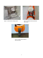
Begin by placing the Hydrolink transceiver and
the Trimble GPS units on end inside the hatch as
shown in Figure 6.
Connect the MaxRad stub antenna cable to the
Hydrolink transceiver, and connect the GPS
antenna cable to the GPS receiver.
Now the data cables: connect the ADCP data cable
to Hydrolink transceiver port A. Connect the data
jumper cable to port B on the Hydrolink and Port
A on the GPS receiver. Attach the depth sounder
connector cable to its internal mate (this small
threaded in-line connector is keyed), and attach its
yellow data connector to Port C on the Hydrolink
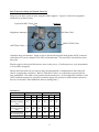
transceiver. Slide the transceiver and the GPS
unit into the compartment, and then nest two of
the foam spacers between them and towards the
bow, as shown (Fig. 5). Place the other small
foam spacers against the stern. These will keep
the battery from traveling during deployment.
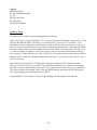
Finally, place the battery between the GPS and the
transceiver, and add the thin foam spacers on
either side (see fig. 8). You’re ready for power
connection.
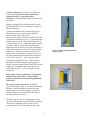
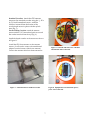
Figure 3. Depth sounder internal data
connector cable.
Battery note: We’ve provided two 7.2 amp-hour
batteries with your system. Expect about 5
hours of service from each fully charged battery
in the field.
Be sure the power switch is off. Install the
ground wire splitter (Fig. 2) onto the black battery
terminal. Attach the black wire from the data
jumper cable to one of the splitter’s connectors,
and the black wire from the ADCP data cable to
the other splitter connector.
The fused red power wire originating from the
on/off switch attaches to the red battery terminal;
connect the remaining red wire from on/off
switch to the red wire of the data jumper cable.
6