1
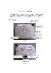
V3E840/V319B00
MITY-SERVO VEA type
User’s manual
MODEL : VEAS-□□, VEA-□□, VEA-□□□
∼AC200V Series∼
Please ensure that this user's manual is delivered to the final customer who will be
operating this product.
MS-TECHNO, Inc.
Safety Precautions
● Before installation operation, maintenance, or inspection, be sure to read and follow this
user's manual and supplemental in detail use only after becoming familiar with the unit,
safety information, and precautions.
This user's manual categorizes safety precaution as a DANGER or CAUTION.
● Safety symbols used in this manual
The text uses the following symbols to represent various safety precautions.
DANGER
Used where improper action can lead to hazardous conditions that may
result in severe injury or death.
CAUTION
Used where improper action can lead to hazardous conditions that may
result in moderate damage or minor injuries, or strictly material damage
only.
However, under certain conditions, even items categorized marked with
CAUTION can also lead to serious injuries / damage.
Therefore, strict compliance with all CAUTION warnings is urged.
●Below are the symbols used to mark items marked as PROHIBITED and REQUIRED,
followed by brief explanation of each category.
PROHIBITED
Marks prohibited items. For example, in cases where open sparks/fires
are prohibited, the following mark is used:
REQUIRED
Marks item where compliance is required. For example, where an
item must be grounded this symbol is used:
●This manual will also appropriately note items that the user is recommended to follow, although they are
not classified as DANGER or CAUTION.
1. On Installation
CAUTION
●Operate in environments specified in catalog and user's manual (refer to Section 3).
Avoid usage in areas of high temperature or humidity; or exposure to excessive dirt, corrosive gases,
vibration, or shock. These conditions may risk electrocution, fire, or malfunction.
Specific conditions to avoid:
・ Avoid direct sunlight or areas with temperatures below -10℃ or above 40℃.
・ Avoid areas with humidity over 90% or where rapid temperature changes may lead to
condensation.
・ Avoid exposure to corrosive or flammable gases.
・ Avoid areas where direct vibration or shock may after the MITY-SERVO.
・ Avoid areas where the unit may be exposed to water, oil or other chemicals.
・ Avoid areas in close proximity to flammable materials.
●Follow the manual to secure and attach the unit (refer to Section 3).
Improper installation can lead to falling of the unit, machine failure, or malfunction.
1. Please ensure the proper and secure tightening of attachment screws.
Confirm the proper tightening of MITY-SERVO attachment screws and terminal securing screws
to prevent loosening. The loosening of screws can cause the unit to fall or unit malfunction.
2. Make sure that unit is properly oriented when being secured!
MITY
MITY
●Do not allow refuse such as wire scraps inside of the unit.
Failure to do so may lead to fire, machine failure or malfunction.
2. On Wiring
REQUIRED
●Be sure ground the grounding terminal, maked with the name plate E (refer to Section 3).
Failure to ground the unit may lead to electrocution or malfunction.
Connect the MITY-SERVO power terminal box terminal "E" to the ground electrode (type 3 ground)
with a wire 2mm2 or more.
Do not share this grounding conductor with other powered equipment.
CAUTION
●Connect to a rated power source (refer to Section 3).
Connecting to a power source of an incorrect rating may lead to fire or machine failure.
Based on the model series of the MITY-SERVO on the following 2 power ratings will be used.
Be sure to use the correct power source.
AC 200V / AC 400V
VEA type is AC200V.
(VEAH type is AC400V)
●Wiring operations should be performed by an electrician or other specialist.
Improper wiring may lead to fire, machine failure, or electrocution.
●Be sure that the all connectors to the MITY-SERVO are connected properly.
Failure to do so may lead to malfunction of the MITY-SERVO.
Countermeasures for Power Source Noise
●Connect an insulating transformer or filter to the external power source when noise
becomes a problem (refer to Section 5).
This will prevent malfunction of the MITY-SERVO and its peripheral devices.
Insufficient noise countermeasures may result in malfunction.
Proper Laying of External Wiring
●Consider the following conditions when selecting the input/output wires
(external wiring) from the MITY-SERVO to external devices (refer to Section 3).
・Mechanical strength
・Affect of noise
・Wiring distances
・Signal voltage and current
Wiring and housing of input/output wiring should be separated from power lines both inside and
outside of the control panel.
This will reduce noise affects. Insufficient separation may lead to malfunction.
●Use twisted pair shielded wires for the MITY-SERVO encoder wires (refer to Section 3).
This will reduce the affect from noise, preventing malfunction.
Usage of cables other than those specified may lead to malfunction.
3. Precautions Before Usage
DANGER
●Do not touch terminal when powered.
This may lead to electrocution.
●Do not touch the regenerative resistor or resistor terminal when powered.
This may lead to electrocution.
●Emergency stops and interlock circuits should be external to the MITY-SERVO unit.
Malfunction or machine failure of the MITY-SERVO may lead to machine damage or accidents.
Safety countermeasures external to the MITY-SERVO!!!
An external interlock circuit should be set up when MITY-SERVO machine failure may risk
Bodily injury or damage to products or accessory devices.
(EX.) When using in motorized carts or cargo hauling equipment (such as cranes):
MITY-SERVO machine failure may allow motors to run freely, possibly leading to loss
of cart control, or dropping of cargo. These may in turn result in damage to products or
accessory devices, or bodily injury.
Normally, mechanical brakes are attached to the motor, and an interlock circuit built into
the MITY-SERVO QMCL program.
An external relay should be set up with a similar interlock circuit.
●Ensure safety before testing the input/output signals.
Movement of the device can lead to bodily injury or damage products or accessory devices.
Safety First when confirming input/output signals
When testing brakes on moving units:
Devices going in motion may lead to bodily injury or cause damage to accessory devices,
use temporary measures such as stop blocks or catches (to prevent the dropping
of objects).
CAUTION
●Use extreme caution when changing parameters or using keyboard control while MITY-SERVO is
in motion. Improper operation may lead to equipment damage or accident.
●Remove power in the order specified. Malfunction may lead to equipment damage or accidents.
1. Turn on power starting with sub machines.
When operating using MITY-SERVO’s communications system (multiple main/subsidiary
operation or host computer control), turn on the subsidiary machine of MITY-SERVO.
If the main machine is turned on first, malfunction or damage may result due to the input/output
signal delay from the subsidiary machine.
2. Ensure interlock between the main and subsidiary machine when stopped.
Failure to do so may lead to malfunction or damage.
●Attach protective fuses (such as circuit breakers) between load and output.
Overloads or short circuits can cause damage or fires.
Protective fuses are not included in MITY-SERVO’s output.
●Attach temperature control unit to motor.
Heat buildup may lead to scorching, damage or even fires.
●Attach cooling device to motor.
Heat buildup may lead to scorching, damage or even fires.
When using the motor continuously at low speeds, use a motor rated for continuous use.
Otherwise, use a cooling device as specified.
●Do not touch MITY-SERVO unit or motor-regenerative resistor directly after operating
or removing power from the unit.
Heat buildup may lead to scorching/burning, damage or even fires.
●Confirm that operating signals and input are off before attempting to reset system
or restoring power.
Sudden unexpected motions may result, leading to equipment damage or accidents.
Keyboard Operations During Operation Requiring Special Care
●Do not exceed the range when changing System parameter or User parameters.
Malfunctions may lead to equipment damage and accidents.
●Only those thoroughly familiar with the contents and method of operation should manipulate
the System parameter or user parameters.
●Do not change System parameter No. 71 (encoder correction) after it is first set.
Malfunctions can lead to equipment damage and accidents.
System parameters are set based on the motor and the encoder pulse numbers.
Source Program of QMCL
●MITY-SERVO controls the motor according to the program (QMCL).
The program is written in the RAM or ROM on the CPU board.
It is recommended that a file of source program be obtained for use in emergencies.
4. On Maintenance
DANGER
●Avoid miswiring, removing, or shortcircuiting the power source; disassembling the MITY-SERVO
unit, or exposing unit to heat or open flames.
This may lead to explosion or fire.
PROHIBITED
●Do not disassemble or modify the MITY-SERVO unit.
This may result in fire, machine failure, or malfunction.
CAUTION
●Turn off power and wait over 5 minutes, confirming that terminal box P-N voltage is below DC24V
before connecting or disconnecting the MITY-SERVO unit.
Misoperation may lead to electrocution, equipment damage, or accidents.
●The voltmeter used to measure the voltage of the terminal box P-N voltage should be able to measure above
DC 400V.
The P-N voltage measure DC280V∼DC400V immediately after shutting down power.
【CONTENTS】
Section 1: Functions and Characteristics of the MITY-SERVO
1-1
1-1-1
1-1-2
1-2
1-2-1
1-2-2
On the MITY-SERVO
Outline of the MITY-SERVO
Characteristics of the MITY-SERVO
Function and Operation of MITY-SERVO
Structure
On Memory Backup
Section 2: System Structure of the MITY-SERVO
2-1
2-1-1
2-1-2
2-1-3
2-1-4
2-1-5
2-2
2-2-1
2-2-2
Standard Specifications of the MITY-SERVO
CPU
Encoder Input
A/D Input
I/O Input
I/O Output
MITY-SERVO Options
RS232C / RS422
FLASH-A-QM
Section 3: MITY-SERVO Installation and Wiring
3-1
3-1-1
3-1-2
3-1-3
3-1-4
3-1-5
Installation Precautions
Location
Ambient Temperature
Relative Temperature
Vibration
Environment
3-2
Wiring
3-2-1
3-2-2
3-2-3
Connecting and Wiring MITY-SERVO
Wiring Precautions
Peripheral Equipment
3-2-4
3-2-5
3-2-6
3-3
3-3-1
3-3-2
3-3-3
Adapters
Input/Output and Encoder Wiring
Confirming Input/Output and Encoder Pulses
MITY-SERVO Operation
Operating Precautions
Source Program (Source QMCL)
CPU Battery
Section 4: MITY-SERVO Programs
4-1
4-1-1
4-1-2
4-1-3
4-1-4
4-1-5
MITY-SERVO Programs
On QMCL
Operating the Motor
Creating Programs
QMCL System
System Parameters and User Parameters
Section 5: Troubleshooting
5-1
5-2
5-3
5-4
5-5
Error Message
Protective Functions of MITY-SERVO
Troubleshooting
Preventive Measures and Safety
Servicing MITY-SERVO
Section 1 : Functions and characteristics of the MITY-SERVO
1-1
1-1-1
1-1-2
1-2
1-2-1
1-2-2
On the MITY-SERVO
Outline of the MITY-SERVO
Characteristics of the MITY-SERVO
Function and Operation of MITY-SERVO
Structure
Backup of CPU board
1-1
On the MITY-SERVO
This section will outline the MITY-SERVO unit and explain characteristics.
1-1-1
Outlines of the MITY-SERVO
The MITY-SERVO is a programmable controller capable of controlling the revolutions and torque output for
induction motors.
Rotary encoder positioning with standard 12 input / 8 output sequence function (analog input) allow a high
level of control.
● Example of a Common MITY-SERVO Connection Setup
The following is an example of the wiring and connection of the MITY-SERVO.
Three phases AC200V
Breaker
Noise
MITY-SERVO
Filter
R
S
GND
Input Common
T
C4-D0
Servo On
C4-D1
Start/Stop
C4-D2
Reverse (CW)
DC24V
Output Common
Personal
RS232C
Computer
DC24V
C0-ALM
GND
C0-D0
Relay
Error
DC24V
P
Regenerative resistor
Relay
Encoder
So
E
U V W
Induction
Encoder
Motor
Servo Ready
1-1-2
Characteristics of the MITY-SERVO
The MITY-SERVO programmable controller has the following characteristics.
● Digital control using 32bit CPU + MS techno original LSI.
● Simple programming, using the MITY-SERVO dedicated “QMCL”. *1
● Low speed operation. (approximately 1 rpm)
● Standard locating and sequencer functions included, making it unnecessary to prepare separately.
● Communication function (optional) makes it possible to control the unit via personal computer, and
run diagnostic programs.
*1
QMCL :
“Quick Motion Control Language” , a language created by MS techno to facilitate motor control.
● A variety of input and output functions
Digital input
Digital output
Analog input (DC0-5V)
Encoder input (L/D)*2
Communication function
*2
12
8
1
1
RS232C/RS422
L/D : Line driver method
● Creating and Editing Programs
The“QMCL System 98” makes easy the creation and edition of programs.
Programs created can be transferred from personal computer into the MITY-SERVO, using the
QMCL System 98 and the optional communication board. (sold separately).
“FLASH-A-QM” is the writing of programs and parameters to ROM.
“FLASH-A-QM” is a MITY-SERVO optional that writes to ROM.
1-2
Function and Operation of the MITY-SERVO
This section will outline MITY-SERVO function and operation.
1-2-1
Structures
The MITY-SERVO is comprised of the following areas, including the CPU, driver, power source, and main
circuit, as shown below:
CPU
The CPU is comprised of the processor (IMC-04), control circuit, and I/O.
・Processor
House the MITY-SERVO operating system (OS).
Control parameter memory. RAM and ROM reside here.
・RAM
Houses the QMCL and used as data area, with 3.2KB capacity.
・ROM
Houses the QMCL and used as data area, with 8KB×4 zone.
・Control circuit
Outputs motor control signals / PWM signals.
・I/O
Manages external input and output signals, encoder input and analog input signals.
Driver
The driver processes output motor control signals from the CPU and transmits it to the main Circuit.
Power source
Using the specially designed switching regulator, the power source provides regulating power to the CPU and
the driver.
Main circuit
The main circuit consists of a rectification, smoothing, and inverter circuits.
The power source (3 phase AC 200V) and the motor are connected the main circuit.
DANGER
The driver power source and main circuit are of very high voltage. Do not touch any of these parts.
Failure to comply may lead to bodily injury or electrocution.
1-2-2
Backup of CPU Board
The CPU is equipped with read/write able memory (RAM), with a Ni-Cd battery that preserves memory in case
of power loss.
Check battery power loss when not using the MITY-SERVO for prolonged periods of time.
Take note that memory contents may be altered in the following cases:
・When battery voltage drops below 2.5 V.
・When the MITY-SERVO has not been used for 3 months or more.
・After the CPU board has been removed or contents were manipulated.
IMPORTANT !!
The MITY-SERVO’s System parameters and User parameters are stored in the RAM.
Note that low battery levels dead batteries will reset the System parameters to their default values.
・Contact MS techno for further information when replacing batteries due to normal wear or in case of
problems.
DANGER
Do not expose dead batteries or CPU boards to fire . This may result in explosion.
● Ni-Cd battery used : GS / 3GB-60MX 3.6V 50mAh
SECTION 2 : System structure of the MITY-SERVO
2-1
Standard specifications of the MITY-SERVO
2-1-1
2-1-2
2-1.3
2-1-4
2-1-5
CPU
Encoder Input
A/D Input
I/O Input
I/O Output
2-2
MITY-SERVO Options
2-2-1
2-2-2
RS232C / RS422
FLASH-A-QM
2-1 Standard Specifications of the MITY-SERVO
This section will explain standard specifications of the MITY-SERVO.
2-1-1
CPU
● The QMCL program for motor control can be written to RAM and ROM aria.
・RAM aria
3.2 KB
Max 423 lines
・ROM 0 aria
8 KB
Max 1023 lines
・ROM 1 aria
8 KB
Max 1023 lines
・ROM 2 aria
8 KB
Max 1023 lines
・ROM 3 aria
8 KB
Max 1023 lines
● Edit and change the QMCL program and parameter values using the keyboard.
Program contents, parameter settings and other values can be seen on the display (using line 10, segment 7).
2-1-2
Encoder
● 1 channel is made available for encoder input. (Feed back pules)
● A line driver type (DC5V) encoder can be used.
Use pulse settings in the 200Kpps range, at 2000C/T or higher.
When using settings other than those shown above, confirm that they are within the encoder’s specified
ranges.
MS-techno uses standard stock of 2500C/T.
● Generally, the encoder is connected directly to the motor.
Follow precautions listed in the encoder catalog or user’s manual when making connections.
● Connector number
CN7
● Housing
MOLEX5251-08
(5051 N-08)
● Crimp-Style terminal
MOLEX 5659
IMPORTANT !!
Be sure to the QMCL parameter number 71 “Encoder correction” to the encoder pulse settings.
IMPORTANT !!
The encoder input is connected directly to the CPU power source.
Take care to avoid short circuiting and improper wiring.
(5159)
2-1-3
A/D Input
● 1 channel is available for analog input.
● Input are DC0V-5V signal.
● Connector number
CN6
● Housing
MOLEX5251-03
(5051 N-03)
● Crimp-Style terminal
MOLEX 5659
(5159)
IMPORTANT !!
If input may exceed DC5V when turning on power, insert a clamping diode or take other precautions.
IMPORTANT !!
Analog input signal is connected directly to the CPU power source.
Be sure to avoid short circuiting and improper wiring.
2-1-4
I/O Input
● Input ports C4 have 8 inputs and C5 have 4 inputs. (Total : 12 inputs).
● The GND ports are common with an I/O power source of GND(0V).
● The inputs are insulated by photocoupler.
● Power source specification : DC24V 5mA dynamic current type.
● Connector number
C4 : CN14
C5 : CN15
● Housing
● Crimp-style terminal
C4 : MOLEX5251-10
(5051 N-10)
C5 : MOLEX5251-06
(5051 N-06)
MOLEX5659
(5159)
● For DC24V, prepare an appropriate I/O power source.
Electric Circuits:
I/O DC24V
Relay, etc
Photocoupler
I/O GND
2-1-5 I/O Output
● Output ports C0 have 8 outputs.
● The DC24V ports are common with an I/O power source of DC24V.
● The output are insulated by photocoupler.
● Power source specification : DC24V open collector current type (emitter COM) 40mA.
Be sure not to surpass the output current range.
(The output is not protected from over current).
Use a surge protection diode for the relay control coil.
Pay attention to the polarity of the diode when making connection.
● Connector number
CN10
● Housing
MOLEX5251-11
(5051 N-11)
● Crimp-style terminal
MOLEX5659
(5194)
● For DC24V, prepare an appropriate I/O power source, separately.
Electric Circuits:
I/O DC24V
Relay, etc.
Transistor I/O GND
2-2 MITY-SERVO Options
This section will explain MITY-SERVO’s options.
2-2-1 RS232C / RS422
● Establishes communications between the MITY-SERVO and PC, PLC, or with another MITY-SERVO unit.
RS232C
dedicated cable:
1m;25-pin or 9-pin D-sub connector.
(25-pin connector No: JF3P-255, 9-pin connector No: DE-9S-UL).
RS422
dedicated cable:
inter-MITY-SERVO connectors available upon order.
dedicated cable:
1m;Non-treated ends.
dedicated cable:
inter-MITY-SERVO connectors available upon order.
● Be sure to remove power before connecting or disconnecting the MITY-SERVO.
2-2-2 FLASH-A-QM
● Connecting FLASH-A-QM to the MITY-SERVO makes it easy to write program and parameter to ROM.
Be sure to remove power before connecting or disconnecting the MITY-SERVO.
For more details, refer to the FLASH-A-QM user’s manual.
I/O connectors on the CPU board <V3E840>
Don’t touch!!
A/D Input
CN6
FLASH-A-QM
CN2
RS232C
CN3
Encoder
CN7
CN10
C0 Output
CN1A
DC24V&GND
CPU board
CN14
C4 Input
Keyboard/Display
CN15
RS422
Don’t touch!!
CN8
C5 Input
Section 3 : MITY-SERVO Installation and Wiring
This section explains how to install and wire MITY-SERVO.
3-1
3-1-1
3-1-2
3-1-3
3-1-4
3-1-5
3-2
3-2-1
3-2-2
3-2-3
3-2-4
3-2-5
3-2-6
3-3
3-3-1
3-3-2
3-3-3
Installation
Location
Ambient Temperature
Relative Humidity
Vibration
Environment
Wiring
Connecting and Wiring MITY-SERVO
Wiring Precautions
Peripheral Equipment
Adapters
Input/Output and Encoder Wiring
Input/Output and Encoder pulse Check
MITY-SERVO Operation
Operating Precautions
Source Program (Source QMCL)
CPU Battery
3-1
Installation
Install MITY-SERVO at that meet the following conditions below to ensure proper operation and
maximum performance.
3-1-1
Location
Select a location that meet the following conditions:
a.
Inside a building with o water leakage or water intrusion and relatively low humidity.
b.
Explosion-proof environment with no flammable gasses or liquids and little dust.
c.
No flammable objects nearby.
d.
Easily accessible for inspection and servicing.
e.
Heat generated by MITY-SERVO or peripheral equipment can be released.
f.
Install at a location where MITY-SERVO may be isolated from equipment that emits noise or
is affected by noise.
3-1-2
Ambient Temperature
Monitor the ambient temperature to ensure performance of MITY-SERVO long-term.
Normal operation range for MITY-SERVO is -10°C to 40°C. Keep the ambient temperature in this
range at all times. Install a cooling system to lower the temperature if the temperature may exceed 40°
due to the heat generated by MITY-SERVO.
3-1-3
Relative Humidity
Install MITY-SERVO at a location where relative humidity stays below 90 % and ensure
MITY-SERVO is free from condensations. High humidity causes oxidation and corrosion of metal areas
on MITY-SERVO, leading to improper insulation.
3-1-4
Vibration
Install MITY-SERVO at a location with little vibration. Follow are guidelines below:
For Vibration acceleration ≦ 20Hz → Vibration ≦ 1.0 G
For Vibration acceleration 20 – 50 Hz → Vibration ≦ 0.2 G
Use rubber cushions to vibration proof MITY-SERVO if it will be installed at location where
MITY-SERVO will be subjected to severe vibrations, such as on a conveyor.
3-1-5
Environment
Select a location that is free from flammable or corrosive gasses, oil and water. Make sure
MITY-SERVO is protected from electrically conductive dust, such as metal shavings. If necessary, install a
filter on the control panel to prevent dust from coming inside.
3-2 Wiring
3-2-1
Connecting and Wiring MITY-SERVO
The table below shows MITY-SERVO terminals and their usage.
Terminal
Codes
R, S, T
U, V, W
Terminal Name
AC
power
source
connectors
Motor connectors
E
Ground
P
DC positive terminal
So
N
Usage
Connect to AC
Connect to U, V, and W wires on motor
Connects to ground
Connects to regenerative resistor; DC positive
terminal
resistor
Connects to regenerative resistor
Regenerative
terminal
DC negative terminal
DC negative terminal
Connect main circuit wires according to the table above.
CAUTION
●Use only the standard rated power source (AC200V) ; failure to do so may cause fire or damage
to
the unit.
●Only qualified electricians may wire MITY-SERVO; incorrect wiring may cause fire, damage to
the unit, or lead to electrocution.
●Wait five (5) minutes after turning the power source off before proceeding any work on power source
terminal blocks. Make sure the voltage between P and N terminals has dropped below DC 24V.
Failure to observe these precautions may result in electrocution, malfunction of MITY-SERVO,
d
t th
it
Power Source Terminal Wiring Diagram
E
R
S
T
Ground
Three Phases AC180∼230V
Terminal
50/60Hz
U
V
W
So
N
P
Regenerative Resistor
I.M
Single Phase AC200V
Three Phases Induction Motor
50/60Hz
REQUIRED
●Make sure the ground terminal, E, displayed on the power source terminal block nameplate,
is connected to the ground. Failure to ground may cause electrocution or malfunction of MITY-SERVO
●Use wires of 2 mm2 or larger to connect MITY-SERVO power source terminal block E to the
ground (Type 3 ground). Do not use the same wire for other power equipment.
Poor Example : Main circuit and I/O are the same
Good Example : Main circuit and I/O are separate
Sequencer
Sequencer
MITY-SERVO
MITY-SERVO
Motor
Motor
Encoder
Encoder
Poor Example : There is more than one ground
MITY-SERVO
MITY-SERVO
Shielded cable
3-2-2
Good Example : There is only one ground
Shielded cable
Wiring Precautions
Follow the guidelines below to ensure MITY-SERVO will stay problem-free.
1.
Take current capacity, voltage drop, and other relevant factors into account to select main circuit
cable size.
2.
Make sure the main circuit and signals, such as input/output and encoder, are separately wired.
3.
Use twisted-pair shielded wire or instrumentation shielded wire for encoder RS232C and RS422
signal.
4.
Minimize the cable length.
5.
Ground shielded cable at one point only.
6.
Use an effective means of insulation, such as the use of conduits, if signals may be affected by
noise interference.
7.
Please contact MS techno to extend display or keyboard cable length.
8.
Make sure connectors to MITY-SERVO are securely attached.
Peripheral equipment must be selected carefully to ensure proper operation and optimum performance
of MITY-SERVO.
●Cables
Power:
Consider the following to select appropriate size cable: power source capacity, shortCircuit protection, temperature increase, voltage drop, and terminal structure. Apply the same criteria
used to select general power cables.
The effect of voltage fluctuations is greater when the cable length is long between
MITY-SERVO and the power source or the motor. This may lead to insufficient motor torque and increase
in current, causing the motor or cable to overheat. Use larger size cable than specified in the table on the
next page to prevent overheating when the distance is great between MITY-SERVO and the power source
or the motor.
Longer cable between MITY-SERVO and the motor may also cause the static electricity to build up
between each wire and ground, increasing leakage current. In some cases, this may cause the circuit
breaker to operate. Circuit breaker for inverters (Leakage of electricity detection ≧200mA) may be used
to counter this situation.
The shortest possible length of an appropriate size should be used for power source.
Controls:
Use 2mm2 or larger size for power source cable in the control circuits. For operations and signal circuits,
use cables that are appropriate size for the current in each circuit.
Use shielded cable whenever possible for signal circuits to reduce noise interference.
Make sure to use a separate cable for power source for control and power source from the unit power
cable.
Use shielded cables or twisted-pair shielded cables for signal circuit in consideration of cable length and
outside noise interference.
Signals may need to be amplified by signal insulator to counter noise interference when a long cable is
used.
Conduits may need to be used to isolate noise if may malfunction of MITY-SERVO.
●Breakers
The purpose of inserting a breaker on the power source side of inverter is to protect the power circuits
from shorting and to protect against overloading.
Select a breaker appropriate for the capacity.
Select guidelines are shown in the table on the following page.
Peripheral Equipment Selection Guidelines
Model
VEAS-01
VEAS-02
VEAS-04
VEAS-08
VEA-15
VEA-22
VEA-37
VEA-55
VEA-75
VEA-110
VEA-150
VEA-220
VEA-300
VEA-370
VEA-450
VEA-550
Main circuit
Breaker
ElectroMagnetic
Contactor
30 AF/5 AT
30 AF/5 AT
30 AF/5 AT
30 AF/10 AT
30 AF/20 AT
30 AF/20 AT
30 AF/30 AT
50 AF/50 AT
100 AF/60 AT
100 AF/100 AT
225 AF/125 AT
225 AF/175 AT
225 AF/225 AT
400 AF/300 AT
400 AF/400 AT
400 AF/400 AT
8A (S-A10)
8A (S-A10)
8A (S-A10)
8A (S-A10)
12A (S-A11)
12A (S-A11)
20A (SK-20)
35A (SK-35)
50A (SK-50)
65A (SK-80)
80A (SK-80)
125A (SK-125)
150A (SK-150)
220A (SK-220)
220A (SK-220)
300A (SK-300)
Cable Diameter
R, S, and T Cables
2 (mm2)
2 (mm2)
2 (mm2)
2 (mm2)
3.5(mm2)
3.5(mm2)
5.5 (mm2)
5.5 (mm2)
8 (mm2)
14 (mm2)
22 (mm2)
38 (mm2)
60 (mm2)
100 (mm2)
100 (mm2)
100 (mm2)
U, V, and W Cables
2 (mm2)
2 (mm2)
2 (mm2)
2 (mm2)
3.5(mm2)
3.5(mm2)
5.5 (mm2)
5.5 (mm2)
8 (mm2)
14 (mm2)
22 (mm2)
38 (mm2)
60 (mm2)
100 (mm2)
100 (mm2)
100 (mm2)
Electro-magnetic contactor model names in parentheses are MITSUBISHI model names.
Selecting Peripheral Equipment for VEA series:
Select peripheral equipment for VEA series carefully to avoid overheating or voltage drop since the momentary
current may exceed the rated current value by several times, depending on usage conditions.
Large size cable than shown in the table above may be used or large capacity peripheral equipment may be
substituted, depending on the usage.
3-2-4
Adapters
Input/Output Signal Connectors:
CPU Board Wiring Inside
MITY-SERVO
Accessory Lead Wire
Standard Lead Wire Length 1 m
Input: C4
Molex 5046-10P
5251-10P (Pin 5659)
5051-10P (Pin 5159)
Input: C5
Molex 5046-6P
5251-6P (Pin 5659)
5051-6P (Pin 5159)
Output: C0
Molex 5046-11P
5251-11P (Pin 5659)
5051-11P (Pin 5159)
CPU Board Wiring Inside
MITY-SERVO
Accessory Lead Wire
Standard Lead Wire Length 1 m
Molex 5046-8P
5251-8P (Pin 5659)
5051-8P (Pin 5159)
CPU Board Wiring Inside
MITY-SERVO
Accessory Lead Wire
Standard Lead Wire Length 1 m
Molex 5046-3P
5251-3P (Pin 5659)
5051-3P (Pin 5159)
Encoder Connectors:
Encoder: ENC1
Analog Input Connectors:
Analog Input: A/D
+24V (I/O) Power Source Connectors:
+24V Power Source:
CNP1
CPU Board Wiring Inside
MITY-SERVO
Accessory Lead Wire
Standard Lead Wire Length 1 m
Molex 5046-2P
5251-2P (Pin 5659)
5051-2P (Pin 5159)
Note; “Pin” in the tables refer to crimp-style terminals.
3-2-5
Input/Output and Encoder Wiring
MITY-SERVO has a variety of external functions such as sequencer input/output, encoder input, and
analog input.
Please refer to appropriate user manuals for cable and connector part numbers.
Input/output:
Photocopiers are used to insulate input/output areas.
Output specifications are open collector (emitter COM).
Electric Circuits:
Input: Current limiter resistor is connected inside. Connect relays and limit switches.
I/O DC24V
Relay, etc
Photocoupler
I/O GND
Output: Open collector COM. Maximum current is 40mA.
Connect controls such as relays. Do not exceed the Maximum output current.
Match the polarity of relays, if applicable.
Some relays may require surge-protective diode.
Use a mini-relay if the control current may exceed the allowable value.
I/O DC24V
Relay, etc.
Transistor I/O GND
Encoder: For line receiver.
Line Receiver
Line Driver
IMPORTANT !!
●There are two power sources for outside input/output, depending on specifications: I/O and CPU.
Incorrect wiring of those may cause malfunctions or damage to the unit.
The 0V for I/O and CPU may not be shared.
I/O : I/O +24V, I/O 0V (input/output C4, C0)
CPU : CPU +5V, CPU 0V (A/D, encoder)
●Obtain a separate DC +24V I/O power source cable appropriate for capacity.
3-2-6 Input/Output and Encoder Pulse Check
Follow the directions below to check MITY-SERVO input/output and encoder pulse.
Input
Check that outside signals are received by MITY-SERVO. Turn on operation switch and limit switch to
verify input signals are received.
MITY-SERVO should be in editor mode for checking.
1.
Turn the power on (AC200V) and press the END key on the MITY-Servo’s keyboard.
.
The period “.” will be flashing at the left edge of the display.
MITY-SERVO is now in the editor mode.
2.
To check input signal C4:
3.
Enter the following from the keyboard:
C
4
CR
The display will show as follows:
C 4
.
X X X
The bits that are on will be displayed in binary.
D0=1,
D1=2,
D2=4,
D3=8,
D4=16, D5=32, D6=64, D7=128
For example, if the operation switch is connected to C4-D0, the display will show as follows when
this switch is turned on:
C 4
.
1
4.
Press the CR key to check repeatedly.
5.
To check C5 port, input C, 5 and press the CR key.
Output
MITY-SERVO transmits signals to other devices. Check brake release and sequencer reading.
Produce:
1. Set MITY-SERVO in the editor mode (See Input section on the previous page).
2. To check output C0 port:
3. Enter the following from the keyboard.
C
0
?
CR
The display will show as follows:
C 0 ?
Pressing the CR key will return MITY-SERVO to the editor screen.
Enter the following to turn off the output signals:
4. The output signal will stay on until it is turned off.
5. Enter the following to turn off the output signal:
C
0
0
CR
6. To check more than one bit at the same time, add the bit numbers and enter.
Example: To check output signals D0 and D7 at the same time, enter 129
(Since D0=1 and D7=128, 1 + 128 = 129).
C
0
1
2
9
CR
DANGER
●Check safety before checking input/output signals.
Failures to do so may cause the machine to move, causing bodily injuries or damages to the unit
or accessory equipment.
Encoder Pulse Check
Check that encoder signal is input into MITY-SERVO
Procedure:
1. Set MITY-SERVO in the editor mode (See input section on the previous page).
2. Enter the following from the keyboard.
E
2
CR
The display will show as follows:
.
E 2
X X X X X X
Note: XXXXXX = encoder pulse count.
3. Press the CR key repeatedly.
Rotate the motor in the positive direction, counterclockwise (CCW) viewed from the axis, and check that
The encoder pulse count increases.
Rotate the motor in the reverse direction, clockwise, and check that the encoder pulse count decreases.
If the pulse count does not change, increases when the motor is rotated in reverse or decrease when it is
Rotated in the positive direction, phase A and phase B signals may be reversed. Check the wiring and
Correct if necessary.
IMPORTANT !!
Make sure to check encoder pulse before operating MITY-SERVO for the first time.
Check encoder phase if pulse does not count correctly.
The reverse and non-reverse signals may be connected wrongly the same phase.
3-3
MITY-SERVO Operation
3-3-1 Operation Precautions
After installing MITY-SERVO, check wiring once again before operating. After the operation, check the
following to verify there are no problems:
1.
Check that MITY-SERVO unit did not overheat.
2.
Check that motor did not overheat.
3.
Check that regenerative resistor did not overheat.
4.
Check that power cables for motor did not overheat.
5.
Check for vibrations or noise caused by MITY-SERVO, motor, or machine.
6.
Check that the cables are not pinched.
7.
Check that fasteners have not loosened.
Stop the operation immediately and correct the situation if there are any problems.
Friction of the machine may decrease stopping accuracy drastically; for locating operation, run the machine
for a sufficient period of time to ensure smooth movements.
Friction may also cause the stop location to change as the machine continues to run. Change the parameters
on MITY-SERVO to make any adjustments. (See software manual for details.)
3-3-2 Source Program (Source QMCL)
MITY-SERVO controls the motor according to the program (QMCL). The program is written in the RAM or
ROM on the CPU board. It is recommended that a source program file be obtained for use in emergencies.
3-3-3 CPU Battery
The MITY-Servo’s CPU has a built-in memory back-up battery. Since the contents of the memory may
become outdated when it is not used in a long time, check the battery charge periodically and charge it when
it becomes too low. The battery will take approximately one day (24h) to fully charge.
Section 4: MITY-SERVO Programs
4-1
MITY-SERVO Programs
4-1-1
4-1-2
4-1-3
4-1-4
4-1-5
4-1
on QMCL
Operating the Motor
Creating Programs
QMCL System
System Parameters and User Parameters
MITY-SERVO Programs
4-1-1 on QMCL
QMCL stands for Quick Motion Control Language, a programming language which enables quick motor
movement.
QMCL controls MITY-Servo’s basic motor movement.
4-1-2 Operating the Motor
The MITY-SERVO unit cannot operate on its own.
A program written in QMCL is necessary to run the MITY-SERVO.
4-1-3 Creating Programs
QMCL consists of two separate layers, an easy to comprehend “surface language” and an “intermediary” for
direct motor control.
The surface language makes program contents easy to understand during programming (as with HZP [set
command frequency]).
The intermediary language inputs directly to the MITY-SERVO and executes the program (E1 [=HZP] is
how the above example is represented in the intermediary language).
QMCL consists of the following three components:
・
Motor control command language
・ Input/output control and display command language
・
Memory operation command language
● Motor Control Commands
The command language directly relating to movement; includes HZP (set command frequency) and PSG
(position gain).
● Input/output Control and Display
Controls sequence input/output, and shows values on display; includes C4, C0, and CA.
● Memory Operation
Arithmetic computations of memory (variables); also handles condition jumps.
● Other
Other commands such as timers and subroutine clocking.
Just as with BASIC, QMCL begins with line 0, and executes in order, 1, 2, 3…
Also, the program may skip lines through executing jump commands.
IMPORTANT !!
In the QMCL control language, some command executions are prioritized.
Take special care with motor control related commands.
● Example
SEVCC = 1
HZP = 1920
Power control (output command to motor)
set command frequency (1920=60Hz)
Setting motor revolutions (frequency).
A power control command is sent before initiating motor revolution.
Reversing the order of these commands will send a high starting rush current to the
Motor, which may activate the over current tripper.
● From program creation to execution
The following explains the QMCL program creation process.
Motor control concept
Evaluate the content and input/output.
▽
Based on the control concept, create flowchart.
Create flowchart
Flowcharts can be omitted, but to help grasp the flow of the program,
they are recommended.
▽
Create a program in the surface language, using the QMCL compiler.
QMCL program
Short programs can be written directly in the intermediary language,
but compiling makes the program easier to edit.
▽
Compile QMCL
Compiling translates the program written in the surface language into
the intermediary language.
▽
Using the compiler, transfer the program to the MITY-SERVO unit.
Transfer program
The destination will be the internal RAM.
* Communication requires the optional RS232C cable and board.
▽
Verify the program created.
Debug program
This can be done in the MITY-SERVO CPU, but having a demo set will
be more convenient.
▽
After verifying the program, copy the program into ROM.
Set program
Copying to ROM is made easy using the optional FLASH-A-QM.
▽
Begin execution
The program can be run from RAM. but writing to ROM is
recommended, as this risks losing the program due to battery failure.
4-1-4
QMCL System
● QMCL System 98
This tool makes the creation and editing of QMCL program easier.
Specifications:
P.C : Windows 95/98/me
QMCL System 98 : QMCL compile
Transfer program
Uncompile program
* To transfer the program, the optional RS232C cable and board is required.
FLASH-A-QM (internal RAM, ROM writer) is optional.
● The QMCL General Program Library
The QMCL General Program Library is a collection of various programs that can be used, making
program creation unnecessary, or also can be used for reference.
Motor control is made easy by wiring following the directions of the QMCL General Program Library.
Please contact QM Soft for more further details.
4-1-5
System Parameters and User Parameters
● System Parameter mode
Aside from QMCL, the MITY-SERVO has motor control parameters (variables), making it easy to set and
change motor controls.
The System parameters, at the beginning of the QMCL program, execute the following system subroutine.
IMPORTANT !!
System parameters execute command
CALL $460
● User Parameter Mode
MITY-SERVO provides a user parameter mode to make it easy to set the frequency and manipulate other
user parameters.
The user parameters, at the beginning of the main program, executes the following system subroutine.
IMPORTANT !!
User parameters execute command
CALL $464
Program sample (sample default settings):
(Line No.)
(Surface Language)
(Intermediary Language)
0
CALL $466
F7CF0466
Execute System parameters
1
A0 = 0
A0D000
Set A0 memory to 0
2
SEVCC = 1
EFD001
Power ON (Servo ON)
・
・
・
・
・
・
・
・
・
・
・
・
● Precautions when using System parameters
The System parameters default settings are listed on the parameters sheet, provided at the time of shipping.
Be sure to set these values to suit the control required.
IMPORTANT !!
No. 71 (encoder correction)
Feeds back the number of motor revolutions.
Be sure to set this based on the number of motor poles and number
of encoder pulses.
No. 7
(torque limit)
Controls motor output current.
Lower settings when testing encoder input and motor phase
(direction of rotation).
No. 15
(AS-IPM mode)
IPM method select.
VEA-01∼08….….” 1 ”
VEAS-01∼08……” 2 ”
VEA-15∼550……” 0 ”
No. 16
(PWM mode)
Motor control select.
v/f control (No encorder)…….…...” 0 ”
vector control (use 1 encorder)…...” 3 ”
vector control (use 2 encoders)……” 1 ”
The correct motor rotation is Counter-Clock-Wise (CCW).
This will increase the number of encoder pulses.
Take care when making significant parameter changes, as this may lead to large changes in the motor
movement.
System parameter settings are stored in memory, backed by a battery in the CPU board.
Parameter settings may be changed or altered by battery wear or CPU abnormalities.
Follow the parameters chart when setting System parameter settings.
For more detailed information regarding System parameters, refer to the section on parameter in the User’s
Manual.
Section 5 : Troubleshooting
This section explains how to troubleshoot MITY-SERVO, read error codes, prevent or correct problems,
and service protective functions.
5-1
Error Message
5-2
Protective Functions of MITY-SERVO
5-3
Troubleshooting
5-4
Preventive Measures and Safety
5-5
Servicing MITY-SERVO
5-1 Error Message
An error message will appear on MITY-SERVO display when there is a problem.
The error code is displayed on the right side; the program line number at which MITY-SERVO operation
stopped will be on the left side.
?
?
?
E
r
-
9
1
Note : ??? is program lines.
Hard wear Errors:
Er- 0
Allowable Current exceeded, overheat protection, power source low
voltage protection, (IPM error)
Er- 2
Allowable voltage exceeded
Er-10
Feed back pulse error.
Er-11
Over load
Er-P0
PWM mode (System parameter No. 16) error
Program Errors:
Er-7
Divided by 0.
Er-8
Trap error, CPU machine language error, noise interference error.
Er-9
Watch dog time: Subroutine inserted in timer or machine language subroutine
does not reach the return command.
Er-80
Jump command error when the number of lines to be jumped exceeds 2048 (512
in case of BRA).
Er-81
Data includes CA or CB command.
Er-82
Data input error.
Er-83
First line of program includes D1 –DB, CE, or CF command.
Er-84
Display command program error.
Er-85
“=” command missing.
Er-86
First line of program includes a numerical value between 0 and 9.
Er-87
Base-16 A – F mixed with Base-10.
Er-88
Display parameter setting error.
Er-90
Subroutine program has no return command.
Er-91
Program return missing.
Serial Communication Error:
Er-96
Serial communication data input error.
5-2 Protective Functions of MITY-SERVO
MITY-SERVO is equipped with the following protective functions:
1. IPM Error
Over current
Temperature protection
Low voltage protection
Error code : Er- 0
Activated when the allowable current is exceeded to protect
power transistor inside MITY-SERVO.
Activated when the heat release fin in the power transistor
exceeds the allowable temperature.
Activated when control power source voltage drops below the
specified value.
2. High voltage protection
Error code : Er- 2
Activated when the voltage inside MITY-SERVO exceeds the
allowable value.
3. Feed back pulse error
Error code : Er- 10
Activated when the pulse signal was unusual.
4. Over load
Error code : Er- 11
Activated when the over load.
Activated when the pulse signal was unusual.
5. Momentary power
outage protection
Display turns off.
Activated when the power outage continues for 80 ms or longer.
An error code will be displayed (except in case of power outage error) when the protective function is
activated. I/O output alarm will turn off at the same time.
Take action to correct the situation immediately when the protective function is activated.
(See chapters on troubleshooting in this section.)
The protective functions described above are built into MITY-SERVO.
Note: MITY-SERVO will display an error message (Er-0 or Er-2) when a protective function is activated.
Restart the unit to reset.
IMPORTANT !!
Repeated occurrences of over current (error code Er-0) will increase the wear on the power transistor
and may cause malfunctions. Please turn the power off immediately when the over current error is detected.
Do not restart the unit, replace MITY-SERVO, or motor until the cause of the error has been determined
and proper countermeasures have been taken. Restarting or replacing the unit before the cause of the error is
eliminated may damage the unit or components.
Sensor signals may be incorporated in MITY-SERVO I/O input to detect errors other than those listed
above. Please refer to the QMCL user manual for I/O input and output and software.
5-3 Troubleshooting
MITY-SERVO may malfunction when the power switch is turned on or during operation due to the
malfunctions in peripheral equipment, wrong wiring setup. This section lists types of malfunctions and
possible causes, and explains how to troubleshoot.
1. MITY-SERVO display does not light up when the power switch is turned on.
(MITY-SERVO does not start)
Is the power source
connected correctly?
1) Check the power cable.
Connect the power cable to power terminal blocks R, S,
and T (See Section 3).
Is the power source Voltage
correct?
1) Measure voltage of the power source.
Measure the voltages between power terminal blocks R, S,
and T with a tester. Verify that it is AC180 V∼230V (See
Section 3).
Is the LED on CPU board
If YES:
lit up?
1) Check that program is written correctly into ROM.
2) Check that the display cable connector is securely
inserted.
If NO:
1) Control power source or CPU hard ware may be at fault;
check the following:
a.
Check that encoder wiring is correct.
b.
Check that analog input wiring is correct.
c.
Check that RS232C and RS422 wiring is correct.
Are input/output signal
1) Check that input/output signal wiring is correct.
functioning properly?
2) Check that power source DC +24V for input/output signals
is correctly wired.
3) Check that peripheral equipment is functioning correctly.
2. Motor does not rotate properly.
Is the motor wiring correct?
1) Check that motor cables (U, V, and W) are connected to U,
V, and W power source terminals, respectively.
(See Section 3)
Has the motor brake has been
1) Check that the brake has been released.
released?
2) Check I/O output to see brake release signals are
functioning properly.
Has the machine lock been
1) Release the machine lock.
released?
Is MITY-SERVO in the
1) Move MITY-SERVO to the proper location.
operational range (not in the
interlock zone)?
1) Check that input/output signal wiring is correct.
Are input/output signals
2) Check that power source DC +24V for input/output
functioning properly?
signals is correctly wired.
3) Check that peripheral equipment is functioning correctly.
Check MITY-SERVO
protective functions.
Is the start-up torque
sufficient?
Is the power source voltage
correct?
1) Investigate why protective function has been activated; take
a countermeasure to correct the error.
1) Change the System parameter setting to increase torque, if
necessary.
1) Measure voltage of the power source.
Measure the voltages between power terminal blocks R, S,
and T with a tester.
Verify that it is AC180V∼230V (See Section 3).
Check encoder Input pulse.
1) Check that the encoder is attached to the motor to be operated.
2) Check that encoder input signal is correctly connected to the
encoder input connector on the CPU board (CN7).
3) Check that encoder wiring is correct; check that the cable is
not cut off (See references at the end of the manual).
4) Check encoder input pulse (See Section 3).
5) Check encoder coupling is securely attached (not loose).
6) Check system parameter settings.
Are parameter settings
correct?
1) Check
that
System
parameter
No.
71,
encoder
compensation, is set correctly (See QMCL user manual).
2) Check that System parameter settings are not out of range.
3) Change the System parameter settings to be closer to the
initial value if the set values are excessively greater or
smaller.
IMPORTANT !!
Encoder signal cut-off, incorrect wiring, motor cable cut-off, incorrect wiring, or incorrect parameters may
cause the motor to rotate in the wrong direction at wrong rpm or otherwise malfunction.
Continuing to operate the motor in this condition may cause damage to the motor or the machine,
MITY-SERVO hardware error trip, and /or damage to the components.
Stop the operation immediately and check wiring and parameter settings when a motor error is detected.
3. Motor stops.
Check MITY-SERVO
protective functions.
Check for machine contact or
1) Investigate why protective function has been activated; take
a countermeasure to correct the error.
1) Check that machine and moving parts.
mechanical lock-up.
Check that limits such as
1) Recheck the operational range.
overrun, are not exceeded.
Is the torque in low speed
sufficient?
Check encoder input pulse.
1) Change the System parameter setting to increase torque, if
necessary.
1) Check encoder input pulse (See Section 3).
2) Check that encoder input signal has not been cut-off.
Check that the power has not
1) Turn the power switch off and on to reset.
been turned off.
2) Check that the program is executed.
4. Locating operation cannot be performed.
Is the encoder functioning
1) Check that encoder connectors are connected securely.
properly?
2) Check encoder input pulse (See Section 3).
Check encoder pulse value of parameter No. 0 if encoder 1
is used, parameter No. 1 if encoder 2 is used.
Check locating parameters.
1) Set parameters to correct values; see the QMCL user
manual.
2) Check QMCL “POS,” “PLS,” and ”PSG” settings.
Is the PLS response within the
correct range?
Is the PLS count within the
correct range?
1) Check that the top speed and PLS values are within the correct
range; see the QMCL user manual for reference.
1) Check that the PLS count is within the correct range; see the
QMCL user manual for reference.
5. Positioning is off.
Check locating parameters.
1) Set parameters to correct values; see the QMCL user manual.
2) Check QMCL “POS,””PLS,” and “PSG” settings.
Check encoder coupling.
1) Check that coupling is connected securely.
2) Check that encoder is attached securely.
Check the home position.
1) Check that there are no play in the machine and structure.
2) Adjust the home position if necessary.
Is the encoder signal free
1) Use shielded cable for encoder to protect from noise.
from noise interference?
6. Er- 0 (IPM error) is detected.
Check that the motor is not
1) Do not overload the motor.
overloaded.
Is the motor continuously
subjected to rapid acceleration
1) Do not operate under rapid acceleration or deceleration
for a prolonged period of time.
and deceleration?
Check for the motor short
1) Eliminate the ground or replace power cable.
circuiting between phases.
Check that motor cable is not
1) Correct the ground or replace power cable.
on the ground.
Check that the motor has not
1) Check that resistance between phases is the same; check that
seized up; check that insulation
the resistance between motor frame and each phase is the same.
is proper.
Mismatched resistance values will cause the motor to seize up.
2) Check that there are no unusual odors from the motor.
Check that the motor is not
vibrating.
Check that MITY-SERVO
unit is not overheating
1) Recheck the System parameters and make adjustments, if
necessary, to prevent vibration.
1) MITY-SERVO has overheat protection. Check that the
cooling system is functioning properly.
2) Cool the MITY-SERVO unit.
IMPORTANT !!
Repeated occurrences of over current (error code Er-0) will increase the wear on the power transistor and
may cause malfunction. Please turn the power source off immediately when the over current error is
detected.
Do not restart the unit, replace MITY-SERVO, or motor until the cause of the error has been determined and
proper countermeasures have been taken. Restarting or replacing the unit before the cause of the error is
eliminated may damage the unit or components.
7. Er- 2 (excess voltage) is detected.
Is the power source voltage
correct?
1) Measure voltage of the power source.
Measure the voltages between power terminal blocks R, S,
and T with a tester. Verify that it is AC180 V∼230V (See
Section 3).
Check that there are no
1) Use varistors to eliminate surge currents.
surges current in power
source lines from peripheral
equipment?
Is the deceleration time too
1) Extend the deceleration time.
short?
Check that there is no line
1) Recheck.
cut-off in regenerative resistor;
check that wiring is correct.
Check that resistance in the
regenerative resistor is correct.
1) Check that resistance and capacity are appropriate.
Is the regenerative amount too
great?
1) Regenerative amount tends to be too high in machines such as
recoilers. Check that resistance and capacity are appropriate.
8. Other error messages
Determine whether the
1) Error code Er-0 or Er-2 will be displayed when a protective
error is a protective
function has been activated. All others are software errors. Use
function or not.
the QMCL user manual to recheck the program.
Numbers are displayed at the
There is a command to stop program in the QMCL program.
left side.
Noise may have caused this error.
Display turns off.
1) Momentarily power shut-off has been detected.
Check power source voltage.
9. The system does not reset.
The system does not start even
after the power switch has been
turned off and on.
1) Shut the power off until the CPU LED or display has turned
off, then turn the switch back on.
Please use the repair request from below for service on your MITY-SERVO after the problem has been determined.
Send the form with the MITY-SERVO unit to the dealer where the unit was purchased or to the Engineering
Section of MS techno, Inc.
Repair Request Form
Date:
Customer Address:
Telephone/Fax Nos.:
Customer Name:
Contact Person:
Model No.:
Manufacture No.:
Date Purchased:
Uptime per Day:
Usage and Machine Structure:
Motor Used:
KW
P
Description of the Problem (Please give details)
Hours
V
Number of Years:
A
rpm
Frequency of Problem:
Approximate Hour and Timing
Power Source Voltage:
Voltage Measured
V
Ambient Temperature:
Temperature Measured
℃
Motor insulation
Insulation Measured
Ω
Ground
Regenerative Resistor
Encoder
Outside input/output
Times / Day
Between MITY-SERVO terminal block E-terminal and
ground
Ω
And
YES / NO
W
Count and coupling attachment and wiring
Input/output check, wiring
Ω
5-4 Preventive Measures and Safety
5-4-1
Preventive Measures
MITY-SERVO may malfunction or missoperate depending on usage and/or environment.
Root causes of the problems must be eradicated and appropriate countermeasures must be taken in case of
malfunctioning.
Outside Noise
A noise source located close to the MITY-SERVO may cause MITY-SERVO to malfunction
when noise radiates or intrudes through power source lines. The following countermeasures are
recommended:
a.
b.
Electro-magnetic
Surge killer is inserted into control coil to control open-close
contactor:
surge currents.
Input/output
Minimize cable length and separate from power lines.
Use shielded cables where specified (e.g., for encoder).
c.
Ground
Make sure MITY-SERVO is grounded. The ground pole must be
separate from the ground for equipment that generate noise, filter in
d.
Power source
the power line to prevent noise from intruding.
B. Installation Location
Since MITY-SERVO may be considered an electronic device, environment must be selected carefully.
a.
Vibration:
Use vibration-proof rubber cushions to minimize mechanical stress
on parts.
b. Corrosive gasses and
dust
Sealed control panel and dust-proof measures are required to prevent
parts from corroding and causing poor contact.
Temperature affects life and reliability of electronic components. In
c.
Temperature
particular semiconductor parts may be damaged in a high temperature
environment. Install a cooling system to maintain a moderate
temperature.
Use a dehumidifier to maintain relative humidity to 90% or lower if
d. Humidity
the unit is installed in a high-humidity location.
C. Radio Noise
MITY-SERVO may interfere with radios since it generates extremely high-frequency noises due to the
switching elements. Noise is transmitted by radiation or through power lines.
The following countermeasures are recommended.
a. Separate power source circuits of the unit and radio by using different power lines from radio
cables.
b. Place MITY-SERVO in a metal box and ground the box.
c. Place power lines in a conduit and ground it.
d. Insert a noise filter on the primary side of MITY-SERVO.
e. Insert a shielded transformer on the primary side of MITY-SERVO.
Examples of Noise Filter and Insulating Transformer
MITY
R
S
T
SERVO
E
I.M
E
E
D.
Deterioration in Motor Insulation
Inverter switching may cause motor coil insulation to deteriorate. Conduct motor insulation check at
periodic inspections to detect deterioration at an early stage.
Measure insulation of the motor by itself. Measuring with MITY-SERVO connected may cause
malfunction or damage to the unit.
5-4-2
Safety
Follow the guidelines below to ensure safety of MITY-SERVO operation.
Ground
MITY-SERVO must be grounded to prevent electrocution and/or malfunctioning. This is very important
since MITY-SERVO uses high voltage. Follow the electrical standards to ground the unit (Type 3
Ground). Do not share the ground with other power equipment.
Circuit Breaker
Use a circuit breaker in the MITY-SERVO main circuits (Leakage of electricity detection≧200mA)
for emergencies.
Leakage detection may malfunction in some cases, depending on the sensitivity setting, because a
filter is inside the MITY-SERVO unit.
Free-Run Measures
The motor will run free when the MITY-SERVO protective circuit is activated or CPU function stops.
Use mechanical brakes on machines that must be stopped quickly, such as a coiler or cart, to ensure
safety.
Output alarm signal will turn on when MITY-SERVO stops.
Overrun Stop
Use limit switches to make sure operational range will not be exceeded. Machines and motors will
become overloaded and may cause the MITY-SERVO itself to malfunction when the system is
mechanically locked. B-contact is recommended for the detector.
Emergency Stop
An emergency stop is recommended to ensure safe operations. B-contact. Is recommended for switch
contact.
Measures taken for overrun and emergency stop not only ensure safe operations but also protect the
machines, peripheral equipment, and MITY-SERVO itself. Read input for switches from MITY-SERVO
I/O input terminals.
IMPORTANT !!
Use protective devices (such as over current protection) to protect MITY-SERVO and motors,
as necessary.
A separate coiling system may be required if the motor will be operated continuously at low speeds.
5-5 Servicing MITY-SERVO
MITY-SERVO consists of many electronic and other components, such as ICs , resistors, condensers,
and transistors. These components are not permanent parts but will need to be replaced periodically
even when used under the best of conditions. Parts deteriorated by age may cause malfunctions.
Periodic inspections and maintenance are necessary to detected early signs of problems and replace
aged parts or those that have exceeded their life.
MS techno will be happy to overhaul your MITY-SERVO at your request. Please contact us for details.
Maintenance Schedule
System
General
Main Circuit
Components
Environment
Inspection Items
Check ambient temperature, relative humidity dust, gas, and oil mist.
Overall condition of the
equipment
Power source voltage
Check that there no excessive vibrations, unusual noises; check for loose parts.
Check that power and control power source voltage is normal.
General
Check that fasteners are secure.
Check each part for signs of overheating or discoloration.
Clean inside.
Check that Internal cables (e.g., bus bars) are free from sharp bends and
deflections.
Check cables for insulation, V-cap tears, aging, and discoloration.
Check for damages; check that fasteners are secure.
Check for any fluid leakage; check safety valve condition and
deformation of the case.
Check for normal operation; check that fasteners are secure; check timer
settings.
Check there are no abnormal noises.
Check for any damage in covers, discoloration, cut-off wires, and damage to
terminal.
Check I/O and encoder operations.
Check for keyboard operation and panel film damage. Check display conditions
and clean the display window.
Check for damages, contact, discoloration, rust, or fallen components.
Check that the board is attached securely.
Check for connector and lead wire attachment and fasteners.
Check for dust and oil mist.
Check for damages, unusual sound, excessive vibration, loose fasteners; clean
the mponents.
Cables
Terminal Blocks
Condenser
Electro-magnetic
Timer
Resistors
Control Circuit
Input/Output Circuit
Keyboard Display
Printed board
Cooling System
Fans and Heat
Shield
SAFETY PRECAUTIONS
Read the user manual and other reference manuals carefully before operating the
equipment
Make sure this manual is provided to the end-user of this protect.
MITY-SERVO is a motor controller for use in general industry. Use of MITY-SERVO in
equipment must be discussed on a case-by-case basis if malfunction or misoperation of
such equipment may contribute to the cause of great bodily harm or endanger human lives
(control in nuclear devices, aerospace equipment, various safety devices).
This product may not be used in medical equipment. Safety devices must be used if
MITY-SERVO may endanger human lives or cause great looses in equipment.
Only the qualified electricians may wire this product.
Do not modify MITY-SERVO. MS techno, Inc., is not liable for any failures or damages
caused by MITY-SERVO as a result of modifications made by the customer.
The photos and diagrams provided in this manual are for reference only.
Headquarters:
497-2 Onizu, Onga-cho, Onga-gun, Fukuoka-Ken, Japan
Tel : 81-93-293-6413 Fax : 81-93-293-6437
URL http://www.mstechno.net
E-mail
[email protected]
This product may be subject to restrictions in export as specified by the foreign currency and trade laws if the
end-user is military body or a defense contractor or if this product will be used to manufacture military equipment.
Please obtain an export license from the Japanese government if this is the case; otherwise contact MS techno for
required export documents.
Specifications of the product are subject to change without notice.
Dealer: