1
ShipMo3D Version 3.0 User Manual for
Creating Ship Models
Kevin McTaggart
Defence R&D Canada – Atlantic
Technical Memorandum
DRDC Atlantic TM 2011-307
December 2011
Principal Author
Kevin McTaggart
Approved by
Neil Pegg
Head, Warship Performance
Approved for release by
Calvin Hyatt
Chair/Document Review Panel
c Her Majesty the Queen in Right of Canada as represented by the Minister of
National Defence, 2011
c Sa Majest´e la Reine (en droit du Canada), telle que repr´esent´ee par le ministre
de la D´efense nationale, 2011
Abstract
ShipMo3D is an object-oriented library with associated user applications for predicting ship motions in calm water and in waves. This report serves as a user manual
for creating ship models using ShipMo3D Version 3.0. A companion report serves
as a user manual for predicting ship motions in the time and frequency domains.
Version 3 of ShipMo3D introduces modelling of sloshing tanks and U-tube tanks.
Several ShipMo3D applications are used for creating a ship. SM3DPanelHull creates
a panelled representation of the wet and dry portions of the ship hull. SM3DRadDif
computes radiation and diffraction forces acting on the wet hull using a boundary element method. SM3DPanelSloshTank creates a panelled representation of a
sloshing tank, such as a tank containing liquid cargo or a roll stabilization tank.
SM3DRadSloshTank computes sloshing forces arising from motions in the frequency
domain. SM3DBuildShip creates a model of the ship that can be used for ship motion
predictions in either the frequency domain or time domain.
´
Resum
e´
ShipMo3D est une biblioth`eque objet avec applications utilisateur connexes pour
la pr´evision des mouvements de navires dans le domaine temporel et le domaine
fr´equentiel en eau calme et dans les vagues. Le pr´esent rapport sert de manuel de
l’utilisateur pour cr´eer des mod`eles de navire `a l’aide de la version 3.0 du logiciel
ShipMo3D. Un rapport d’accompagnement sert ´egalement de manuel de l’utilisateur
pour pr´evoir les mouvements de navires dans le domaine temporel et le domaine
fr´equentiel. La version 3.0 du logiciel ShipMo3D introduit la mod´elisation du ballottement en citerne et de citernes a` tube en U. Plusieurs applications du logiciel
ShipMo3D sont utilis´ees pour cr´eer un navire. L’application SM3DPanelHull cr´ee
une repr´esentation en panneaux des parties humides et s`eches de la coque du navire.
L’application SM3DRadDif calcule le rayonnement et les forces de diffraction agissant
sur la coque humide en utilisant une m´ethode a` ´el´ements de contour. L’application
SM3DPanelSloshTank cr´ee une repr´esentation en panneaux d’une citerne a` ballottement, comme une citerne contenant une cargaison liquide ou une citerne antiroulis. L’application SM3DRadSloshTank calcule les forces de ballottement cr´e´ees par
les mouvements, dans le domaine fr´equentiel. L’application SM3DBuildShip cr´ee un
mod`ele de navire pouvant ˆetre utilis´e pour pr´evoir les mouvements de navires soit
dans le domaine fr´equentiel ou le domaine temporel.
DRDC Atlantic TM 2011-307
i
This page intentionally left blank.
ii
DRDC Atlantic TM 2011-307
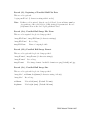
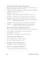
Executive summary
ShipMo3D Version 3.0 User Manual for Creating Ship
Models
Kevin McTaggart; DRDC Atlantic TM 2011-307; Defence R&D Canada – Atlantic;
December 2011.
Introduction: Ship motions influence the performance and safety of naval personnel
and systems. Consequently, ship motion predictions are often used to support ship
design and operation. Frequency domain predictions are computationally efficient
and suitable for ships travelling with steady speed and heading in moderate seaways.
Time domain analysis is required to model motions if a ship is freely maneuvering or
in a heavy seaway.
Principal Results: ShipMo3D is an object-oriented library with associated user applications for predicting ship motions in calm water and in waves. Motion predictions
are available in both the frequency domain and the time domain. For predictions in
the time domain, the ship can be freely maneuvering in either calm water or in
waves. This report serves as a user manual for creating ship models using Version 3.
A companion report provides a user manual for predicting ship motions in the time
and frequency domains using created ship models. ShipMo3D Version 3 introduces
capabilities for modelling U-tube tanks and sloshing tanks.
Significance of Results: ShipMo3D continues to be suitable for providing predictions of ship motions in waves. These simulations can be used for various applications,
including engineering analysis, operations analysis, and training.
Future Plans: ShipMo3D Version 3 will be incorporated into simulations modelling
naval platform systems using the High Level Architecture.
DRDC Atlantic TM 2011-307
iii
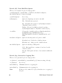
Sommaire
ShipMo3D Version 3.0 User Manual for Creating Ship
Models
´
Kevin McTaggart ; DRDC Atlantic TM 2011-307 ; R & D pour la defense
Canada –
´
Atlantique ; decembre
2011.
Introduction : Les mouvements de navires ont une influence sur le rendement et la
s´ecurit´e du personnel et des syst`emes navals. Par cons´equent, les pr´evisions des mouvements de navires sont souvent utilis´ees en appui `a la conception et a` l’exploitation
des navires. Les pr´evisions du domaine fr´equentiel sont efficaces pour l’´evaluation
et conviennent aux navires qui naviguent a` vitesse continue et font cap dans des
voies maritimes moyennement occup´ees. L’analyse du domaine temporel est requise
pour mod´eliser les mouvements si un navire manœuvre librement ou dans une voie
maritime tr`es occup´ee.
R´
esultats principaux : ShipMo3D est une biblioth`eque objet avec applications
utilisateur connexes permettant de pr´evoir les mouvements de navires en eau calme
et dans les vagues. Les pr´evisions des mouvements sont disponibles dans le domaine
fr´equentiel et dans le domaine temporel. Pour les pr´evisions dans le domaine temporel,
le navire peut manœuvrer librement en eau calme ou dans les vagues. Le pr´esent
rapport sert de manuel de l’utilisateur pour la cr´eation de mod`eles de navires en
utilisant la version 3. Un rapport d’accompagnement fournit un manuel de l’utilisateur
pour les pr´evisions des mouvements de navires dans le domaine temporel et dans le
domaine fr´equentiel, en utilisant des mod`eles de navires d´ej`a cr´e´es. La version 3 du
logiciel ShipMo3D introduit des capacit´es permettant de mod´eliser des citernes a` tube
en U et des citernes a` ballottement.
Importance des r´
esultats : ShipMo3D convient toujours pour la pr´evision des
mouvements de navires dans les vagues. Les simulations peuvent ˆetre utilis´ees pour
diff´erentes applications, y compris l’analyse technique, l’analyse des op´erations et la
formation.
Travaux ult´
erieurs pr´
evus : La version 3 du logiciel ShipMo3D sera int´egr´ee `a des
simulations mod´elisant des syst`emes de plate formes navales a` l’aide de l’architecture
de haut niveau.
iv
DRDC Atlantic TM 2011-307
Table of contents
Abstract . . . . . . . . . . . . . . . . . . . . . . . . . . . . . . . . . . . . . . .
i
R´esum´e . . . . . . . . . . . . . . . . . . . . . . . . . . . . . . . . . . . . . . .
i
Executive summary . . . . . . . . . . . . . . . . . . . . . . . . . . . . . . . . .
iii
Sommaire . . . . . . . . . . . . . . . . . . . . . . . . . . . . . . . . . . . . . .
iv
Table of contents . . . . . . . . . . . . . . . . . . . . . . . . . . . . . . . . . .
v
List of tables . . . . . . . . . . . . . . . . . . . . . . . . . . . . . . . . . . . .
viii
List of figures . . . . . . . . . . . . . . . . . . . . . . . . . . . . . . . . . . . .
ix
1 Introduction . . . . . . . . . . . . . . . . . . . . . . . . . . . . . . . . . . .
1
2 New Features for ShipMo3D Version 3 . . . . . . . . . . . . . . . . . . . .
1
2.1
High Frequency Approximation for Evaluating Retardation Functions
2
2.2
Modelling of U-tube Tanks for Roll Stabilization . . . . . . . . . . .
2
2.3
Modelling of Sloshing in Tanks with Free Surfaces . . . . . . . . . .
2
2.4
Application SM3DSeakeepSeawayFromRaos for Predicting Motions
in a Seaway Using Input Response Amplitude Operators . . . . . . .
3
2.5
Prediction of Motion Sickness Incidence in the Frequency Domain .
3
2.6
Output of Motion Response Amplitude Operators for Operability
Analysis Using SHIPOP2 . . . . . . . . . . . . . . . . . . . . . . . .
3
3 Overview of Using ShipMo3D for Creating a Model of a Ship for
Predicting Motions . . . . . . . . . . . . . . . . . . . . . . . . . . . . . . .
4
4 Coordinate Systems . . . . . . . . . . . . . . . . . . . . . . . . . . . . . . .
7
5 Panelling of the Ship Hull – SM3DPanelHull . . . . . . . . . . . . . . . . .
10
5.1
Hull Description Using a Patch Hull File . . . . . . . . . . . . . . .
11
5.2
Control of Panelling of the Hull
. . . . . . . . . . . . . . . . . . . .
15
6 Radiation and Diffraction Computations – SM3DRadDif . . . . . . . . . .
17
DRDC Atlantic TM 2011-307
v
7 Panelling of a Sloshing Tank – SM3DPanelSloshTank . . . . . . . . . . . .
20
8 Radiation Computations for a Sloshing Tank – SM3DRadSloshTank . . . .
23
9 Building of Ship Model – SM3DBuildShip . . . . . . . . . . . . . . . . . .
26
9.1
Hull Viscous Forces . . . . . . . . . . . . . . . . . . . . . . . . . . .
28
9.2
Hull Maneuvering Forces . . . . . . . . . . . . . . . . . . . . . . . .
28
9.3
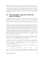
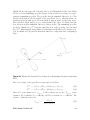
Ship Appendages – Bilge Keels, Static Foils, Skegs, and Rudders . .
29
9.4
Propellers (Non-azimuthing) . . . . . . . . . . . . . . . . . . . . . .
31
9.5
Rudder-Propeller Interaction Coefficients . . . . . . . . . . . . . . .
32
9.6
Azimuthing Propellers . . . . . . . . . . . . . . . . . . . . . . . . . .
32
9.7
U-tube Tanks and Sloshing Tanks . . . . . . . . . . . . . . . . . . .
34
9.8
Computation of Ship Propeller RPM for Specified Ship Speeds . . .
34
10 Conclusions . . . . . . . . . . . . . . . . . . . . . . . . . . . . . . . . . . .
38
References . . . . . . . . . . . . . . . . . . . . . . . . . . . . . . . . . . . . . .
39
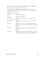
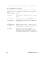
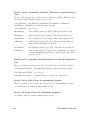
Symbols and Abbreviations . . . . . . . . . . . . . . . . . . . . . . . . . . . .
42
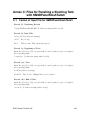
Annex A: Files for Panelling the Hull with SM3DPanelHull3 . . . . . . . . . .
47
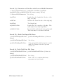
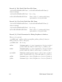
A.1
Format of Input File for SM3DPanelHull3 . . . . . . . . . . .
47
A.2
Format of Input PatchHull File . . . . . . . . . . . . . . . . .
62
A.3
Sample Input File for SM3DPanelHull3 . . . . . . . . . . . .
66
A.4
Sample Patch Hull Input File for SM3DPanelHull3 . . . . . .
67
A.5
Sample Output File for SM3DPanelHull3 . . . . . . . . . . .
77
Annex B: Files for Radiation and Diffraction Computations with SM3DRadDif3 83
B.1
vi
Format of Input Radiation and Diffraction File for
SM3DRadDif3 . . . . . . . . . . . . . . . . . . . . . . . . . .
83
B.2
Sample Input File for SM3DRadDif3 . . . . . . . . . . . . . .
96
B.3
Sample Output File for SM3DRadDif3 . . . . . . . . . . . . .
97
DRDC Atlantic TM 2011-307
Annex C: Files for Panelling a Sloshing Tank with SM3DPanelSloshTank3 . . 109
C.1
Format of Input File for SM3DPanelSloshTank3 . . . . . . . 109
C.2
Format of Input PatchSloshTank File . . . . . . . . . . . . . 124
C.3
Sample Input File for SM3DPanelSloshTank3 . . . . . . . . . 128
C.4
Sample Patch Tank Input File for SM3DPanelSloshTank3 . . 129
C.5
Sample Output File for SM3DPanelSloshTank3 . . . . . . . . 131
Annex D: Files for Sloshing Tank Radiation Computations with
SM3DRadSloshTank3 . . . . . . . . . . . . . . . . . . . . . . . . . 137
D.1
Format of Input Sloshing Tank Radiation File for
SM3DRadSloshTank3 . . . . . . . . . . . . . . . . . . . . . . 137
D.2
Sample Input File for SM3DRadSloshTank3 . . . . . . . . . . 149
D.3
Sample Output File for SM3DRadSloshTank3 . . . . . . . . . 150
Annex E: Files for Building Ship with SM3DBuildShip3 . . . . . . . . . . . . 161
E.1
Format of Input Ship File for SM3DBuildShip3 . . . . . . . . 161
E.2
Sample Input File for SM3DBuildShip3 . . . . . . . . . . . . 220
E.3
Sample Output File for SM3DBuildShip3 . . . . . . . . . . . 223
Document Control Data . . . . . . . . . . . . . . . . . . . . . . . . . . . . . . 233
DRDC Atlantic TM 2011-307
vii
List of tables
Table 1:
Command Line Options for ShipMo3D Applications . . . . . . . .
6
Table 2:
SM3DPanelHull Summary . . . . . . . . . . . . . . . . . . . . . .
10
Table 3:
Guidelines for Ordering of Offsets and Hull Lines for Different
Hull Portions . . . . . . . . . . . . . . . . . . . . . . . . . . . . .
13
Table 4:
SM3DRadDif Summary . . . . . . . . . . . . . . . . . . . . . . . .
17
Table 5:
SM3DPanelSloshTank Summary . . . . . . . . . . . . . . . . . . .
20
Table 6:
SM3DRadSloshTank Summary . . . . . . . . . . . . . . . . . . . .
23
Table 7:
SM3DBuildShip Summary . . . . . . . . . . . . . . . . . . . . . .
26
viii
DRDC Atlantic TM 2011-307
List of figures
Figure 1:
Earth-Fixed Coordinate System . . . . . . . . . . . . . . . . . . .
8
Figure 2:
Translating Earth Coordinate System . . . . . . . . . . . . . . . .
8
Figure 3:
Sea Direction Relative to Ship . . . . . . . . . . . . . . . . . . . .
9
Figure 4:
Panelled Wet Hull of Generic Frigate . . . . . . . . . . . . . . . .
10
Figure 5:
Patch Hull Lines of Generic Frigate . . . . . . . . . . . . . . . . .
12
Figure 6:
Patch Hull Surfaces of Generic Frigate . . . . . . . . . . . . . . .
12
Figure 7:
Hull Line within Patch Hull File, View from Aft . . . . . . . . . .
13
Figure 8:
Profile of Patch Representing the Main Portion of Ship Hull, View
from Port Side . . . . . . . . . . . . . . . . . . . . . . . . . . . . .
14
Convention for Evaluating Hull Normal from Input Patch Data . .
14
Figure 10: Ship Vertical Coordinates, View from Starboard . . . . . . . . . .
15
Figure 11: Heave Added Mass and Damping for Generic Frigate . . . . . . .
18
Figure 12: Dimensions of Sloshing Tank with Rectangular Cross-Section . . .
21
Figure 13: Sloshing Tank with a Narrow Middle . . . . . . . . . . . . . . . .
22
Figure 14: Sway Sloshing Added Mass and Damping for Box with Length of
4 m, Width of 4 m, and Fluid Height of 2 m . . . . . . . . . . . .
24
Figure 15: Panelled Hull, Appendages, and Propellers of Generic Frigate
from SM3DBuildShip . . . . . . . . . . . . . . . . . . . . . . . . .
27
Figure 16: Appendage Root Location and Dihedral Angle, View from Aft . .
30
Figure 17: Dimensions for Static Foil or Rudder from Viewpoint
Perpendicular to Appendage . . . . . . . . . . . . . . . . . . . . .
30
Figure 18: Thrust and Normal Forces Acting on an Azimuthing Propeller in
Incident Flow . . . . . . . . . . . . . . . . . . . . . . . . . . . . .
33
Figure 19: Thrust Force Coefficient for Example Azimuthing Propeller . . . .
35
Figure 9:
DRDC Atlantic TM 2011-307
ix
Figure 20: Normal Force Coefficient for Example Azimuthing Propeller . . .
35
Figure 21: Aft View of U-tube Tank with Fluid Displacement Angle . . . . .
36
Figure 22: Aft View with ShipMo3D Input Dimensions for U-tube Tank . . .
37
x
DRDC Atlantic TM 2011-307
1
Introduction
This report describes the creation of ship models for ShipMo3D Version 3.0, an objectoriented library with associated applications for simulation of a ship in waves. A companion report [1] is the user manual for predicting motions in the time and frequency
domains using ShipMo3D Version 3.0. For each ShipMo3D application, user input
is read from an ASCII input file. Each application produces an ASCII output file,
and many applications also produce graphical output. The ShipMo3D graphical user
interface (GUI), ShipMo3D30.exe, can be used to interactively prepare input data,
launch applications, and view output results.
Several reports describe the theory behind ShipMo3D, and also give verification and
validation of ShipMo3D results. References 2 and 3 describe the prediction of hull hydrodynamic forces. The modelling of seaways is described in Reference 4. Reference 5
covers appendage and viscous forces, which are important for predicting lateral plane
motions. The extension of ShipMo3D to freely maneuvering ships is described in
Reference 6, with refinements to maneuvering forces given in Reference 7. ShipMo3D
Version 3.0 introduces modelling of U-tube tanks [8] and sloshing in tanks with free
surfaces [9]. Reference 10 gives validation results for Version 3.0 of ShipMo3D.
Section 2 of this report describes features that are new for Version 3 of ShipMo3D.
Section 3 gives an overview of creating ship models that can subsequently be used
for motion predictions. Section 4 describes coordinate systems used for motions
and ship geometry. Sections 5, 6, 7, 8, and 9 describe the ShipMo3D applications SM3DPanelHull, SM3DRadDif, SM3DPanelSloshTank, SM3DRadSloshTank,
and SM3DBuildShip, which are used to build models of the ship hull geometry, hull
radiation and diffraction properties, sloshing tank geometry, sloshing tank radiation
properties, and ship including appendages. Final conclusions are given in Section 10.
Annexes at the end of the report give input file descriptions and sample input and
output files for the ShipMo3D applications.
2
New Features for ShipMo3D Version 3
ShipMo3D Version 3 supercedes Version 2 [11, 12]. Version 3 includes several major
enhancements, and also has many minor code improvements.
DRDC Atlantic TM 2011-307
1
2.1
High Frequency Approximation for Evaluating
Retardation Functions
When computing wave radiation damping forces in the time domain, retardation
functions are used [3]. The retardation functions are computed from wave radiation
damping coefficients evaluated in the frequency domain. ShipMo3D Version 3 uses
the following high frequency approximation for damping coefficients when computing
retardation functions within SM3DBuildShip:
Bij (ωe ) = Bij (ωe∗ ) exp (−2ωe /ωe∗ + 2) for ωe ≥ ωe∗
(1)
where Bij is frequency domain damping for motion modes i and j, ωe is wave encounter frequency, and ωe∗ is the highest encounter frequency for damping coefficients
used for computing retardation functions. The above approximation helps to eliminate oscillatory behaviour of retardation functions at the maximum frequency ωe∗ .
The following high frequency approximation from Nam et al. [13] was originally considered for implementation in ShipMo3D:
∗ 2
ωe
∗
for ωe ≥ ωe∗
(2)
Bij (ωe ) = Bij (ωe )
ωe
Equation (1) provides faster decay of damping coefficients at higher frequencies, and
appears to give better modelling of actual behaviour. Note that Equations (1) and
(2) give similar behaviour of the variation of damping coefficients with encounter
frequency when encounter frequency ωe is approximately equal to the maximum frequency ωe∗ .
2.2
Modelling of U-tube Tanks for Roll Stabilization
ShipMo3D can now model U-tube tanks for roll stabilization. Hydrodynamic forces
are evaluated using the method of Lloyd [14], with ShipMo3D implementation described in Reference 8. Dimensions for U-tube tanks are given as input to SM3DBuildShip.
2.3
Modelling of Sloshing in Tanks with Free Surfaces
ShipMo3D can now model sloshing in tanks with free surfaces. Examples of such
tanks are cargo tanks and flume tanks for roll stabilization. SM3DPanelSloshTank
builds a panelled representation of a sloshing tank. SM3DRadSloshTank computes
sloshing hydrodynamic forces in the frequency domain based on the approaches of
Malenica et al. [15] and Newman [16], with the ShipMo3D implementation described
in Reference 9. Output sloshing tank data from SM3DRadSloshTank can be used as
input to SM3DBuildShip when building ship models.
2
DRDC Atlantic TM 2011-307
2.4
Application SM3DSeakeepSeawayFromRaos for
Predicting Motions in a Seaway Using Input
Response Amplitude Operators
The new application SM3DSeakeepSeawayFromRaos [1] can predict motions in the
frequency domain for a ship travelling in a seaway defined in earth-fixed axes. SM3DSeakeepSeawayFromRaos reads pre-computed motion response amplitude operators
(RAOs) which can be computed by SM3DSeakeepRandom. SM3DSeakeepSeawayFromRaos runs faster than SM3DSeakeepSeaway [1], and is suitable for applications
such as real-time operator guidance.
2.5
Prediction of Motion Sickness Incidence in the
Frequency Domain
When predicting ship motions in the frequency domain, the applications SM3DSeakeepRandom, SM3DSeakeepSeaway, and SM3DSeakeepSeawayFromRaos can now
predict motion sickness incidence. Colwell [17] describes the approaches used for
evaluating motion sickness incidence.
2.6
Output of Motion Response Amplitude Operators
for Operability Analysis Using SHIPOP2
The frequency domain application SM3DSeakeepRandom [1] can now write motion
response amplitude operators in SHIPMO7 ASCII post-processing format, which can
be used as input for operability analysis using SHIPOP2 [18].
DRDC Atlantic TM 2011-307
3
3
Overview of Using ShipMo3D for Creating
a Model of a Ship for Predicting Motions
The following applications can be used when creating a ShipMo3D model of a ship:
SM3DPanelHull: Develops a model of the hull surface represented using triangular
and quadrilateral panels. Also computes hydrostatic properties for submerged
portion of hull.
SM3DRadDif: Computes hydrodynamic added mass and radiation damping for
ship hull. Also computes forces due to incident and diffracted waves.
SM3DPanelSloshTank: Develops a model of the the surface of a sloshing tank
represented using triangular and quadrilateral panels.
SM3DRadSloshTank: Computes sloshing tank hydrodynamic added mass and radiation damping.
SM3DBuildShip: Builds a model of the ship including all components relevant to
predicting ship motions.
ShipMo3D: The ShipMo3D graphical user interface (ShipMo3D30.exe for Version
3.0) can be used to prepare input data, launch the above applications, and view
results.
SM3DPanelHull creates a panel representation of the wetted hull surface based on input hull surface coordinates and load condition data. SM3DPanelHull can optionally
produce a panel representation of the dry hull surface, which is required for nonlinear simulations that consider the variation of the ship wetted surface with time.
Ship hydrostatics and parameters for panel checking are included in output from
SM3DPanelHull. Section 5 describes SM3DPanelHull in greater detail.
The wet panelled hull produced by SM3DPanelHull is used as input for radiation
and diffraction computations in SM3DRadDif. SM3DRadDif produces a database
file that can be used for subsequent ship motion computations. The output from
SM3DRadDif should ideally encompass all combinations of ship speed, wave heading, and wave frequency that a ship will encounter. Typical computations encompassing all relevant combinations can require 2-3 hours; however, once a radiation and
diffraction database has been produced it can be used for simulations in a variety of
conditions. Section 6 describes SM3DRadDif in greater detail.
SM3DPanelSloshTank creates a panel representation of the wetted surface of the
interior of a tank containing fluid. Output from SM3DPanelSloshTank can be used
4
DRDC Atlantic TM 2011-307
for subsequent sloshing force computations. Section 8 describes SM3DRadSloshTank
in greater detail.
The wet panelled tank interior produced by SM3DPanelSloshTank is used as input
for sloshing radiation computations in SM3DRadSloshTank. SM3DRadSloshTank
produces a database file that can be used for subsequent ship motion computations.
The output from SM3DRadSloshTank should ideally encompass the full range of
encounter frequencies that will influence ship motions. SM3DRadSloshTank typically
requires less than one hour to run. Section 8 describes SM3DRadSloshTank in greater
detail.
SM3DBuildShip builds a model of a ship for ship motion computations. The radiation
and diffraction database file produced by SM3DRadDif is a key input component
to SM3DBuildShip. If the ship includes sloshing tanks, then one or more sloshing
radiation database files produced by SM3DRadSloshTank can be given as inputs.
Other program inputs include descriptions of appendages (bilge keels, rudders, foils,
and skegs), propellers, U-tube tanks, and hull resistance. SM3DBuildShip can build a
ship model for either simulation in the time domain or for predictions in the frequency
domain using the applications described in Reference 1.
The above ShipMo3D applications use 3 main types of files. User input data are
read from input files with names ending with “.inp”. Application output data for review by the user are written to output files with names ending with “.out”. Transfer
of data between applications is typically done using files in .NET binary serialization format, with names ending with “.bin”. For files representing a seaway, .NET
XML serialization format is used to facilitate utilization by other applications such
as visualizers.
Each ShipMo3D application has default file names for input and output. Prefixes can
be added to default file names by typing “-p PREFIX” as a command line option,
where PREFIX is the specified file name prefix (e.g., the ship name). Alternatively,
full input and output file names can be specifed on the command line. Input file
names can be specified by typing “-i INFILE” as a command line option, where
INFILE is the specified input file name. Similarly, output file names can be specified
by typing “-o OUTFILE” as a command line option, where OUTFILE is the specified
output file name. The command line option “-h” shows any command line arguments
associated with a ShipMo3D application. The command line option “-e” specifies that
exceptions that occur during program execution should be fully written to the console.
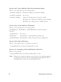
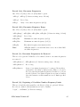
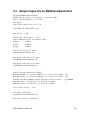
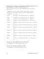
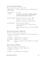
Table 1 summarizes command line options.
ShipMo3D user input files are in ASCII format. Each input line typically begins with
a tag denoting the contents of the input line. Comments can be inserted into a file
using the character “#” to denote a comment line or the beginning of a comment
after other input on a line. An exclamation mark “!” denotes that an input line is
DRDC Atlantic TM 2011-307
5
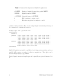
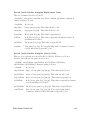
Table 1: Command Line Options for ShipMo3D Applications
-p PREFIX
Input and output file names have prefix PREFIX
-i INFILE
Input file name is INFILE
-o OUTFILE
Output file name is OUTFILE
-h
Help is written to output console
-e
Execution exceptions are written to console
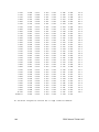
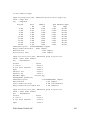
continued on the next line. Here is some sample input demonstrating the usage of
the comment and continuation characters:
# Sample input from a patch hull file.
begin hullLine
station 0
yOffsets
0.000 0.059 0.069 0.091 0.121 0.164 0.218 0.282
0.357 0.440 0.532 0.633 0.740 0.857 0.981 1.113
1.250 1.389 1.530 1.671 1.812 1.950 2.086 2.217
2.342 2.509 2.633 2.739 2.751
zOffsets
4.427 4.700 4.977 5.253 5.530 5.806 6.083 6.359
6.636 6.912 7.189 7.465 7.742 8.018 8.295 8.571
8.848 9.124 9.401 9.677 9.954 10.230 10.507 10.783
11.060 11.462 11.793 12.125 12.166
end hullLine
!
!
!
!
!
!
ShipMo3D applications include capabilities for plotting various entities, such as a
panelled hull geometry or results of radiation computations. These plots can be
saved as images in png or jpg formats.
Detailed input formats and sample input and output files are given in Annexes A to
E.
6
DRDC Atlantic TM 2011-307
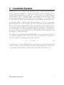
4
Coordinate Systems
ShipMo3D uses both earth-fixed and translating earth coordinate systems. Figure 1
shows a ship in an earth-fixed coordinate system. The location of the ship centre of
gravity in the horizontal plane is given by xf , y f . The direction ν of incident waves
is given using a “from” convention, with 0◦ representing waves from north and 90◦
representing waves from east. Ship heading χ is given using a “to” convention, with
0◦ representing the ship heading north and 90◦ representing the ship heading east.
A translating earth coordinate system, shown in Figure 2, is used for representing
ship motions in heave, roll, and pitch, and also for frequency domain applications.
Heave η3 is the vertical displacement (+ upward) of the ship centre of gravity relative
to its position when the ship is in calm water; thus, the mean heave is typically near
zero. Ship pitch η5 of a freely maneuvering ship is given relative to its position at
heading χ, and ship roll η4 is given relative to the instantaneous heading angle χ and
pitch angle η5 of the moving ship.
Wave diffraction computations using SM3DRadDif are based on relative sea direction
βs as shown in Figure 3 (180◦ for head seas, 90◦ for seas from port). Relative sea
direction is related to ship heading and wave heading by:
βs = ν + 180◦ − χ
(3)
For deflections of rudders, ShipMo3D uses a convention of positive deflection when
counter-clockwise as viewed from inside the hull. Consequently, positive deflection of
a typical ship rudder pointing downward will cause a ship to turn starboard.
DRDC Atlantic TM 2011-307
7
xf
..
.........
.....................
..
.......
..... .
.
.
.
...........
.
.....
.. ... ..
.....
...
.....
..
.....
....
...
....
.
.
..
.
.
....
..
...
.....
..
...
.....
.....
...............
...
.....
...............
.
.
.
.
...
.
.........
.
........ ...
.....
...
.......
.....
...
...
.....
...
. ............... .........
..............
...
...
..
...
.
.....
...
...
.....
.....
...
.
.....
.
.
.
.
......................... ...
..
............
.....
...
.
.....
...
... ........
...
. ...........
.
.
...
.. ....... ....
...
...
..
...
... ............
...
... ........
.
...
.
.
.
.
.
.
..
..
...............................................................................................................................................................
..
.
..
.
..
..
.
.
.
.
.
.
...
.
.
.
.
...
...
...
...
....
...
......
.....................................................
.
. .
...
...
...
...
.
.
...
.........
..............
......
Ship
.........
.... ....
.
.
. .
........ ......
.
χ
ν
yf
•
β
Sea
Figure 1: Earth-Fixed Coordinate System
z
.................................................
...
..
.
y ..
•CG .....
..
...
..η4
.
...............................................
.
......
.........
..
...
...
....
...
...
...
...
..
...
.
........................................................
...
.........................................................................................
.
.
.
............
...
..................................
η3 ... z
....
........
.............................................................................................................................................................................................................
....
..
...
..
η5 .............. ........ CG ..... x
...
.
..
.
.
.
.
.
.
.
.
.
.
.
.
.
.
.
.
.
.
.
.
.
.
.
.
.
.
.
.
.
.
.
.
.
.
.
.
.
.
.
.
.
.
.
.
.
...
............................................................................................................................•.......................................................................................................................................................................................................
..................
...
..
.....
...
....
.......
.......................
..
...
.
.
.......................................................................................................................................................................
η2 ... y
...........................................................................................................................................................................................
........
..
...
...
......
...
...
...
..
.
.
.
......
x
...
...
.....
..............
.
.....
.
.
.
.
.
.
.
.
.
.
.
.
.
.
.
.
.
.
.
.
.
.
.
.
.
.
.
.
.
.
.
.
.
.
.....
•
...
..
....
...
.
η
.
.
1
...
.
...
η
.
.
.....
6.......
..
.......
...
..............................
.......
........................................................................................................................................................................
Figure 2: Translating Earth Coordinate System
8
DRDC Atlantic TM 2011-307
...........................................................................................................................................................................
........
...
......
....
...... ...Ship
...
. .........
.............................................................................................................................................................................
.•
.
.....
..........................................
.
...
.
.
.
.
.
.
.
.
.
...
.
.
.
.
.
.
.
.
.
.
...
....
...
....
............
.....
..... ............................
βs
...
........
....
.
.
.
.
.....
.
.
.
.
.
.
.
.
.
.
.
.
.
.
.
.
.
.
.
.......................................................................................................................................................
Sea
..
.....
.....
.....
.....
.
.
.
....
.....
.....
.....
.....
.
.
.
.
....
.....
.....
.....
............
.
.
................
......
Figure 3: Sea Direction Relative to Ship
DRDC Atlantic TM 2011-307
9
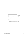
5
Panelling of the Ship Hull – SM3DPanelHull
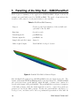
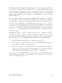
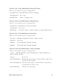
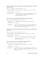
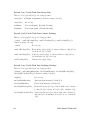
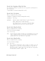
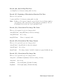
Table 2 gives a summary of the application SM3DPanelHull. Figure 4 shows an
example wet panel hull created by SM3DPanelHull. The panel colours indicate the
elevation of the centroid of each panel relative to the waterline.
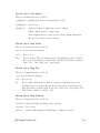
Table 2: SM3DPanelHull Summary
Purpose:
Creates a panel representation of the wet hull, and
optionally of the dry hull.
Run time:
Several seconds.
Default input file:
panelHull3.inp
Default output file:
panelHull3.out
Sample files and file format:
Annex A
Other required input:
Patch hull file developed by user.
Figure 4: Panelled Wet Hull of Generic Frigate
Like all ShipMo3D applications, SM3DPanelHull reads user input from a file. The
format of the main SM3DPanelHull input file is given in Annex A.1. SM3DPanelHull
also reads data from a patch hull file, which has hull coordinate data. Annex A.2
describes the format of the patch hull file. The patch hull file is a reference description
of the hull geometry, while the main input file is used to control how panels are
generated to model the hull geometry. Ideally, the patch hull file only has to be
developed once, and then can be left as a permanent representation of the hull. In
10
DRDC Atlantic TM 2011-307
contrast, the main input file can vary depending on the ship loading condition and
how the user wants the hull to be panelled.
5.1
Hull Description Using a Patch Hull File
The patch hull file models the hull as a series of patches, with a patch being a
continuous surface. For example, an ellipsoid could be modelled by a single patch.
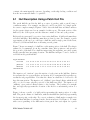
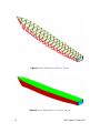
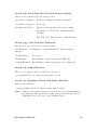
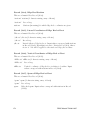
As a more complex example, Figures 5 and 6 show the hull lines and fitted surfaces
for the generic frigate used as an example for this report. The main portion of the
hull is red, the deck is green, and the transom consists of blue and cyan portions.
Each patch is represented by a series of successive hull lines. A hull patch must have
at least 2 hull lines. Each hull line must have at least 1 point. For example, a patch
representing a bulbous bow could have a hull line with a single point at the front,
followed by additional hull lines each having several points.
Figure 7 shows an example of a hull line on the main portion of the hull. The ship is
assumed to be symmetric about the centreline; thus, offset points are only given for
the port side of the hull. For a hull line intersecting the waterline, successive points
should generally have increasing elevation. The hull line in Figure 7 can be described
as follows in the patch hull file:
begin hullLine
stations
yOffsets
zOffsets
end hullLine
8.0 8.0 8.0 8.0 8.0 8.0 8.0 8.0 8.0 8.0 8.0 8.0 8.0
0.0 0.6 1.2 2.3 3.0 3.7 4.0 4.2 4.4 4.5 4.7 4.8 4.9
0.3 0.4 0.5 0.8 1.1 1.5 1.9 2.3 2.9 3.5 4.3 5.4 6.5
The input record “stations” gives the station of each point on the hull line. Station
0 represents the fore perpendicular, and station 20 (or sometimes 10) typically represents the aft perpendicular. Note that the offsets on a hull line do not need to all
have the same station. The input record “yOffsets” gives lateral offsets, which should
all be >= 0.0 because only the port side of the hull is modelled. The input record
“zOffsets” gives vertical offsets relative to the baseline. The baseline is a straight
line, and typically represents the elevation of the keel for a substantial portion of a
ship.
Figure 8 shows a profile of a hull patch representing the main portion of a ship
hull. The patch consists of 6 hull lines, with the first hull line (index 0) representing
the foremost point on the ship. For correct evaluation of hull surface normals, it is
essential that hull lines be arranged in the direction indicated by Figure 9. To assist
with correct panelling of the hull surface from patch data, user input for a patch
DRDC Atlantic TM 2011-307
11
Figure 5: Patch Hull Lines of Generic Frigate
Figure 6: Patch Hull Surfaces of Generic Frigate
12
DRDC Atlantic TM 2011-307
..
........
........
.. .... ..
...
....
..
...
...
...
...
...
...
...
...
...
...
...
...
...
...
...
...
...
...
...
...
...
...
...
...
...
...
...
...
...
...
...
...
...
...
...
...
...
...
...
...
...
...
...
...
...
...
...
...
...
...
...
...
.
.
.
.
.
.
.
.
........................................................................................................................................................................................................................................................................................................................
..
zbl
i = n − 1 •....
...
...
...
..
i = n − 2 •....
...
...
...
..
•.....
...
...
.
•....
... Design Waterline
...
•..
...
...
•...
...
•...
.....
•........
.........
•.............
.....•..........
...........
i = 2 .........•....................................
•i=0
i=1
y
Baseline
Figure 7: Hull Line within Patch Hull File, View from Aft
includes valid ranges of normal components. ShipMo3D uses a convention of hull
normals pointing outward from the hull.
In summary, the following should be observed when creating a patch hull file:
• For non-horizontal hull lines, the order of offset points should go from lower to
higher elevation.
• The order of successive hull lines must be given to satisfy the hull normal
convention of Figure 9.
Table 3 gives guidelines for patch representations of different parts of a hull.
Table 3: Guidelines for Ordering of Offsets and Hull Lines for Different Hull Portions
Main hull surface
Offsets on a hull line go from keel to port deck edge.
Successive hull lines go from bow to stern.
Deck
Offsets on a hull line go from port deck edge to centreline.
Successive hull lines go from bow to stern.
Transom
Offsets on a hull line go from bottom to deck edge.
Successive hull lines go from port edge to centreline.
DRDC Atlantic TM 2011-307
13
Hull line n − 1
Hull line 2
Hull line 1
Hull line 0
•.......................... ....... ....... ....... .......•...... ....... ....... ....... ....... ....... ....•........ ....... ....... ....... ....... ....... •............ ....... ....... ....... ....... .......•............. ....... ....... ....... ....... .....•.......
.
.
.
.
.
.....
.....
•........
•........
•........
•........
•........
.....
.....
.....
.
.
.
.
.....
•........
•.......
•.......
•.......
•.......
.....
.....
.
.
.
.
.
.
.
.
.
.
.
Bow .........
Stern •.....
•.......
•.......
•.......
•.......
.....
....
.....
.
.
.
.
.....
.
.
.
.
.
..... •
•........
•......
•......
•......
..... ....
..... ..
.
.
.
.
......
•...
•...
•.
•...
•...
Baseline
Figure 8: Profile of Patch Representing the Main Portion of Ship Hull, View from
Port Side
t - direction of successive points on a hull line
......
.........
..........
...
....
..
...
...
...
...
...
...
...
...
...
...
...
...
...
...
...
...
...
...
...
...
......
.
.......................................................................................................................................................
.
.
.
.
...
.
.
.
.
...
.
.
.
.
.....
....
.....
.....
.....
.
.
.
.
.....
.....
.....
.....
....
.
.
.
.
.....
.....
.....
.....
.....
.
.
.
....
.....
.....
........
....................
.
.
.
.
....
s - direction of successive hull lines
n - normal pointing outward from hull
Figure 9: Convention for Evaluating Hull Normal from Input Patch Data
14
DRDC Atlantic TM 2011-307
If the patch hull is going to be used to build both wet and dry panelled hulls, then
the patch hull should represent a closed volume. If only a wet panelled hull will be
built, then it is not necessary to enclose the dry portion of the hull.
Each input patch includes an optional input parameter to limit the maximum size of
panels representing the patch. This parameter can be useful for portions of the hull
surface with smaller curvature radii (e.g., bulbous bows) that require smaller panels
than the remainder of the hull surface.
5.2
Control of Panelling of the Hull
The main input file for SM3DPanelHull controls panelling of the hull described by
the patch hull file. SM3DPanelHull panels the wet hull, and optionally panels the
dry hull. Figure 10 shows the ship vertical coordinates. When giving the input load
condition, the user can provide one of the following sets of input data:
• draft of baseline at midships (draftBlMid) and trim of the baseline by the stern
(trimBlStern),
• displacement of the ship (dispTonnesInput) and the longitudinal distance from
the fore perpendicular to the the centre of gravity (distanceFPCGInput).
If the displacement and LCG are provided as input, then an iterative procedure is
used to determine the combination of draft and trim that produces a wet panelled
hull with the correct displacement and LCG.
.............................
z Midships
..............................................
.
.
.
.
.
.
.
.
.
.
.
.
.
.
.
.
.
.
.
.
.
.
.
.
.
.
.
.
.
.
.
.
.
.
.
.
.
.
.
.
.
.
....
..
.
...
......................
.
.
.
.
.
.
......... .......................................
.
.......................................
..
.............................................
.
.
x
.
.
.
.
.
.
.
.
.
.
...
.
.
.
.
.
.
.
.
.
.
.
.
.
.
.
.
.
.
.
.
.
.
.
.
.
.
.
.
.
.
.
.
.
.
.
.
.
.
.
.
.
.
.
.........
.
CG •..................................
.................... .
....................................................................................................................................................................................↑.|..................................................................................................................................................................................................................................................................................................................
......................................
............. .
|
.
..
↑|
............. .
...
..
.
...
.
KG draftBlMid
.....
........... .......
...
..
...
........
..
...
..
...
.......
...
.....
.......
.....
.....
.........
..........
.....
.....
......
.
.
.
.
.
.
.
.
.
|
.
↑
.
.
.
.
.
.
.
.
.
.
.
.
.
.
.
.
.
.
.
.
.
.
.
.
...
|
.............
.....
..
.
.
.
.
.
.
.
.
.
.
.
.
.
.
.
.
.
.
.
.
.
.
.
.
.
.
.
.
.
.
|
.
.
.
.
.
.
...
.....
.......
.....
.....
...
Baseline
↓|........................................................↓.................................................................
trimBlStern
.......
..
..........................................
...
..
.......
...
..
....
.......
..
...
..
.......
.
.
.
.
.
.
.
.
.
.
.
.
.
.
.
.
.
.
.
.
.
.
.
.
.
.
.
.
.
.
.
.
.
.
.
.
....
.
.
.
.......
.
..
...
.
..
..
.
.
.
.
.
.
.
.
.
.
.
.
.
.
.
.
.
.
.
.
.
.
.
....... ....
.
.
.
.
.
.
↓|
.
.
.
.
.
.
.
.
..................... ....... ....... ....... ....... ....... ....... ....... ....... ....... ....... ....... ....... ....... ....... ....... ....... ....... ....... ....... ....... ....... ....... ....... ....... ....... ....... ....... ....... ....... ....... ....... ....... ....... ....... ....... ....... .......
....... ....... .....
Figure 10: Ship Vertical Coordinates, View from Starboard
SM3DPanelHull fits smooth B-spline surfaces [19] to hull patches described by input
hull lines. If difficulties are encountered with a fitted surface (e.g., a normal vector
has unexpected direction or a y coordinate is less than zero) then these can often be
DRDC Atlantic TM 2011-307
15
resolved by dividing the patch in the vicinity of a hull line where the difficulties are
encountered.
The panel area limit areaPanelLimit is one of the most important input parameters for
SM3DPanelHull. For typical ship geometries, it is recommended that areaPanelLimit
be selected such that the wet portion of the hull surface is represented by 200-500
panels on the port side.
SM3DPanelHull can produce plots such as those given in Figures 4, 5, and 6. These
plots are very useful for checking the quality of a hull model. For the plots of the
patch hull surfaces and hull panels, the interior of the hull is black, which can be
useful for checking that hull normals are oriented correctly.
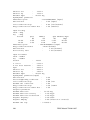
The SM3DPanelHull output file gives values for checking the quality of the panelled
hull mesh, such as normal ranges for hull patches. The output file also gives closure
errors for the hull in the x and z directions, such as the following from the sample
output file:
**** CHECK OF CLOSURE FOR COMBINED WET AND DRY HULL ****
Calculated properties for checking combined mesh of wet and dry hull
Closure error sum of area*nx
:
0.183245 m2
Closure error/approx front area :
0.001146
Closure error sum of area*nz
:
0.100498 m2
Closure error/approx top area
:
0.000110
The non-dimensional closure errors should typically be less than 0.01.
16
DRDC Atlantic TM 2011-307
6
Radiation and Diffraction Computations –
SM3DRadDif
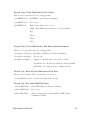
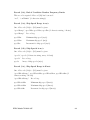
Table 4 gives a summary of the application SM3DRadDif, which computes hydrodynamic forces due to added mass, wave radiation damping, and wave excitation from
incident and diffracted waves. Computations are performed in the frequency domain;
however, results can be transformed to the time domain for subsequent computations. Due to the complexities of ship hydrodynamic computations, SM3DRadDif
is considered to be the most computationally intensive of ShipMo3D applications.
The approach used for computing hull hydrodynamic forces is described in detail in
References 2 and 3.
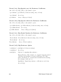
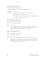
Table 4: SM3DRadDif Summary
Purpose:
Creates a database of added mass, radiation
damping, and wave excitation forces for the ship in
all conditions to be encountered in subsequent
motion computations.
Run time:
Several minutes without wave diffraction
computations.
Up to several hours with full wave diffraction
computations.
Default input file:
radDif3.inp
Default output file:
radDif3.out
Sample files and file format:
Annex B
Other required input:
Wet panelled hull created by SM3DPanelHull.
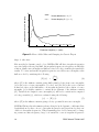
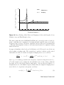
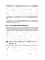
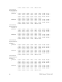
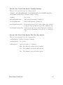
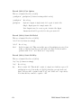
SM3DRadDif computes hull added mass and radiation damping for a range of encounter frequencies specified by user input. Figure 11 shows computed added mass
and damping for a naval frigate. The input encounter frequencies should be selected
such that the variation of added mass and damping with encounter frequency is
captured for all 6 degrees of freedom. The main output file from SM3DRadDif and
optional plot files of hydrodynamic coefficients can be examined to determine whether
a suitable range of encounter frequencies has been used. Both the output file and
plot files give non-dimensional coefficients with magnitude relative to the ship inertia
force amplitude during sinusoidal motion. At the highest encounter frequency, added
mass should approach its infinite frequency value and damping should approach zero.
For naval frigates, an encounter frequency range of 0.1, 0.2, . . ., 6.0 rad/s is suitable.
Froude scaling can be applied to determine suitable encounter frequency ranges for
DRDC Atlantic TM 2011-307
17
Heave added mass and damping
5
..
...................
Heave added mass A33 /4
.... ..
... .....
...
..... ..... ...
...
Heave damping B33 /(ωe 4)
...
4
...
...
...
...
...
...
3
...
..
........
.. .......
.. ........
2
......
...
......
..... .
......................... .........................................................
...
.......
.....
................................
...
.......................... ......................................
..
..
...
....
1 ..
....
.
.....
.... ..
...
... .....
..
..... ..... .....
..... ..... ..... ..... ..... ..... ..... ..... ..... ..... ..... ..... ..
..
... ..... .
0
0
2
4
6
Encounter frequency ωe (rad/s)
Figure 11: Heave Added Mass and Damping for Generic Frigate
ships of other sizes.
Like most hydrodynamic panel codes, SM3DRadDif will have irregular frequencies
associated with each wet panel hull. An irregular frequency is a frequency at which the
solution of hull source strengths and hull associated velocity potentials gives unreliable
results. To better understand irregular frequencies, note that source strengths on the
hull are solved by satisfying the following:
∂φ
[D] {σ} =
(4)
∂n
where [D] is the influence matrix giving hull normal velocity from source strengths,
{σ} is the vector of source strengths to be solved, and {∂φ/∂n} is the vector of known
normal velocities on the hull surface. At irregular frequencies, the solution of source
strengths {σ} is highly sensitive to variations in elements of the influence matrix
[D]. Variations in computed source strengths {σ} will lead to variations in computed
velocity potentials {φ}, which are evaluated using the following:
{φ} = [E] {σ}
(5)
where [E] is the influence matrix giving velocity potential from source strength.
SM3DRadDif uses lateral symmetry when solving for hydrodynamic coefficients; thus,
longitudinal modes have one set of irregular frequencies and lateral modes have another set of irregular frequencies. When examining plots of added mass and/or damping versus encounter frequency, large local variations occur at irregular frequencies.
18
DRDC Atlantic TM 2011-307
Similarly, an irregular frequency will usually have a large local increase in the condition number of matrix [D] from Equation (4). To prevent SM3DRadDif from using computations at irregular frequencies, user input can include threshold matrix
condition numbers indicating the presence of irregular frequencies. The threshold
matrix condition numbers can be determined by examining the results of an initial
SM3DRadDif run.
The most time consuming part of running SM3DRadDif is usually the evaluation
of wave diffraction forces. Note that wave diffraction forces should be evaluated for
all combinations of ship speed, heading, and wave frequency that a ship is likely to
encounter. For a naval frigate, an input ship speed range of 0, 5, 10, . . ., 40 knots
can be used. Note that the upper speed should include the influence of wave-induced
surge motion for a freely maneuvering ship. An input relative sea direction range of
0, 15, 30, . . ., 180 degrees is suitable for any ship. An input wave frequency range of
0.1, 0.2, 0.3, . . ., 2.0 rad/s usually is sufficient for the range of seaways encountered
by full-scale ships.
SM3DRadDif includes an option for suppressing diffraction computations. The primary purpose of this option is to permit checking for irregular frequencies before
proceeding with time-consuming diffraction computations. It is suggested that the
following sequence be used when using SM3DRadDif for a new wet panel hull:
1. Run SM3DRadDif with diffraction computations suppressed.
2. Check output for irregular frequencies and re-run SM3DRadDif with appropriate thresholds on matrix condition numbers.
3. Check revised output for irregular frequencies. If irregular frequencies still exist,
repeat step 2 with revised matrix condition numbers. If no irregular frequencies
remain, then run SM3DRadDif including diffraction computations.
As indicated above, SM3DRadDif can produce plots of non-dimensional hydrodynamic coefficients and matrix condition numbers. These plots are very useful when
checking for irregular frequencies.
DRDC Atlantic TM 2011-307
19
7
Panelling of a Sloshing Tank –
SM3DPanelSloshTank
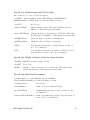
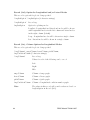
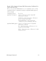
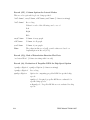
Table 5 gives a summary of the application SM3DPanelSloshTank.
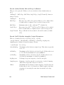
Table 5: SM3DPanelSloshTank Summary
Purpose:
Creates a panel representation of the interior of wet
sloshing tank, and optionally of the dry sloshing
tank.
Run time:
Several seconds.
Default input file:
panelSloshTank3.inp
Default output file:
panelSloshTank3.out
Sample files and file format:
Annex C
Other required input:
Patch sloshing tank exterior file developed by user.
This file is only required if the sloshing tank has a
complex shape.
Like all ShipMo3D applications, SM3DPanelSloshTank reads user input from a file.
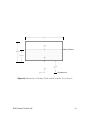
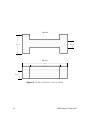
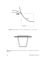
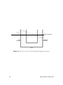
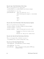
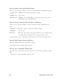
The format of the main SM3DPanelSloshTank input file is given in Annex C.1. Figure 12 shows dimensions for a simple sloshing tank with a rectangular cross-section.
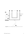
SM3DPanelSloshTank can easily model a box-shaped sloshing tank or a tank with a
narrow middle (see Figure 13) using minimal input.
For modelling of more complex tank geometries, SM3DPanelSloshTank can read data
for a patch representation of the tank, which is similar to the patch representation
of a hull read by SM3DPanelHull. Annex C.2 describes the format of the patch
sloshing tank file. To simplify creation of the patch sloshing tank input file, the file
uses a geometric convention to specify the exterior of the sloshing tank (i.e., normal
vectors point outward from the sloshing tank, which is the same convention as used
for a patch hull file). SM3DPanelSloshTank then performs the required conversion
to obtain the geometries of panels representing the interior of the tank.
Guidelines for panelling and the ship hull (see Section 5) are applicable to panelling
of a sloshing tank. It is recommended that a minimum of 200 panels be used to model
the wetted port side of a sloshing tank.
20
DRDC Atlantic TM 2011-307
←−−−−−−−−−−−−−−−−− wtank −−−−−−−−−−−−−−−−−→
↑|
|
|
|
|
↑
htank |
|
|
| h
f luid
|
|
|
|
|↓
↓
...........................................................................................................................................................................................................................
...
..
...
..
...
..
....... zf l
.........
..
.
...
...
...
.............................................................................................................................................................................................................................................................................................................................................
...................................................................................................................................•..................................................................................................................................... Mean fluid level
......................................................................................................................................................................................................................................................................
........................................................................................................................................................................................................................................................................
......................................................................................................................................................................................................................................................................
................................................................................................................................................z......t..........................................................................................................................
.............................................................................................................................................................................................................................................................................
.............................................................................................................................................................................................................................................................................
..........................................................................................................................................................................•...............................................................................................................................................................................
↑
|
|
y
...
......
........
....
...
..
.............................................
•
zbl
tank
zbl
|
|
↓ Ship baseline
Figure 12: Dimensions of Sloshing Tank with Rectangular Cross-Section
DRDC Atlantic TM 2011-307
21
Top view
↑|
|
|
|
|
Ltank
|
|
|
|
↓|
................................................................................................
................................................................................................
...........................................
...........................................
......................................................
......................................................
.
..........................................
.......................................................
..........................................
......................................................
.........................................................................................................................................................................................................................................................................................................................................................................................................................................................................
......................................................................................................................................................................................................................................................................................................................
........................................................................................................................................................................................................................................................................................................................
......................................................................................................................................................................................................................................................................................................................
..............................................................................................................................................................................................................................................................................................................................................................................................
......................................................
......................................................
........................................................
........................................................
......................................................
......................................................
........................................................
.......................................................
....................................................................
.....................................................................
↑
|
Lmiddle
|
↓
Aft view
hf luid
↑
|
|
|
|
↓
←−−−−−−−−−−−−−−−−−−−−− wtank −−−−−−−−−−−−−−−−−−−−−→
←−−−−−−−−−−−− wmiddle −−−−−−−−−−−−→
......................................................................................................................................................................................................................................................................
.
.
.
...
.............................................................................................................................................................................................................................................................................................................................................................................................................
...........................................................................................................................................................................................................................................................................................................................
...........................................................................................................................................................................................................................................................................................................................
.............................................................................................................................................................................................................................................
............................................................................................................................................................................................................................................
..........................................................................................................................................................................................................................................................................................................................
...........................................................................................................................................................................................................................................
...........................................................................................................................................................................................................................................................................................................................
.........................................................................................................................................................................................................................................................................................................................................................................................................................................................................................................
Figure 13: Sloshing Tank with a Narrow Middle
22
DRDC Atlantic TM 2011-307
8
Radiation Computations for a Sloshing
Tank – SM3DRadSloshTank
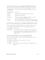
Table 6 gives a summary of the application SM3DRadSloshTank, which computes
hydrodynamic forces acting on a sloshing tank due to added mass and wave radiation
damping. Computations are performed in the frequency domain; however, results can
be transformed to the time domain for subsequent computations. The approach used
for computing sloshing hydrodynamic forces is described in detail in Reference 9.
Table 6: SM3DRadSloshTank Summary
Purpose:
Creates a database of added mass and radiation
damping forces for a sloshing tank.
Run time:
Approximately 1 hour.
Default input file:
radSloshTank3.inp
Default output file:
radSloshTank3.out
Sample files and file format:
Annex D
Other required input:
Wet panelled sloshing tank created by
SM3DPanelSloshTank.
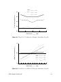
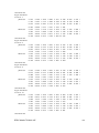
SM3DRadSloshTank computes sloshing tank added mass and radiation damping for
a range of encounter frequencies specified by user input. Figure 14 shows computed
added mass and damping for a box with length of 4 m, width of 4 m, and fluid height
of 2 m. The input encounter frequencies should be selected such that the variation
of added mass and damping with encounter frequency is captured for sloshing modes
that will influence the motions of the ship. When selecting the range of encounter
frequencies, it can be useful to consider the following analytical solution for sloshing
natural frequencies of a box of width wtank subject to sway motion [20]:
q
g λslosh
tanh(λn hf luid ) for n = 1, 2, . . .
(6)
ωnslosh =
n
nπ
λslosh
=
(7)
n
wtank
where n is the sloshing mode number. The sway sloshing added mass and damping
coefficients for a box-shaped tank will typically vary significantly in the vicinity of
sloshing frequencies for odd-numbered modes (n = 1, 3, 5, . . .). Computations suggest
that 0.02 ω1slosh is a suitable value for both the minimum encounter frequency and
encounter frequency increment, and that 4 ω1slosh is a suitable value for the maximum
encounter frequency.
DRDC Atlantic TM 2011-307
23
l
tank−f l
Atank−f
/mtank , B22
/(ωe mtank )
22
10
.
.....
...................
Added mass
......
......
..... ..... ...
.
damping
.....
... ...
..... ..
............
.
.
5
......
.........
................
... ......
... ...........
.
.
.. . .
..
...... ... ..... ...
........
....................................
.
.
.. .... ..
..
.
..... ... .... ............................................................................................................................................................................................................................
.....
... ......
0 ..... ..... ..... ..... ..... ....
.
... ...
... ...
... ..
... ...
... ...
... ...
... ...
......
......
..
-5
0
2
4
6
8
10
Encounter frequency ωe
Figure 14: Sway Sloshing Added Mass and Damping for Box with Length of 4 m,
Width of 4 m, and Fluid Height of 2 m
The main output file from SM3DRadSloshTank and optional plot files of hydrodynamic coefficients can be examined to determine whether a suitable range of encounter
frequencies has been used. Both the output file and plot files give non-dimensional
coefficients with magnitude relative to the static mass inertia force amplitude during
sinusoidal motion.
An approach similar to that developed by Malenica et al. [15] is used to model viscous
effects within a sloshing tank. The normal flow boundary condition on the wetted
tank walls is modified to include an empirical damping factor tank as follows:
∂φslosh
i tank slosh
j
= i ωe nfj l + p
φj
on St for j = 1 − 6
3
∂n
Vf luid
(8)
where φslosh
is sloshing potential in the frequency domain for ship motion mode j,
j
fl
nj is the normal vector pointing into the tank fluid, Vf luid is the volume of fluid in
the tank, and St is the wetted interior tank surface. Viscous effects are likely to be
insignificant at zero and infinite frequency limits; thus, the empirical damping factor
is modelled to be dependent on frequency as follows:
2
ωe
ˆ
ˆtank for ωe ≤ ωlower
(9)
tank (ωe ) =
ˆ
ωlower
24
DRDC Atlantic TM 2011-307
tank (ωe ) =
ˆ
ωupper
ωe
!2
ˆ
ˆtank for ωupper > ωupper
(10)
where ˆtank is the peak value of the damping factor, which is applicable at frequenˆ
ˆ
ˆ
ˆ
be selected
and ωupper
. It is suggested that ωlower
to ωupper
cies ranging from ωlower
such that they encompass the main sloshing frequencies of the tank, which can be
determined by examining the variation of added mass with frequency. For example,
ˆ
ˆ
ωlower
can be set to half of the first sloshing mode frequency and ωupper
can be set to
the maximum frequency used for sloshing computations.
Like SM3DRadDif, SM3DRadSloshTank can remove irregular frequencies caused by
ill-conditioned solutions for sloshing velocity potentials; however, work to date suggests that irregular frequencies will typically not occur when solving sloshing velocity
potentials.
Input for SM3DRadSloshTank includes the delay time increment ∆τ and delay time
maximum τmax for sloshing retardation functions, which are used for ship motion
computations in the frequency domain. Recommended values are ∆τ = 0.25/ω1slosh
and τmax = 120/ω1slosh . SM3DRadSloshTank includes an option for correcting sloshing retardation functions to account for the finite maximum delay time τmax . It is
recommended that this option be used, with care being taken to specify a sufficiently
large number of τmax to capture the essential behaviour of the retardation function.
The location of a sloshing tank on a ship is not specified as input for SM3DPanelSloshTank or SM3DRadSloshTank. Instead, the tank location is specified as input to
SM3DBuildShip. This approach allows the tank location on the ship to be changed
without re-running SM3DPanelSloshTank or SM3DRadSloshTank.
DRDC Atlantic TM 2011-307
25
9
Building of Ship Model – SM3DBuildShip
Table 7 gives a summary of application SM3DBuildShip, which creates a database of
all relevant ship properties used for computation of ship motions. Figure 15 shows
a sample view of a hull and appendages produced by SM3DBuildShip. SM3DBuildShip can build ship models for simulation in the time domain or for predictions in
the frequency domain.
Table 7: SM3DBuildShip Summary
Purpose:
Creates a database of ship properties influencing
hydrodynamic forces, including hull radiation and
diffraction, hull resistance, hull maneuvering, appendages, and propellers.
Run time:
Several seconds, or several minutes if propeller
RPMs are to be determined for specified ship speeds.
Default input file:
buildShip3.inp
Default output file:
buildShip3.out
Sample files and file format:
Annex E
Other required input:
Hull radiation and diffraction database created by
SM3DRadDif.
Dry panel hull file if nonlinear buoyancy and incident
wave forces will be used for ship motion predictions.
A dry panel hull file is among the optional input parameters for SM3DBuildShip.
Note that this option must be used if ship motion predictions with SM3DFreeMo will
include nonlinear buoyancy and incident wave forces.
SM3DBuildShip includes optional input for adjusting the metacentric height of the
ship. This parameter can be set to a negative value to model the influence of partially
filled tanks on roll stiffness. Note that such a correction for partially filled tanks is
only required if they have not been explicitly modelled as U-tube tanks or sloshing
tanks within ShipMo3D.
Input radii of gyration for roll, pitch, and yaw are given as values for the dry ship,
and do not include the influence of ship added mass. Estimates of radii of gyration
are as follows:
r44 ≈ 0.4 Bmax
r55 ≈ 0.25 L
r66 ≈ 0.25 L
26
(11)
(12)
(13)
DRDC Atlantic TM 2011-307
Figure 15: Panelled Hull, Appendages, and Propellers of Generic Frigate from
SM3DBuildShip
where r44 is roll radius of gyration, r55 is pitch radius of gyration, and r66 is yaw
radius of gyration. If the ship natural roll period is known but the ship roll gyradius
is unknown, it is recommended that SM3DBuildShip be run with several different
input gyradius values to determine which value produces the correct natural roll
period.
For time domain predictions of ship motions, wave radiation forces are evaluated using
retardation functions. The retardation functions are determined using transforms
of wave radiation forces in the frequency domain. SM3DBuildShip reads input for
the time interval and maximum value of retardation functions. The time interval
should be sufficiently fine to capture the variation of retardation functions, and the
maximum value should encompass the time when retardation functions approach
zero. For a naval frigate, a time interval of 0.2 s and maximum time of 20 s provide
good representation of retardation functions. Suitable values for other ships can be
estimated using Froude scaling as follows:
s
L
(14)
∆τ ≈ 0.05
g
s
L
τmax ≈ 5
(15)
g
where ∆τ is the time interval and τmax is the maximum time for retardation functions.
DRDC Atlantic TM 2011-307
27
9.1
Hull Viscous Forces
Viscous hull force input is given in the form of hull resistance coefficients for various
speeds, an eddy-making roll damping coefficient, and a lateral drag coefficient. References 5, 6 and 7 give further discussion of hull viscous forces. The hull resistance
force is evaluated as follows:
1
F1resist = − ρ U |U | Aw CDx (U )
2
(16)
where U is the ship speed, Aw is the wetted surface area, and CDx is the hull resistance
coefficient.
Hull eddy-making damping at zero speed is evaluated by:
Z
p
1
hull−eddy
hull 1
n24 y 2 + z 2 dS
F4
= − ρ |η˙ 4 | η˙4 Ceddy
2
2 Shull
(17)
hull
where Ceddy
is the hull eddy-making coefficient for roll, Shull is the wetted hull surface,
and n4 is the roll normal. At non-zero speed, a speed correction factor is applied.
The hull eddy-making coefficient has a default value of 1.17, the drag coefficient for
a flat plate moving perpendicular to flow. Note that hull eddy-making damping is
typically a small fraction of roll damping; thus, roll motion predictions are usually
not very sensitive to the value of the hull eddy-making coefficient.
ShipMo3D can model hull cross-flow drag as follows:
F2cross
Nseg
1 X cross
v
(xAy−i ) |v cross (xAy−i )| Ay−i CDy
ρ
=
2
i=1
(18)
where Nseg is the number of longitudinal segments along the hull for evaluating crossflow drag, v cross is cross-flow velocity, xAy−i is the x centroid of the profile area of
segment i, Ay−i is the profile area of segment i, and CDy is the hull cross-flow drag
coefficient. Within ShipMo3D, the hull cross-flow drag coefficient is often set to
zero because cross-flow drag forces are instead modelled using nonlinear maneuvering
coefficients. If nonlinear maneuvering coefficients are not used to model cross-flow
drag, then the cross-flow drag coefficient can be set to a value of approximately 1.0.
9.2
Hull Maneuvering Forces
References 6 and 7 provide background information for prediction of hull maneuvering forces. The user can provide input hull maneuvering coefficients or can use values
predicted based on the method of Inoue et al. [21]. As discussed in Reference 6, there
is significant uncertainty associated with hull maneuvering coefficients and resulting
28
DRDC Atlantic TM 2011-307
hull maneuvering predictions. Most notably, the uncertainty in the linear yaw-yaw
coefficient Nr can lead to significant uncertainty in predicted ship turning circle characteristics. Consequently, it is recommended that the best possible estimates of hull
maneuvering force coefficients be provided as input. If maneuvering force coefficients
are unavailable but maneuvering trial data exist, then one can consider modifying
the yaw-yaw coefficient Nr to obtain good agreement between observed and predicted
turning circles.
9.3
Ship Appendages – Bilge Keels, Static Foils,
Skegs, and Rudders
Ship appendages significantly influence ship motions in sway, roll, and yaw. SM3DBuildShip currently models bilge keels, static foils (e.g., propeller shaft brackets),
skegs, and rudders. If modelling of roll stabilizer fins is required, then these can
be input as additional rudders. References 5 and 6 discuss treatment of appendage
forces.
Bilge keels and skegs are considered to have long chord lengths, with input dimensions
provided at several longitudinal locations along the hull. Static foils and rudders are
considered to have short chord lengths, with input dimensions provided at only a
single longitudinal location. Figure 16 shows an appendage attached to a hull. The
convention for dihedral angle is 0◦ for the appendage pointing to port and 90◦ for the
appendage point upward. Rudders and skegs typically have dihedral angles of −90◦ .
Port bilge keels typically have dihedral angles of approximately −45◦ , and starboard
bilge keels typically have dihedral angles of approximately −135◦ . Figure 17 shows
dimensions for a static foil or rudder, where croot is the root chord length, ctip is the
tip chord length, and s is the span.
When predicting lateral plane ship motions, one of the greatest challenges is accurate
prediction of viscous roll damping from bilge keels. It is recommended that Ikeda’s
method [5] be used for predicting viscous bilge keel damping.
To simplify input and reduce the possibility of input errors, the user can specify that
input is being given for a pair of appendages. The user then provides input data for
only the port appendage. SM3DBuildShip then generates a port appendage first, and
a starboard appendage second.
For rudders, SM3DBuildShip requires input autopilot data. The rudder response
characteristics are modelled as follows:
(19)
δ¨rudder + 2 ζδ ωδrudder δ˙ rudder + ωδ2 δ rudder = ωδ2 δCrudder
where δ¨rudder is rudder acceleration, ζδ is the nondimensional damping response constant, ωδ is the rudder response natural frequency, δ˙ rudder is rudder velocity, and
DRDC Atlantic TM 2011-307
29
...
...
...
...
...
...
...
Appendage
...
........
...
.........
..
.......
............ .......
........ .....
Dihedral angle Γ......
..........
..
..•..←
root −−−−−−−−−−→
...
↑......−−−−−−−−−− y
| .....
.......
| .......
.........
..........
.
.
...
....
|
...
....
...
z
...
|
....
...
...
.
.
.
...
..... Ship hull
|
...
.
.
...
......
|
...
......
...
...
......
root
...
.......
zbl
...
...
........
.
.
.
.
.
...............................................................
|
...
...
|
...
...
...
|
...
...
|
...
...
...
|
...
...
...
|
...
Baseline
...
.
.
↓
.
.
.
.
.
........................................................................................................................................................................................................
..
y
Figure 16: Appendage Root Location and Dihedral Angle, View from Aft
↑
|
|
|
|
|
s
|
|
|
|
|
↓
←−−−−−−− croot −−−−−−−→
......................................................................................................................
...
..
...
.
.
...
.
...
..
...
.
.
...
..
...
.
...
.
...
..
.
...
..
...
...
...
...
..
...
.
.
...
..
...
...
...
...
..............................................................................
←−−−− ctip −−−−→
Hull
Figure 17: Dimensions for Static Foil or Rudder from Viewpoint Perpendicular to
Appendage
30
DRDC Atlantic TM 2011-307
δCrudder is the command rudder angle. Rudder deflections have a convention of positive for counter-clockwise deflection viewed from inside the hull. If the rudder is
operating in autopilot mode, then the rudder command angle is determined by input
autopilot gains and ship motions in earth-fixed axes:
"
#
Z τmax
rudder 6
X
f
f
f
f
f
P
I
D
δCrudder =
kδj
ηj − ηCj + kδj
ηj (t − τ ) − ηCj dτ + kδj
η˙ j (20)
0
j=1
P
where kδj
is the proportional gain for mode j, ηjf is the motion displacement in earthf
I
is
fixed axes for mode j, ηCj
is the command motion displacement for mode j, kδj
rudder
the integral gain for mode j, τmax is the integration duration, t is the current time,
D
τ is the time delay for integration, kδj
is the derivative gain for mode j, and η˙ jf is
the motion velocity in earth-fixed axes for mode j. Within SM3DBuildShip, input
autopilot gains should always be given in terms of earth-fixed axes.
The simulation of a rudder control system including autopilot requires selection of
suitable input values. For a US Coast Guard cutter representative of modern frigate
design, Smith [22] indicates a maximum rudder deflection of 35 degrees and maximum
rudder rate of 3 degrees per second. For modelling of a conventional downward
rudder using ShipMo3D, the autopilot yaw gain and yaw velocity gain for a freely
maneuvering ship will typically have values less than or equal to zero.
The natural frequency of rudder control systems is often significantly greater than
the natural frequencies for ship motion modes; thus, a smaller time step is often
required for rudder motions than for ship motions during time domain simulations.
The user can specify a maximum allowable time step for rudder motions to ensure
reliable prediction of rudder motions.
9.4
Propellers (Non-azimuthing)
SM3DBuildShip can model fixed pitch propellers as described in Reference 6. The
thrust created by the propeller is modelled as:
4
F prop = (1 − tprop ) ρ n2prop Dprop
KT (Jprop )
(21)
where tprop is the propeller thrust deduction coefficient, nprop is the propeller speed
in revolutions per second, and Dprop is the propeller diameter. The propeller thrust
coefficient KT is a function of the advance coefficient Jprop , which is given by:
Jprop =
U (1 − wprop )
nprop Dprop
(22)
where wprop is the propeller wake fraction. The following quadratic function is used to
model the relationship between propeller thrust coefficient KT and advance coefficient
DRDC Atlantic TM 2011-307
31
Jprop :
2
KT = KT0 + KTJ Jprop + KTJJ Jprop
(23)
where KT0 , KTJ , and KTJJ are specified coefficients. The user can provide KT0 , KTJ , and
KTJJ as input values, or these values can be computed based on 3 input pairs of Jprop
and KT (Jprop ).
To simplify input and reduce the possibility of input errors, the user can specify that
input is being given for a pair of propellers. The user then provides input data for
only the port propeller. SM3DBuildShip then generates a port propeller first, and a
starboard propeller second.
The propeller control system is modelled very similarly to the rudder control system,
with the rate of change of propeller RPM being modelled as follows:
prop
prop
prop
2
RP¨M
= ωRP
− RP M prop ) − 2 ζRP M ωRP M RP˙ M
M (RP MC
(24)
prop
where RP¨M
is the second derivative with respect to time of propeller RPM,
ωRP M is the RPM response natural frequency, RP MCprop is command propeller RPM,
prop
RP M prop is propeller RPM, ζRP M is RPM response damping, and RP˙ M
is the first
derivative with respect to time of propeller RPM. The user can specify a maximum
allowable time step for simulation of propeller RPM in a manner similar to that used
for rudder deflection.
9.5
Rudder-Propeller Interaction Coefficients
For rudders placed aft of propellers, flow from propellers can significantly increase the
effectiveness of the rudders. This effect is modelled using rudder-propeller interaction
coefficients, as described in Reference 7, which supercedes the treatment presented
in Reference 6. The rudder-propeller interaction coefficient represents the effective
fraction of the rudder area that lies within the propeller slipstream. For a rudder
immediately behind a propeller with the rudder locating entirely within the propeller
slipstream, the rudder-propeller interaction coefficient will approach its limiting value
of 1.0. If a rudder is located away from the propeller slipstream, then the rudderpropeller interaction coefficient will approach zero.
9.6
Azimuthing Propellers
ShipMo3D can model azimuthing propellers, which were introduced in Version 2.
The treatment of azimuthing propellers is described in Reference 23. It should be
noted ShipMo3D motion predictions for ships with azimuthing propellers haven’t
been validated yet with experimental ship motion data.
32
DRDC Atlantic TM 2011-307
ShipMo3D uses the approach of Stettler, Hover, and Triantafyllou [24] for modelling
the forces on an azimuthing propeller. Figure 18 shows the forces acting on a representative azimuthing propeller. The propeller has an azimuthal deflection of δ. The
effective incident flow velocity relative to the propeller is Vaziprop , which includes contributions from the ship speed, the wave-induced ship motions, and incident waves.
The total flow attack angle is αaziprop , which includes the effect of both the incident
flow direction and the azimuthal deflection of the propeller. The azimuthing propeller
produces a thrust force F T along the axial direction of the propeller, and a normal
force F N . Experimental data published by Brandner and Renilson [25], Stettler et al.
[24], and Islam et al. [26] indicate that the normal force component can be surprisingly
large.
.
.......................
......
.......
.....
.
.....
....
......
....
...
...
.....
.
.
....
...
...
.
...
.....
...
...
...
......
..
...
.................
..
...
.
.
..
..
...
......
...
....
.....
.....
...
......
......
....
...
......
...........
....
...
.....
.
.
...
.
....
.
.
...
....
.....
... .....
....
......
.
......
....
......
.... ..... ....
.....
....... ... ..
.
.
.
.
.
.
....... .. ..
....... ... ..
......
............ ...........
..... ..
......... ....... ....... ....... ....... ....... ....... ....... .......................................................................................................................................................................
. .. .......
...
.. .......
.
...
.......
..
......
...
.......
..
.
.....
..
...
......
..
....
...
....
...
.
....
.
.
...
....
.
.
.
.
.
...
...
....
...
....
...
...
.
....
......
...
...
....
.
...
.
.
.....
.
.
.
..
...
...
...
.
..
..
.
...
..
............... .. ....
...
..
...
.......
...
...
...
...
...
...
...
....
..
.
.
....
..
.
.
.....
.
.
......... ...........
..........
FN
.
......
.
.....
.
......
.
.....
.
......
.
......
.
......
.
......
.
.....
FT
•
.
......
.
.....
.....
. ........
...... .........
...
...
...
...
...
...
...
...
...
...
...
...
...
...
...
...
...
...
...
...
...
...
...
...
...
...
...
...........
... ....................................
....
.
.................
.
.
.
.
.
.
.
.
.
.
.
.
.
.
.
.
.
.
.
.
..........................
αaziprop
Vaziprop
x
δ
Figure 18: Thrust and Normal Forces Acting on an Azimuthing Propeller in Incident
Flow
The forces acting on the propeller are represented as follows:
4
F T = ρ n2aziprop Daziprop
KT (αaziprop , Jaziprop )
(25)
4
F N = ρ n2aziprop Daziprop
KN (αaziprop , Jaziprop )
(26)
where F T is the thrust force, naziprop is the rotations per second, Daziprop is the
diameter, KT is thrust force coefficient, and KN is normal force coefficient. The
advance coefficient is given by:
Jaziprop =
DRDC Atlantic TM 2011-307
Vaziprop
naziprop Daziprop
(27)
33
Once the thrust and normal forces have been evaluated, the forces in ship-based
axes are evaluated. For example, the ship-based forces from a standard azimuthing
propeller with vertical orientation Γ of −90◦ are:
F1aziprop = (1 − taziprop ) F T cos δ − F N sin δ
(28)
F2aziprop = F T sin δ + F N cos δ
(29)
where F1aziprop is the surge force and F2aziprop is the sway force acting on the ship.
The influence of the hull on the incident flow velocity Vaziprop is modelled using a
wake fraction waziprop which is applied to flow along the ship longitudinal axis and a
flow straightening coefficient γaziprop which is applied to flow along the ship transverse
axis.
Figures 19 and 20 show representative thrust and normal force coefficients for an
azimuthing propeller. The data in these figures are based primarily on experimental
data presented by Islam et al. [26].
9.7
U-tube Tanks and Sloshing Tanks
ShipMo3D Version 3 introduces capabilities for modelling U-tube tanks and sloshing
tanks. The treatment of sloshing tanks is described in Sections 7 and 8. The modelling
of U-tube tanks within ShipMo3D is described in detail in Reference 8. Figure 21
shows an aft view of a U-tube tank, including the fluid displacement angle τ , which is
introduced as an additional degree of freedom when solving ship motions. Figure 22
shows ShipMo3D input dimensions for a U-tube tank.
If a ship includes a U-tube tank or sloshing tank, then the tank fluid mass should
be included when specifying location of the ship centre of gravity. The influence of a
tank on effective metacentric height does not need to be considered when specifying
the metacentric height correction for a ship if the tank is explicitly described using
input for a U-tube tank or sloshing tank.
9.8
Computation of Ship Propeller RPM for Specified
Ship Speeds
SM3DBuildShip includes a capability for determining ship propeller RPM for specified
ship speeds. This capability is available for both azimuthing and non-azimuthing
propellers. An iterative process is used to determine the actual RPM (within a
specified tolerance) for ship speeds. This feature is very useful for determining what
RPM should be used for subsequent simulations with SM3DFreeMo.
34
DRDC Atlantic TM 2011-307
................... Jaziprop = 0.0
Thrust force coefficient KT
0.6
0.4
0.2
0.0
..... ..... ... Jaziprop = 0.6
..... Jaziprop = 1.2
..............
....
..............
..............
..............
..............
.
.
.
.
.
.
.
.
.
.............
.
.
.....................................................................................................
..... ..... ..... ..... ..... ..... .....
..... ..
...
....
......
-0.2
-60
...
... ..... ..... ..... ..... ..... .....
..... ..
.
.
.....
.
..... ..... ..... ..... ..... .
. . . .. . . ...
-30
...
. . .. . . .
.
..
.. . . .. . . . . . . . .
0
....
30
60
Attack angle αaziprop (deg)
Figure 19: Thrust Force Coefficient for Example Azimuthing Propeller
Normal force coefficient KN
1.0
..
.... ..
..... .
.
.
.
.
...
... .... .... .... .
.
.
.
.. .... .... .....
.
. .
....... .....
...........................................................
..............................................................................................................................................
.
.
.
.
.
.
..
..... ..
.....
.
.
.
................... Jaziprop = 0.0
.
.
..
. ....
.
.
.
.
.
.
.
.... ..
..... ..... ... Jaziprop = 0.6
...
..... .
.
.
.
.
.
.
.
.
.
.
.....
.
...
.. .
0.0
...
...
.
.
.
.
.
...
....
-1.0
-60
..
-30
..... Jaziprop = 1.2
0
30
60
Attack angle αaziprop (deg)
Figure 20: Normal Force Coefficient for Example Azimuthing Propeller
DRDC Atlantic TM 2011-307
35
...
...
..
..
...
...
.
..
.
...
...
.
..
.
...
τU tube ...
..
..
...
...
..
..
...
...
..
.. Mean tank level
...
...
..
..
...
...
..
..
...
...
...
..
...
..
...
...
..
..
...
...
.
..
.
...
...
.
..
.
...
..
.. Starboard
Port ....
.
...
.
.. reservoir
reservoir ....
.
...
.
...
..
.
............................................................................................
...
..
...
..
...
..
...
..
...
.........................................................................................................................................................................................
.........
.
... ...................
..........
...
....
...
..................................................................................
....
.....................................................
...
..........................................
...
........................... ...............
..........
..
...........................
..........
...
..........
...........................
..........
.....
...........................
..........
.
..........
...........................
..........
...........................
..........
..........
...........................
..........
..........
...........................
..........
...........................
..........
..........
...........................
....
...........................
..................................................................................
...........................
................ ............. .....
...........................
........................................
...........................
..........................................
..
...........................
...........................
...........................
...........................
...........................
...........................
...........................
...........................
...........................
...........................
...........................
...........................
...........................
...........................
...........................
...........................
...........................
...........................
...........................
..............
..........................................................................................................................
.............................................................................................................
.............................................................................................................
.............................................................................................................
.............................................................................................................
.............................................................................................................
.............................................................................................................
.............................................................................................................
.............................................................................................................
.............................................................................................................
.......................................................
Duct
Figure 21: Aft View of U-tube Tank with Fluid Displacement Angle
36
DRDC Atlantic TM 2011-307
←− wr −→←−−−−−− wd −−−−−−→←− wr −→
...
...
...
...
↑|
...
...
..
.
.
.
...
...
..
.
.
.
|
...
...
.
..
.
.
...
|
..
..
..............................................................................................
......................................................................................
.
.
|
Mean fluid level
.
.
.
.
.
.
.
.
.
.
.
.
.
.
.
.
.
.
.
.
.
.
.
.
.
.
.
.
.
.
.
.............................
................................................
↑
.
.............................
.
.
.
.
.
.
.
.
.
.
.
.
.
.
.
.
.
|
............................
.............................
.
.
.
.
|
................................................
..........................................................................
|
..............................
............................................................ Starboard
|
|
Port ..............................................................................
............................................................ reservoir
| reservoir ................................................................
............................................................
ht
............................
.
.
................................................
|
............................................................
.............................
.
................................................
|
............................................................
| hf luid
................................................
............................................................
.
.
.
.
.
.
.
.
.
.
.
.
.
.
................................................
. . . . . . . . . . . . . . ..
|
.
.
.
.
.
.
.
.
.
.
.
.
.
.
.
.
|
............................................................................................................................................................................................................................................................................................................
|
.............................................................................................................................................................................
↑|
|
.......................................................................................................................................................................................................................................
|
|
.......................................................................................................................................................................................................................................
|
hd
...............................................................................................................................................................................
|
.......................................................................................................................................................................................................................................
|↓
|
↓
↓
...............................................................................................................................................................................................................................................................................................................
Duct ↑
|
|
|
|
zbl
|
|
.z
....... bl
|
........
...
...
|
...
..
↓
y ................................................
Figure 22: Aft View with ShipMo3D Input Dimensions for U-tube Tank
DRDC Atlantic TM 2011-307
37
10
Conclusions
ShipMo3D applications can be used to build a ship model that can be used for
predicting ship motions in waves. A separate user manual [1] describes applications
for predicting ship motions in the time and frequency domains.
38
DRDC Atlantic TM 2011-307
References
[1] McTaggart, K.A. (2011). ShipMo3D Version 3.0 User Manual for Computing
Ship Motions in the Time and Frequency Domains. (DRDC Atlantic TM
2011-308). Defence Research and Development Canada - Atlantic.
[2] McTaggart, K.A. (2002). Three Dimensional Ship Hydrodynamic Coefficients
Using the Zero Forward Speed Green Function. (DRDC Atlantic TM
2002-059). Defence Research and Development Canada - Atlantic.
[3] McTaggart, K.A. (2003). Hydrodynamic Forces and Motions in the Time
Domain for an Unappended Ship Hull. (DRDC Atlantic TM 2003-104).
Defence Research and Development Canada - Atlantic.
[4] McTaggart, K.A. (2003). Modelling and Simulation of Seaways in Deep Water
for Simulation of Ship Motions. (DRDC Atlantic TM 2003-190). Defence
Research and Development Canada - Atlantic.
[5] McTaggart, K.A. (2004). Appendage and Viscous Forces for Ship Motions in
Waves. (DRDC Atlantic TM 2004-227). Defence Research and Development
Canada - Atlantic.
[6] McTaggart, K.A. (2005). Simulation of Hydrodynamic Forces and Motions for
a Freely Maneuvering Ship in a Seaway. (DRDC Atlantic TM 2005-071).
Defence Research and Development Canada - Atlantic.
[7] McTaggart, K.A. (2008). Improved Maneuvering Forces and Autopilot
Modelling for the ShipMo3D Ship Motion Library. (DRDC Atlantic TM
2008-162). Defence Research and Development Canada - Atlantic.
[8] McTaggart, K.A. (2011). Modelling of U-tube Tanks for ShipMo3D Ship
Motion Predictions. (DRDC Atlantic ECR 2011-300). Defence Research and
Development Canada - Atlantic.
[9] McTaggart, K.A. (2011). Modelling of Sloshing in Free Surface Tanks for
ShipMo3D Ship Motion Predictions. (DRDC Atlantic ECR 2011-084). Defence
Research and Development Canada - Atlantic.
[10] McTaggart, K.A. (2011). Validation of ShipMo3D Version 3.0 User
Applications for Simulation of Ship Motions. (DRDC Atlantic TM 2011-306).
Defence Research and Development Canada - Atlantic.
[11] McTaggart, K.A. (2010). ShipMo3D Version 2.0 User Manual for Simulating
Motions of a Freely Maneuvering Ship in a Seaway. (DRDC Atlantic TM
2010-131). Defence Research and Development Canada - Atlantic.
DRDC Atlantic TM 2011-307
39
[12] McTaggart, K.A. (2010). ShipMo3D Version 2.0 User Manual for Frequency
Domain Analysis of Ship Seakeeping in a Seaway. (DRDC Atlantic TM
2010-132). Defence Research and Development Canada - Atlantic.
[13] Nam, Bo-Woo, Kim, Yonghwan, Kim, Dae-Woong, and Kim, Yong-Soo (2009).
Experimental and Numerical Studies on Ship Motion Responses Coupled with
Sloshing in Waves. Journal of Ship Research, 53(2), 68–82.
[14] Lloyd, A.R.J.M. (1998). Seakeeping: Ship Behaviour in Rough Weather,
Revised ed. Gosport, England: A.R.J.M. Lloyd publisher.
[15] Malenica, S., Zalar, M., and Chen, X.B. (2003). Dynamic Coupling of
Seakeeping and Sloshing. In Thirteeth International Offshore and Polar
Engineering Conference, Honolulu, Hawaii.
[16] Newman, J.N. (1989). Wave Effects on Vessels with Internal Tanks. In
Twentieth International Workshop on Water Waves and Floating Bodies, pp.
201–204. Oystese, Norway.
[17] Colwell, J.L. (1994). Motion Sickness Habituation in the Naval Environment.
(DREA TM 94/211). Defence Research Establishment Atlantic.
[18] McTaggart, K.A. (2000). SHIPOP2: An Updated Program for Computing Ship
Operability in Waves and Wind. (DREA TM 2000-138). Defence Research
Establishment Atlantic.
[19] Piegl, L. and Tiller, W. (1997). The NURBS Book, 2nd ed. Berlin: Springer.
[20] Molin, B., Remy, F., Rigaud, S., and de Jouette, C. (2002). LNG-FPSO’s:
Frequency Domain, Coupled Analysis of Support and Liquid Cargo Motions. In
International Maritime Association of the Mediterranean Conference,
Rethymnon, Greece.
[21] Inoue, S., Hirano, M., and Kijima, K. (1981). Hydrodynamic Derivatives on
Ship Manoeuvring. International Shipbuilding Progress, 28(321), 112–125.
[22] Smith, T.C. (1999). T-ADC(X) Maneuvering in Waves Study Using FREDYN.
(Report NSWCCD-50-TR-1999\038). NSWCCD.
[23] McTaggart, K. (2008). Active Roll Stabilization of a Coastal Naval Vessel
Using Azimuthing Propellers. In Eighteenth International Offshore and Polar
Engineering Conference (ISOPE 2008), Vancouver.
[24] Stettler, J.W., Hover, F.S., and Triantafyllou, M.S. (2004). Preliminary Results
of Testing of the Dynamics of an Azimuthing Podded Propulsor Relating to
Vehicle Manoeuvring. In First International Conference on Technological
Advances in Podded Propulsion (T-POD), Newcastle, UK.
40
DRDC Atlantic TM 2011-307
[25] Brandner, P. and Renilson, M. (1998). Interaction Between Two Closely
Spaced Azimuthing Thrusters. Journal of Ship Research, 42(1), 15–32.
[26] Islam, M.F., Veitch, B., Akinturk, A., Bose, N., and Liu, P. (2007).
Experiments with Podded Propulsors in Static Azimuthing Conditions. In
Proceedings of the Eighth Canadian Marine Hydromechanics and Structures
Conference, St. John’s, Newfoundland.
[27] Holtrop, J. (1984). A Statistical Re-analysis of Resistance and Propuslion
Data. International Shipbuilding Progress, 31(363), 272–276.
DRDC Atlantic TM 2011-307
41
Symbols and Abbreviations
[A]
ship added mass matrix
Ay−i
lateral profile area of hull section i
Aw
hull wetted surface area
[B]
ship damping matrix
Bmax
ship maximum beam
CB
hull block coefficient
CDx
hull resistance coefficient
CDy
hull cross-flow drag coefficient
hull
Ceddy
hull eddy coefficient
CW
hull waterplane coefficient
croot
root chord length
ctip
tip chord length
[D]
influence matrix for flow normal velocities from source strengths
Daziprop
azimuthing propeller diameter
Dprop
propeller diameter
[E]
influence matrix for hull flow potentials from source strengths
FN
azimuthing propeller force normal to propeller axis
FT
azimuthing propeller thrust force along propeller axis
F1aziprop
azimuthing propeller force in surge direction
F2aziprop
azimuthing propeller force in sway direction
{F cross }
cross-flow drag vector
F4hull−eddy
hull eddy roll damping force
{F prop }
propulsion force vector
{F resist }
resistance force vector
g
gravitational acceleration
hd
height of U-tube tank central duct
hf luid
height of fluid in sloshing tank or U-tube tank
42
DRDC Atlantic TM 2011-307
ht
height of U-tube tank
htank
height of sloshing tank
Jaziprop
azimuthing propeller advance coefficient (based on total velocity)
Jprop
propeller advance coefficient (based on forward velocity)
KN
azimuthing propeller normal force coefficient
KT
propeller thrust coefficient
KT0 , KTJ , KTJJ
propeller thrust quadratic coefficients
KG
vertical centre of gravity relative to baseline
D
kδj
rudder autopilot derivative gain for motion mode j
I
kδj
rudder autopilot integral gain for motion mode j
P
kδj
rudder autopilot proportional gain for motion mode j
L
ship length between perpendiculars
Lmiddle
length of narrow middle of sloshing tank
Ltank
length of sloshing tank
Nr0
linear yaw-yaw maneuvering force coefficient
0
Nr|r|
yaw velocity dependent nonlinear yaw-yaw hull force coefficient
0
Nrv
2
sway velocity dependent nonlinear yaw-yaw hull force coefficient
Nseg
number of hull longitudinal sections
Nv0
linear yaw-sway maneuvering force coefficient
0
Nvr
2
yaw velocity dependent nonlinear yaw-sway hull force coefficient
nj
normal component j for vector pointing outward from ship
nfj l
normal vector pointing into sloshing tank fluid
naziprop
azimuthing propeller speed in revolutions per second
nprop
propeller speed in revolutions per second
RP M prop
propeller RPM
prop
RP˙ M
time derivative of propeller RPM
RP¨M
prop
RP MCprop
second derivative with respect to time of propeller RPM
command propeller RPM
DRDC Atlantic TM 2011-307
43
r44
roll radius of gyration
r55
pitch radius of gyration
r66
yaw radius of gyration
Shull
hull wetted surface
s
foil span
Tp
peak wave period
Tz
zero-crossing period
T1
average wave period
taziprop
azimuthing propeller thrust deduction coefficient
tprop
propeller thrust deduction coefficient
U
ship forward speed
Vaziprop
azimuthing propeller total incident flow velocity
Vf luid
volume of fluid in sloshing tank
v cross
cross-flow velocity
waziprop
azimuthing propeller wake fraction
wd
width of U-tube tank central duct
wmiddle
width of narrow middle of sloshing tank
wprop
propeller wake fraction
wr
width of U-tube tank side reservoir
wtank
width of sloshing tank
x, y, z
coordinates in translating earth axes
xf , yf
horizontal plane coordinates in earth-fixed axes
Yr0
linear sway-yaw maneuvering force coefficient
0
Yv|r|
yaw velocity dependent nonlinear sway-yaw hull force coefficient
Yv0
linear sway-sway maneuvering force coefficient
0
Yv|r|
yaw velocity dependent nonlinear sway-sway hull force coefficient
0
Yv|v|
sway velocity dependent nonlinear sway-sway hull force coefficient
zbl
vertical coordinate relative to ship baseline
44
DRDC Atlantic TM 2011-307
zbltank
height of sloshing tank bottom above ship baseline
αaziprop
flow angle of attack for azimuthing propeller
βs
sea direction relative to ship
Γ
appendage dihedral angle
γaziprop
azimuthing propeller flow straightening coefficient
∆τ
retardation function time interval
δ rudder
rudder deflection angle
δ˙ rudder
rudder velocity
δ¨rudder
rudder acceleration
δCrudder
command rudder angle
tank
fluid damping for sloshing tank
ˆtank
peak fluid damping for sloshing tank
ζRP M
propeller RPM response damping
ζδ
rudder nondimensional damping response constant
ηj
motion displacement for mode j in translating-earth coordinates
ηjf
ship motion displacement for mode j in fixed-earth coordinates
η˙ j
ship motion velocity for mode j in translating-earth coordinates
λslosh
n
dimensional term for sloshing mode n
ν
wave direction (from) in earth-fixed axes
ν
mean wave direction (from) in earth-fixed axes
ρ
water density
{σ}
vector of hull source strengths
τ
delay time for retardation function
τmax
maximum time for retardation function
τU tube
fluid displacement angle for U-tube tank
{φ}
vector of hull flow potentials
{∂φ/∂n}
vector of flow normal velocities
φslosh
j
frequency domain sloshing potential for ship motion mode j
DRDC Atlantic TM 2011-307
45
χ
ship heading (to) in earth-fixed axes
ωe
encounter frequency
ωI
incident wave frequency
ˆ
ωlower
lower frequency for peak sloshing flow damping
ωnslosh
frequency of sloshing mode n
ωRP M
propeller RPM response natural frequency
ˆ
ωupper
upper frequency for peak sloshing flow damping
ωδ
rudder response natural frequency
4
displacement
46
DRDC Atlantic TM 2011-307
Annex A: Files for Panelling the Hull with
SM3DPanelHull3
A.1
Format of Input File for SM3DPanelHull3
Record (1), Beginning Record
“begin SM3DPanelHull3”(1 character string with 2 words)
Record (2), Run Title
“label”, label (2 character strings)
“label”
Record tag.
label
Title for run. This can include spaces.
Record (3), Beginning of Note
Input Records (3) to (3b) can optionally be used together to give a descriptive
note regarding input.
“begin note” (1 character string with 2 words)
Record (3a), Note
Input Records (3) to (3b) can optionally be used together to give a descriptive
note regarding input.
noteText (character string)
noteText
Text of note. Multiple lines can be entered.
Record (3b), End of Note
Input Records (3) to (3b) can optionally be used together to give a descriptive
note regarding input.
“end note” (1 character string with 2 words)
DRDC Atlantic TM 2011-307
47
Record (4), Run Type
“runOption”, runOption (2 character strings)
“runOption”
Record tag.
runOption
Option for run.
Full - Full run including panelling of hull.
NoPanel - No panelling of the hull. This run type can be used for
checking of the patch hull.
Record (5), Patch Hull Input File Name
“patchHullInputFileName”, patchHullInputFileName (2 character strings)
“patchHullInputFileName”
Record tag.
patchHullInputFileName
Name of input file with description of patch hull.
Record (6), Patch Hull Data File Name
“patchHullDataFileName”, patchHullDataFileName (2 character strings)
“patchHullDataFileName”
Record tag.
patchHullDataFileName
Name of file to be written with binary representation
of patch hull.
Record (7), Wet Patch Hull Data File Name
“wetPatchHullDataFileName”, wetPatchHullDataFileName (2 character strings)
“wetPatchHullDataFileName”
Record tag.
wetPatchHullDataFileName
Name of file to be written with binary
representation of wet patch hull.
Record (8), Dry Patch Hull Data File Name
“dryPatchHullDataFileName”, dryPatchHullDataFileName (2 character strings)
“dryPatchHullDataFileName”
Record tag.
dryPatchHullDataFileName
Name of file to be written with binary
representation of dry patch hull.
48
DRDC Atlantic TM 2011-307
Record (9), Length Data
“lengthData”, lpp, stationAP (1 character string, 2 floats)
“lengthData”
Record tag.
lpp
Ship length between perpendiculars (m)
stationAP
Station number of the aft perpendicular. This value is typically
20.0
Note:
The values in this record must agree with the values used for the
patch hull input file patchHullInputFileName from Record (5).
Values are considered to be in agreement when they are within a
tolerance of 0.001 m for length, and 0.001 for the station of the
aft perpendicular.
Record (10), Patch Parameters for Fitting B-splines to Surfaces
This record is optional.
“patchFitParam”, nuMax, nvMax, spacingMin, puMax, pvMax (1 character
string, 2 integers, 1 float, 2 integers)
“patchFitParam”
Record tag.
nuMax
Maximum number of control segments in u direction for fitted
patch (default 40). Must be in the range 5 ≤ nuMax ≤ 40.
nvMax
Maximum number of control segments in v direction for fitted
patch (default 40). Must be in the range 5 ≤ nvMax ≤ 40.
spacingMin
Minimum nominal spacing between control points on a fitted
surface (default ≈ 0.001Lpp ). This value must be ≤ 0.01Lpp .
puMax
Maximum degree of fitted B-splines in u direction (default 3).
pvMax
Maximum degree of fitted B-splines in v direction (default 3).
DRDC Atlantic TM 2011-307
49
Record (11), Plot Output Option
This record is optional.
“plotOutOption”, plotOutOption (2 character strings)
“plotOutOption”
Record tag.
plotOutOption
Option for making plots.
NoPlots - No plots are produced.
ScreenFile - Plots are both plotted on the screen and to a file.
Screen - Plots are only plotted on the screen.
File - Plots are only written to a file (default).
Record (12), Beginning of Patch Hull Line Plot Data
This record is optional.
“begin patchLinePlots” (1 character string with 2 words)
Note:
If this record is entered, then it can be followed by an arbitrary number
of repetitions of Records (12a) to (12g) giving plot parameters. Record
(12h) must follow at the end of plot parameter data.
Record (12a), Patch Hull Image File Name
This record is required if a plot is being specified.
“imageFileName”, imageFileName (2 character strings)
“imageFileName”
Record tag.
imageFileName
Name of output plot file.
Record (12b), Patch Hull Line Image Format
This record is optional if a plot is being specified.
“imageFormat”, imageFormat (2 character strings)
“imageFormat”
Record tag.
imageFormat
Plot image format. Available formats are png (default) and jpg.
50
DRDC Atlantic TM 2011-307
Record (12c), Patch Hull Line Image Size
This record is optional if a plot is being specified.
“imageSize”, widthmm, heightmm (1 character string, 2 floats)
“imageSize”
Record tag.
widthmm
Plot width (mm). (Default 150 mm)
heightmm
Plot height (mm). (Default 100 mm)
Record (12d), Patch Hull Line Camera Settings
This record is required if a plot is being specified.
“camera”, camPosHorAngleDeg, camPosVertAngleDeg, camViewAngleDeg (1
character string, 3 floats)
“camera”
Record tag.
camPosHorAngleDeg
Horizontal position (deg) of camera relative to ship (0 deg
for front, 90 deg for left).
camPosVertAngleDeg
Vertical position (deg) of camera relative to ship (0 deg
for horizontal, 90 deg for above).
camViewAngleDeg
Camera view angle (deg).
Record (12e), Patch Hull Line Lighting Settings
This record is optional if a plot is being specified.
“lighting”, ambientLightIntensity, directLightIntensity, directLightHorAngleDeg,
directLightVertAngleDeg (1 character string, 3 floats)
“lighting”
Record tag.
ambientLightIntensity
Ambient light intensity (default 0.5).
directLightIntensity
Direct light intensity (default 1.0).
directLightHorAngleDeg
Horizontal position (deg) of direct light source relative
to ship (0 deg for front, 90 deg for left, default 0 deg).
directLightVertAngleDeg
Vertical position (deg) of direct light source relative to
ship (0 deg for horizontal, 90 deg for above, default 45
deg).
DRDC Atlantic TM 2011-307
51
Record (12f ), Patch Hull Line Plot Show Starboard Option
This record is optional if a plot is being specified.
“showStarboardOption”, showStarboardOption (2 character strings)
“showStarboardOption”
Record tag.
showStarboardOption
Option for showing starboard portion of hull.
ShowStarboard - Both sides of hull are shown (default).
HideStarboard - Only port side of hull is shown.
Record (12g), Patch Hull Line Thicknesses
This record is optional if a plot is being specified.
“lineThicknesses’, lineThickness, edgeLineThickness (1 character string, 2
integers)
“lineThicknesses”
Record tag.
lineThickness
Line thickness of patch hull lines (default 3.0).
edgeLineThickness
Line thickness of lines along patch edges (default 1.0).
Record (12h), End of Plot Data
This record is required if Record (12) has been entered.
“end patchLinePlots” (1 character string with 2 words)
Record (13), Beginning of Patch Hull Surface Plot Data
This record is optional.
“begin patchSurfacePlots” (1 character string with 2 words)
Note:
52
If this record is entered, then it can be followed by an arbitrary number
of repetitions of Records (13a) to (13h) giving plot parameters. Record
(13i) must follow at the end of plot parameter data.
DRDC Atlantic TM 2011-307
Record (13a), Patch Hull Surface Image File Name
This record is required if a plot is being specified.
“imageFileName”, imageFileName (2 character strings)
“imageFileName”
Record tag.
imageFileName
Name of output plot file.
Record (13b), Patch Hull Surface Image Format
This record is optional if a plot is being specified.
“imageFormat”, imageFormat (2 character strings)
“imageFormat”
Record tag.
imageFormat
Plot image format. Available formats are png (default) and jpg.
Record (13c), Patch Hull Surface Image Size
This record is optional if a plot is being specified.
“imageSize”, widthmm, heightmm (1 character string, 2 floats)
“imageSize”
Record tag.
widthmm
Plot width (mm). (Default 150 mm)
heightmm
Plot height (mm). (Default 100 mm)
Record (13d), Patch Hull Surface Camera Settings
This record is required if a plot is being specified.
“camera”, camPosHorAngleDeg, camPosVertAngleDeg, camViewAngleDeg (1
character string, 3 floats)
“camera”
Record tag.
camPosHorAngleDeg
Horizontal position (deg) of camera relative to ship (0 deg
for front, 90 deg for left).
camPosVertAngleDeg
Vertical position (deg) of camera relative to ship (0 deg
for horizontal, 90 deg for above).
camViewAngleDeg
Camera view angle (deg).
DRDC Atlantic TM 2011-307
53
Record (13e), Patch Hull Surface Lighting Settings
This record is optional if a plot is being specified.
“lighting”, ambientLightIntensity, directLightIntensity, directLightHorAngleDeg,
directLightVertAngleDeg (1 character string, 3 floats)
“lighting”
Record tag.
ambientLightIntensity
Ambient light intensity (default 0.5).
directLightIntensity
Direct light intensity (default 1.0).
directLightHorAngleDeg
Horizontal position (deg) of direct light source relative
to ship (0 deg for front, 90 deg for left, default 0 deg).
directLightVertAngleDeg
Vertical position (deg) of direct light source relative to
ship (0 deg for horizontal, 90 deg for above, default 45
deg).
Record (13f ), Patch Hull Surface Plot Wet/Dry Option
This record is optional if a plot is being specified.
“wetDryOption”, wetDry (2 character strings)
“wetDryOption”
Record tag.
wetDryOption
Option for hull to be displayed.
Full - The full patch hull is shown (default).
Wet - The trimmed wet patch hull is shown.
Dry - The trimmed dry patch hull is shown.
54
DRDC Atlantic TM 2011-307
Record (13g), Patch Hull Surface Plot Colour
This record is optional if a plot is being specified.
“patchHullColour”, patchHullColour (2 character strings)
“patchHullColour”
Record tag.
patchHullColour
Hull colour, which can be one of:
Multi - Each hull patch is assigned a colour (default).
Red.
Green.
Yellow.
Grey.
Record (13h), Patch Hull Surface Plot Show Starboard Option
This record is optional if a plot is being specified.
“showStarboardOption”, showStarboardOption (2 character strings)
“showStarboardOption”
Record tag.
showStarboardOption
Option for showing starboard portion of hull:
ShowStarboard - Both sides of hull are shown (default).
HideStarboard - Only port side of hull is shown.
Record (13i), End of Patch Hull Surface Plot Data
This record is required if Record (13) has been entered.
“end patchSurfacePlots” (1 character string with 2 words)
Record (14), Wet Panel Hull File Name
“wetPanelFileName”, wetPanelFileName (2 character strings)
“wetPanelFileName”
Record tag.
wetPanelFileName
Name of output file describing hull in .NET binary
serialization format.
DRDC Atlantic TM 2011-307
55
Record (15), Dry Panel Hull Option
“dryPanelOption”, dryPanelOption (2 character strings)
“dryPanelOption” Record tag.
dryPanelOption
Option for panelling dry portion of hull.
DryPanel - Dry portion of hull is panelled.
NoDryPanel - Dry portion of hull is not panelled.
Note:
If the option DryPanel is selected, then the input patch hull
should describe a fully enclosed volume.
Record (15a), Dry Panel Hull File Name
This record is only required if dryPanelOption is set to dryPanel in Record (15).
“dryPanelFileName”, dryPanelFileName (2 character strings)
“dryPanelFileName”
Record tag.
dryPanelFileName
Name of output file describing hull in .NET binary
serialization format.
Record (16), Water Density
“waterDensity”, waterDensity (1 character string, 1 float)
“waterDensity”
Record tag.
waterDensity
Water density (kg/m3 ). For salt water, a value of 1025 kg/m3 is
recommended. For fresh water, a value of 1000 kg/m3 is
recommended.
Record (17), Draft and Trim
One of this record or Record (18) is required.
“draftTrim”, draftBlMid, trimBlStern (1 character string, 2 floats)
“draftTrim”
Record tag.
draftBlMid
Draft of baseline at midships (m).
trimBlStern
Trim by stern (m).
56
DRDC Atlantic TM 2011-307
Record (18), Displacement and LCG Location
One of this record or Record (17) is required.
“dispLCG”, dispTonnesInput, distanceFPCGInput, draftBlMidGuess,
trimBlSternGuess, tolDisp, tolLcg (1 character string, 6 floats)
“dispLCG”
Record tag.
dispTonnesInput
Displacement (tonnes). This value should include the
influence of fluid mass present in tanks
distanceFPCGInput
Distance from fore perpendicular to LCG (m). This value
should include the influence of fluid mass present in tanks.
draftBlMidGuess
Guess for draft of baseline at midships (m).
trimBlSternGuess
Guess for trim of baseline by stern (m).
tolDisp
Non-dimensional tolerance on displacement. A value of
10−6 is recommended.
tolLcg
Non-dimensional tolerance on distance of LCG aft of fore
perpendicular. A value of 10−6 is recommended.
Record (19), Height of Centre of Gravity Above Baseline
“shipKG”, shipKG (1 character string, 1 float)
“shipKG”
Record tag.
shipKG
Height of centre of gravity above baseline (m). This value should
include the influence of fluid mass present in tanks.
Record (20), Hull Panel Parameters
“panelParameters”, areaPanelLimit, aspectPanelLimit,
deltaNormalPanelLimitDeg (1 character string, 3 floats)
“panelParameters”
Record tag.
areaPanelLimit
Limit on area for hull panels (m2 ).
aspectPanelLimit
Limiting hull panel aspect ratio. A value of 3.0 is
recommended.
deltaNormalPanelLimitDeg
Limit on normal angle between adjacent panels. A
value of 15◦ is recommended.
DRDC Atlantic TM 2011-307
57
Record (21), Beginning of Panelled Hull Plot Data
This record is optional.
“begin panelPlots” (1 character string with 2 words)
Note:
If this record is entered, then it can be followed by an arbitrary number
of repetitions of Records (21a) to (21h) giving plot parameters. Record
(21i) must follow at the end of plot parameter data.
Record (21a), Panelled Hull Image File Name
This record is required if a plot is being specified.
“imageFileName”, imageFileName (2 character strings)
“imageFileName”
Record tag.
imageFileName
Name of output plot file.
Record (21b), Panelled Hull Image Format
This record is optional if a plot is being specified.
“imageFormat”, imageFormat (2 character strings)
“imageFormat”
Record tag.
imageFormat
Plot image format. Available formats are png (default) and jpg.
Record (21c), Panelled Hull Image Size
This record is optional if a plot is being specified.
“imageSize”, widthmm, heightmm (1 character string, 2 floats)
“imageSize”
Record tag.
widthmm
Plot width (mm). (Default 150 mm)
heightmm
Plot height (mm). (Default 100 mm)
58
DRDC Atlantic TM 2011-307
Record (21d), Panelled Hull Camera Settings
This record is required if a plot is being specified.
“camera”, camPosHorAngleDeg, camPosVertAngleDeg, camViewAngleDeg (1
character string, 3 floats)
“camera”
Record tag.
camPosHorAngleDeg
Horizontal position (deg) of camera relative to ship (0 deg
for front, 90 deg for left).
camPosVertAngleDeg
Vertical position (deg) of camera relative to ship (0 deg
for horizontal, 90 deg for above).
camViewAngleDeg
Camera view angle (deg).
Record (21e), Panelled Hull Lighting Settings
This record is optional if a plot is being specified.
“lighting”, ambientLightIntensity, directLightIntensity, directLightHorAngleDeg,
directLightVertAngleDeg (1 character string, 3 floats)
“lighting”
Record tag.
ambientLightIntensity
Ambient light intensity (default 0.5).
directLightIntensity
Direct light intensity (default 1.0).
directLightHorAngleDeg
Horizontal position (deg) of direct light source relative
to ship (0 deg for front, 90 deg for left, default 0 deg).
directLightVertAngleDeg
Vertical position (deg) of direct light source relative to
ship (0 deg for horizontal, 90 deg for above, default 45
deg).
DRDC Atlantic TM 2011-307
59
Record (21f ), Panel Hull Plot Options
This record is required if a plot is being specified.
“panelPlotOptions”, showWetDry, colourTable, showStarboardOption,
smoothShadeOption (5 character strings)
“panelPlotOptions”
Record tag.
wetDryOption
Option for displacing wet and/or dry hull.
Wet - Wet hull only is plotted.
Dry - Dry hull only is plotted. dryPanelOption must be
“DryPanel” in Record (15).
WetDry - Wet and dry hulls are plotted together.
dryPanelOption must be “DryPanel” in Record (15).
colourTable
Colour table. Available tables are BlueGreenRedScale,
RedHullYellowApp, HullLiftSurfaceProp,
WetWhiteDryGrey, GreyScale, PartialGreyScale, and
White.
showStarboardOption
Option for showing starboard portion of hull.
ShowStarboard - Both sides of hull are shown.
HideStarboard - Only port side of hull is shown.
smoothShadeOption
Option for shading of hull panels.
Solid - Each panel has a constant colour based on the
centroid location.
Smooth - Each panel can have colour variation within the
panel.
Record (21g), Stations for Cropping Plot
This record is optional if a plot is being specified.
“cropStations”, stationMinCrop, stationMaxCrop (1 character string, 2 floats)
“cropStations”
Record tag.
stationMinCrop
Minimum station for cropping plot.
stationMaxCrop
Maximum station for cropping plot.
Note:
If this record is omitted for a plot, then there is no cropping of
the plot.
60
DRDC Atlantic TM 2011-307
Record (21h), Panel Line Thickness
This record is optional if a plot is being specified.
“lineThickness’, lineThickness (1 character string, 1 float)
“lineThickness”
Record tag.
lineThickness
Line thickness of panels (default 1.0).
Record (21i), End of Panelled Hull Plot Data
“end panelPlots” (1 character string with 2 words)
Record (22), End of Input File for SM3DPanelHull
“end SM3DPanelHull3” (1 character string with 2 words)
DRDC Atlantic TM 2011-307
61
A.2
Format of Input PatchHull File
Record (1), Beginning Record
“begin patchHull3”(1 character string with 2 words)
Record (2), Patch Hull Label
“label”, label (2 character strings)
“label”
Record tag.
label
Label for patch hull. This can include spaces.
Record (3), Length Data
“lengthData”, lpp, stationAP (1 character string, 2 floats)
“lengthData”
Record tag.
lpp
Ship length between perpendiculars (m)
stationAP
Station number of the aft perpendicular. This value is typically
20.0
Record (4), Scaling Parameters for Offsets
This record is optional.
“scaleYZ”, yScale, zScale (1 character string, 2 floats)
“scaleYZ”
Record tag.
yScale
Scale factor for input y offsets. A default of 1.0 is used if this record
is omitted.
zScale
Scale factor for input z offsets. A default of 1.0 is used if this record
is omitted.
Record (5), Beginning of Data for Hull Patch
This record is followed by repeated series of Records (5a) to (5d5), finishing with
Record (5e). These groups of records can be repeated to describe an arbitrary
number of patches encompassing the ship hull.
“begin patch”(1 character string with 2 words)
62
DRDC Atlantic TM 2011-307
Record (5a), Patch Label
“label”, label (2 character strings)
“label”
Record tag.
label
Label for patch. This can include spaces.
Record (5b), Normal Ranges for Checking of Hull Panelling
“normalRanges”, nxMinLimit, nxMaxLimit, nyMinLimit, nyMaxLimit,
nzMinLimit, nzMaxLimit (1 character string, 6 floats)
“normalRanges”
Record tag.
nxMinLimit
Minimum x normal component for patch surface.
nxMaxLimit
Maximum x normal component for patch surface.
nyMinLimit
Minimum y normal component for patch surface.
nyMaxLimit
Maximum y normal component for patch surface.
nzMinLimit
Minimum z normal component for patch surface.
nzMaxLimit
Maximum z normal component for patch surface.
Note:
The input normal ranges are intended to be broad ranges used
for checking that generated panels aren’t pointing in the wrong
direction. Hull normals point outward from the hull.
Record (5c), Limit on Maximum Area for Panels on Patch
This record is optional
“areaPanelLimit”, areaPanelLimit (1 character string, 1 float)
“areaPanelLimit”
Record tag.
areaPanelLimit
Limit of maximum panel area on patch. A default of 1099 is
used if this record is omitted. This record can be used for
areas requiring a finer mesh size than the remainder of the
hull, such as a bulbous bow with sharp curvature.
Record (5d), Beginning of Hull Line Data
A patch is described by repeated series of Records (5d) to (5d5) representing hull
lines. A patch must consist of at least 2 hull lines.
“begin hullLine” (1 character string with 2 words)
DRDC Atlantic TM 2011-307
63
Record (5d1), Station for Hull Line Offsets
Record (5d) must be followed by either Record (5d1) or Record (5d2). If Record
(5d1) is used, then all offsets on a hull line must have the same station.
“station”, station (1 character string, 1 float)
“station”
Record tag.
station
Station number for all offsets on hull line. Station 0 is at the fore
perpendicular.
Record (5d2), Stations for Hull Line Offsets
Record (5d) must be followed by either Record (5d1) or Record (5d2).
“stations”, stations (1 character string, nOffsets floats)
“stations”
Record tag.
stations
Array of nOffset station numbers, where nOffset is the number of
offsets on the hull line. Station 0 is at the fore perpendicular.
Record (5d3), Y Offsets for Hull Line
“yOffsets”, yOffsets (1 character string, nOffsets floats)
“yOffsets”
Record tag.
yOffsets
Array of nOffset y offsets, where nOffset is the number of offsets on
the hull line.
Record (5d4), Z Offsets for Hull Line
“zOffsets”, zOffsets (1 character string, nOffsets floats)
“zOffsets”
Record tag.
zOffsets
Array of nOffset z offsets relative to the baseline, where nOffset is
the number of offsets on the hull line.
Note:
Records (5d3) and (5d4) (and Record (5d2) if used) must contain
data for the same number of offsets.
Record (5d5), End of Data for Hull Line
“end hullLine” (1 character string with 2 words)
64
DRDC Atlantic TM 2011-307
Record (5e), End of Data for Patch
“end patch” (1 character string with 2 words)
Record (6), End of Data for Patch Hull
“end patchHull3” (1 character string with 2 words)
DRDC Atlantic TM 2011-307
65
A.3
Sample Input File for SM3DPanelHull3
begin SM3DPanelHull3
label Generic frigate
runOption Full
patchHullInputFileName genericFrigatePatchHull3.inp
patchHullDataFileName genFrigPatchHull.bin
wetPatchHullDataFileName genFrigWetPatchHull.bin
dryPatchHullDataFileName genFrigDryPatchHull.bin
lengthData 120.000 20.000
patchFitParam 40 40 0.1 3 3
wetPanelFileName genFrigWetPanelHull.bin
dryPanelOption DryPanel
dryPanelFileName genFrigDryPanelHull.bin
waterDensity 1025.000
draftTrim 4.2 0
shipKG 6.000
panelParameters 1.500000 3.000 15.000
end SM3DPanelHull3
66
DRDC Atlantic TM 2011-307
A.4
Sample Patch Hull Input File for SM3DPanelHull3
begin patchHull3
label Generic frigate with wide station 0 to give smooth hull
lengthData 120.0 20.0
###########################################################
begin patch
label Smooth hull from station -1.0 to 20
normalRanges -0.5 1.0 -0.05 1.0 -1.0 0.2
begin hullLine
stations -0.5 -1.0
yOffsets 0.0 0.0
zOffsets 8.0 12.2
end hullLine
begin hullLine
station 0
yOffsets
0.000 0.059 0.069 0.091 0.121 0.164 0.218 0.282 !
0.357 0.440 0.532 0.633 0.740 0.857 0.981 1.113 !
1.250 1.389 1.530 1.671 1.812 1.950 2.086 2.217 !
2.342 2.509 2.633 2.739 2.751
zOffsets
4.427 4.700 4.977 5.253 5.530 5.806 6.083 6.359 !
6.636 6.912 7.189 7.465 7.742 8.018 8.295 8.571 !
8.848 9.124 9.401 9.677 9.954 10.230 10.507 10.783 !
11.060 11.462 11.793 12.125 12.166
end hullLine
begin hullLine
station 1
yOffsets
0.000 0.169 0.283 0.387 0.485 0.575 0.656 0.728 !
0.795 0.862 0.929 0.998 1.066 1.135 1.205 1.275 !
1.346 1.417 1.491 1.565 1.641 1.719 1.799 1.884 !
1.972 2.065 2.163 2.265 2.371 4.849
zOffsets
0.000 0.000 0.276 0.553 0.829 1.106 1.382 1.659 !
1.935 2.212 2.488 2.765 3.041 3.318 3.594 3.871 !
4.147 4.424 4.700 4.977 5.253 5.530 5.806 6.083 !
6.359 6.636 6.912 7.189 7.465 11.889
end hullLine
begin hullLine
station 2
yOffsets
0.000 0.169 0.449 0.693 0.902 1.085 1.250 1.404 !
1.547 1.683 1.816 1.944 2.069 2.189 2.304 2.415 !
2.523 2.630 2.736 2.840 2.944 3.048 3.153 3.260 !
3.368 3.478 3.591 3.707 3.827 5.942
zOffsets
0.000 0.000 0.276 0.553 0.829 1.106 1.382 1.659 !
1.935 2.212 2.488 2.765 3.041 3.318 3.594 3.871 !
4.147 4.424 4.700 4.977 5.253 5.530 5.806 6.083 !
DRDC Atlantic TM 2011-307
67
6.359
end hullLine
begin hullLine
station 3
yOffsets
0.000
2.312
3.632
4.585
zOffsets
0.000
1.935
4.147
6.359
end hullLine
begin hullLine
station 4
yOffsets
0.000
3.142
4.618
5.523
zOffsets
0.000
1.935
4.147
6.359
end hullLine
begin hullLine
station 5
yOffsets
0.000
3.940
5.410
6.171
zOffsets
0.000
1.935
4.147
6.359
end hullLine
begin hullLine
station 6
yOffsets
0.000
4.675
6.045
6.652
zOffsets
0.000
1.935
4.147
6.359
68
6.636
6.912
7.189
7.465 11.613
0.169
2.503
3.767
4.692
0.000
2.212
4.424
6.636
0.684
2.685
3.895
4.796
0.276
2.488
4.700
6.912
1.073
2.861
4.019
4.900
0.553
2.765
4.977
7.189
1.394 1.662
3.029 3.191
4.139 4.254
5.004 6.504
0.829 1.106
3.041 3.318
5.253 5.530
7.465 11.336
1.896
3.345
4.367
2.111 !
3.492 !
4.477 !
1.382
3.594
5.806
1.659 !
3.871 !
6.083 !
0.169
3.361
4.760
5.607
0.000
2.212
4.424
6.636
1.095
3.567
4.893
5.688
0.276
2.488
4.700
6.912
1.637
3.762
5.017
5.767
0.553
2.765
4.977
7.189
2.035 2.367
3.950 4.130
5.132 5.240
5.845 6.878
0.829 1.106
3.041 3.318
5.253 5.530
7.465 11.060
2.653
4.302
5.341
2.908 !
4.464 !
5.435 !
1.382
3.594
5.806
1.659 !
3.871 !
6.083 !
0.169
4.180
5.537
6.236
0.000
2.212
4.424
6.636
1.341
4.399
5.653
6.298
0.276
2.488
4.700
6.912
2.094
4.601
5.759
6.357
0.553
2.765
4.977
7.189
2.620 3.032
4.788 4.962
5.857 5.945
6.415 7.113
0.829 1.106
3.041 3.318
5.253 5.530
7.465 10.783
3.376
5.123
6.027
3.675 !
5.272 !
6.101 !
1.382
3.594
5.806
1.659 !
3.871 !
6.083 !
0.169
4.921
6.151
6.699
0.000
2.212
4.424
6.636
1.428
5.137
6.247
6.744
0.276
2.488
4.700
6.912
2.435
5.329
6.334
6.788
0.553
2.765
4.977
7.189
3.134 3.655
5.502 5.658
6.412 6.483
6.831 7.301
0.829 1.106
3.041 3.318
5.253 5.530
7.465 10.507
4.061
5.800
6.545
4.393 !
5.928 !
6.601 !
1.382
3.594
5.806
1.659 !
3.871 !
6.083 !
DRDC Atlantic TM 2011-307
end hullLine
begin hullLine
station 7
yOffsets
0.000
5.320
6.520
6.950
zOffsets
0.000
1.935
4.147
6.359
end hullLine
begin hullLine
station 8
yOffsets
0.000
5.799
6.820
7.114
zOffsets
0.000
1.935
4.147
6.359
end hullLine
begin hullLine
station 9
yOffsets
0.000
6.120
6.986
7.214
zOffsets
0.000
1.935
4.147
6.359
end hullLine
begin hullLine
station 10
yOffsets
0.000
6.262
7.048
7.241
zOffsets
0.000
1.935
4.147
6.359
end hullLine
0.169
5.565
6.595
6.984
0.000
2.212
4.424
6.636
1.428
5.772
6.661
7.017
0.276
2.488
4.700
6.912
2.646
5.948
6.721
7.050
0.553
2.765
4.977
7.189
3.555 4.188
6.098 6.228
6.776 6.826
7.082 7.411
0.829 1.106
3.041 3.318
5.253 5.530
7.465 10.230
4.658
6.339
6.872
5.023 !
6.436 !
6.913 !
1.382
3.594
5.806
1.659 !
3.871 !
6.083 !
0.169
6.033
6.870
7.145
0.000
2.212
4.424
6.636
1.428
6.222
6.913
7.175
0.276
2.488
4.700
6.912
2.687
6.376
6.951
7.204
0.553
2.765
4.977
7.189
3.813
6.503
6.987
7.231
0.829
3.041
5.253
7.465
4.587
6.607
7.020
7.478
1.106
3.318
5.530
9.954
5.120
6.692
7.052
5.504 !
6.762 !
7.083 !
1.382
3.594
5.806
1.659 !
3.871 !
6.083 !
0.169
6.341
7.021
7.239
0.000
2.212
4.424
6.636
1.428
6.511
7.051
7.265
0.276
2.488
4.700
6.912
2.687
6.644
7.080
7.291
0.553
2.765
4.977
7.189
3.915
6.749
7.108
7.316
0.829
3.041
5.253
7.465
4.792
6.831
7.135
7.521
1.106
3.318
5.530
9.677
5.416
6.895
7.162
5.826 !
6.946 !
7.188 !
1.382
3.594
5.806
1.659 !
3.871 !
6.083 !
0.169
6.475
7.072
7.265
0.000
2.212
4.424
6.636
1.428
6.635
7.096
7.290
0.276
2.488
4.700
6.912
2.687
6.758
7.120
7.314
0.553
2.765
4.977
7.189
3.947
6.853
7.144
7.338
0.829
3.041
5.253
7.465
4.963
6.926
7.169
7.507
1.106
3.318
5.530
9.401
5.568
6.981
7.193
5.972 !
7.021 !
7.217 !
1.382
3.594
5.806
1.659 !
3.871 !
6.083 !
DRDC Atlantic TM 2011-307
69
begin hullLine
station 11
yOffsets
0.000
6.207
7.033
7.241
zOffsets
0.000
1.935
4.147
6.359
end hullLine
begin hullLine
station 12
yOffsets
0.000
6.107
6.994
7.229
zOffsets
0.000
1.935
4.147
6.359
end hullLine
begin hullLine
station 13
yOffsets
0.000
5.920
6.923
7.169
zOffsets
0.000
1.935
4.147
6.359
end hullLine
begin hullLine
station 14
yOffsets
0.000
5.605
6.803
7.066
zOffsets
0.000
1.935
4.147
6.359
end hullLine
begin hullLine
70
0.169
6.429
7.060
7.265
0.000
2.212
4.424
6.636
1.428
6.598
7.086
7.290
0.276
2.488
4.700
6.912
2.687
6.729
7.115
7.314
0.553
2.765
4.977
7.189
3.956
6.829
7.144
7.338
0.829
3.041
5.253
7.465
4.930
6.905
7.168
7.507
1.106
3.318
5.530
9.401
5.513
6.960
7.193
5.913 !
7.001 !
7.217 !
1.382
3.594
5.806
1.659 !
3.871 !
6.083 !
0.169
6.340
7.028
7.259
0.000
2.212
4.424
6.636
1.428
6.519
7.058
7.288
0.276
2.488
4.700
6.912
2.677
6.656
7.087
7.314
0.553
2.765
4.977
7.189
3.833
6.761
7.116
7.338
0.829
3.041
5.253
7.465
4.758
6.842
7.143
7.507
1.106
3.318
5.530
9.401
5.372
6.905
7.170
5.797 !
6.954 !
7.198 !
1.382
3.594
5.806
1.659 !
3.871 !
6.083 !
0.169
6.177
6.960
7.193
0.000
2.212
4.424
6.636
1.383
6.376
6.993
7.218
0.276
2.488
4.700
6.912
2.554
6.532
7.024
7.242
0.553
2.765
4.977
7.189
3.624
6.652
7.056
7.266
0.829
3.041
5.253
7.465
4.500
6.746
7.086
7.437
1.106
3.318
5.530
9.401
5.129
6.820
7.115
5.582 !
6.878 !
7.143 !
1.382
3.594
5.806
1.659 !
3.871 !
6.083 !
0.169
5.903
6.849
7.092
0.000
2.212
4.424
6.636
1.314
6.139
6.888
7.117
0.276
2.488
4.700
6.912
2.364
6.326
6.924
7.142
0.553
2.765
4.977
7.189
3.311
6.472
6.957
7.168
0.829
3.041
5.253
7.465
4.126
6.587
6.988
7.345
1.106
3.318
5.530
9.401
4.745
6.677
7.015
5.228 !
6.748 !
7.041 !
1.382
3.594
5.806
1.659 !
3.871 !
6.083 !
DRDC Atlantic TM 2011-307
station 15
yOffsets
zOffsets
0.000
5.147
6.628
6.928
0.000
1.935
4.147
6.359
end hullLine
begin hullLine
station 16
yOffsets
0.000
4.931
6.478
6.773
zOffsets
0.276
2.212
4.424
6.636
end hullLine
begin hullLine
station 17
yOffsets
0.000
5.322
6.430
6.680
zOffsets
1.106
3.041
5.253
7.465
end hullLine
begin hullLine
station 18
yOffsets
0.000
5.949
6.379
6.645
zOffsets
2.499
4.424
6.636
8.848
end hullLine
begin hullLine
station 19
0.169
5.494
6.690
6.954
0.000
2.212
4.424
6.636
0.899
5.776
6.742
6.980
0.276
2.488
4.700
6.912
1.804
6.005
6.784
7.006
0.553
2.765
4.977
7.189
2.682
6.189
6.819
7.032
0.829
3.041
5.253
7.465
3.503
6.337
6.849
7.214
1.106
3.318
5.530
9.401
4.186
6.456
6.876
4.721 !
6.551 !
6.902 !
1.382
3.594
5.806
1.659 !
3.871 !
6.083 !
0.169
5.295
6.540
6.800
0.276
2.488
4.700
6.912
0.632
5.588
6.591
6.828
0.553
2.765
4.977
7.189
1.501
5.827
6.631
6.856
0.829
3.041
5.253
7.465
2.359
6.021
6.663
7.049
1.106
3.318
5.530
9.401
3.180
6.177
6.690
3.892
6.301
6.718
4.473 !
6.400 !
6.745 !
1.382
3.594
5.806
1.659
3.871
6.083
1.935 !
4.147 !
6.359 !
0.169
5.603
6.472
6.884
1.106
3.318
5.530
9.401
0.793
5.819
6.505
1.949
5.988
6.534
2.939
6.122
6.564
3.804
6.229
6.593
4.465
6.313
6.622
4.955 !
6.379 !
6.651 !
1.382
3.594
5.806
1.659
3.871
6.083
1.935
4.147
6.359
2.212
4.424
6.636
2.488
4.700
6.912
2.765 !
4.977 !
7.189 !
0.169
6.073
6.412
6.678
2.499
4.700
6.912
9.124
2.575
6.153
6.446
6.711
2.765
4.977
7.189
9.401
3.945
6.206
6.479
4.684
6.246
6.512
5.173
6.280
6.545
5.521
6.313
6.578
5.771 !
6.346 !
6.611 !
3.041
5.253
7.465
3.318
5.530
7.742
3.594
5.806
8.018
3.871
6.083
8.295
4.147 !
6.359 !
8.571 !
DRDC Atlantic TM 2011-307
71
yOffsets
zOffsets
0.000
5.931
6.260
3.611
5.530
7.742
0.406
5.972
6.302
3.611
5.806
8.018
4.924
6.013
6.343
3.871
6.083
8.295
5.410
6.055
6.384
4.147
6.359
8.571
5.643
6.096
6.425
4.424
6.636
8.848
5.775
6.137
6.466
4.700
6.912
9.124
5.846
6.178
6.507
4.977
7.189
9.401
5.890 !
6.219 !
5.253 !
7.465 !
end hullLine
begin hullLine
station 20
yOffsets
0.000 2.0
4.194 5.041 5.300 5.413 5.473 5.530
5.586 5.640 5.692 5.744 5.795 5.846 5.896 5.947
5.998 6.049 6.101 6.151 6.201 6.251 6.302
zOffsets
3.870 3.870 3.871 4.147 4.424 4.700 4.977 5.253
5.530 5.806 6.083 6.359 6.636 6.912 7.189 7.465
7.742 8.018 8.295 8.571 8.848 9.124 9.401
end hullLine
end patch
###################################################################
begin patch
label Outer transom
normalRanges -1.0 0.9 -0.1 0.1 -0.1 0.1
areaPanelLimit 0.5
begin hullLine
station 20
yOffsets 6.302
zOffsets 9.401
end hullLine
begin hullLine
station 20
yOffsets 6.251 6.251
zOffsets 9.124 9.401
end hullLine
begin hullLine
station 20
yOffsets 5.998 5.998
zOffsets 7.742 9.401
end hullLine
begin hullLine
station 20
yOffsets 5.473 5.473
zOffsets 4.977 9.401
end hullLine
begin hullLine
station 20
yOffsets 5.041 5.041
72
!
!
!
!
DRDC Atlantic TM 2011-307
zOffsets 4.147 9.401
end hullLine
begin hullLine
station 20
yOffsets 4.194 4.194
zOffsets 3.871 9.401
end hullLine
end patch
###################################################################
begin patch
label Inner transom
normalRanges -1.0 0.9 -0.1 0.1 -0.1 0.1
areaPanelLimit 0.2
begin hullLine
station 20
yOffsets 4.194 4.194
zOffsets 3.871 9.401
end hullLine
begin hullLine
station 20
yOffsets 2.000 2.000
zOffsets 3.870 9.401
end hullLine
begin hullLine
station 20
yOffsets 0.000 0.000
zOffsets 3.870 9.401
end hullLine
end patch
###################################################################
begin patch
label Deck
normalRanges -0.1 0.1 -0.1 0.1 0.9 1.0
begin hullLine
station -1.0
yOffsets 0
zOffsets 12.2
end hullLine
begin hullLine
station 0
yOffsets 2.751 0
zOffsets 12.166 12.166
end hullLine
begin hullLine
station 1
DRDC Atlantic TM 2011-307
73
yOffsets 4.849 0
zOffsets 11.889 11.889
end hullLine
begin hullLine
station 2
yOffsets 5.942 0
zOffsets 11.613 11.613
end hullLine
begin hullLine
station 3
yOffsets 6.504 0
zOffsets 11.336 11.336
end hullLine
begin hullLine
station 4
yOffsets 6.878 0
zOffsets 11.060 11.060
end hullLine
begin hullLine
station 5
yOffsets 7.113 0
zOffsets 10.783 10.783
end hullLine
begin hullLine
station 6
yOffsets 7.301 0
zOffsets 10.507 10.507
end hullLine
begin hullLine
station 7
yOffsets 7.411 0
zOffsets 10.230 10.230
end hullLine
begin hullLine
station 8
yOffsets 7.478 0
zOffsets 9.954 9.954
end hullLine
begin hullLine
station 9
yOffsets 7.521 0
zOffsets 9.677 9.677
end hullLine
begin hullLine
station 10
74
DRDC Atlantic TM 2011-307
yOffsets 7.507
zOffsets 9.401
end hullLine
begin hullLine
station 11
yOffsets 7.507
zOffsets 9.401
end hullLine
begin hullLine
station 12
yOffsets 7.507
zOffsets 9.401
end hullLine
begin hullLine
station 13
yOffsets 7.437
zOffsets 9.401
end hullLine
begin hullLine
station 14
yOffsets 7.345
zOffsets 9.401
end hullLine
begin hullLine
station 15
yOffsets 7.214
zOffsets 9.401
end hullLine
begin hullLine
station 16
yOffsets 7.049
zOffsets 9.401
end hullLine
begin hullLine
station 17
yOffsets 6.884
zOffsets 9.401
end hullLine
begin hullLine
station 18
yOffsets 6.711
zOffsets 9.401
end hullLine
begin hullLine
station 19
0
9.401
0
9.401
0
9.401
0
9.401
0
9.401
0
9.401
0
9.401
0
9.401
0
9.401
DRDC Atlantic TM 2011-307
75
yOffsets 6.507
zOffsets 9.401
end hullLine
begin hullLine
station 20
yOffsets 6.302
zOffsets 9.401
end hullLine
end patch
end patchHull3
76
0
9.401
0
9.401
DRDC Atlantic TM 2011-307
A.5
Sample Output File for SM3DPanelHull3
Program SM3DPanelHull3
ShipMo3D 3.0 Version 3.0 release - 5 October 2011
Time : November-08-11 4:40:14 PM
Run label:
Generic frigate
**** ECHO OF USER INPUT ****
Run option : Full
Patch hull input file name:
genericFrigatePatchHull3.inp
Patch hull data file name:
genFrigPatchHull.bin
Wet patch hull data file name:
genFrigWetPatchHull.bin
Dry patch hull data file name:
genFrigDryPatchHull.bin
Ship Length Data
Length between perpendiculars :
Station of aft perpendicular :
120.000 m
20.000
Patch Fitting Parameters (input)
Maximum number of control segments in u direction nuMax
Maximum number of control segments in v direction nvMax
Nominal minimun segment length between control points
Maximum order of B-spline in u direction puMax
Maximum order of B-spline in v direction pvMax
:
:
:
:
:
40
40
0.100000
3
3
Plot output option : File
Wet panel file name:
genFrigWetPanelHull.bin
Dry panel option : DryPanel
DRDC Atlantic TM 2011-307
77
Dry panel file name:
genFrigDryPanelHull.bin
Water density : 1025.000 kg/m3
Ship loading condition
Draft of baseline at midships :
Trim of baseline by stern
:
Height of CG above baseline
:
Hull panelling parameters
Limit on hull panel area
Limit on aspect ratio
Limit normal angles between panels
4.200 m
0.000 m
6.000 m
: 1.500000 m2
: 3.000000
: 15.0 deg
**** PATCH PROPERTIES FOR WET HULL ****
Summary of patch panels
Patch label
: Smooth hull from station -1.0 to 20 (wet)
Number of panels
: 600 (port side of hull)
Total panel area
:
875.188179 m2
Average panel area :
1.458647 m2
Minimum panel area :
0.130543 m2
Maximum panel area :
2.005909 m2
Normal ranges (minimum and maximum)
Actual
User input limits
nx -0.217 0.338
-0.500 1.000
ny -0.046 0.999
-0.050 1.000
nz -1.000 -0.048
-1.000 0.200
Patch label
: Outer transom (wet)
Number of panels
: 1 (port side of hull)
Total panel area
:
0.147574 m2
Average panel area :
0.147574 m2
Minimum panel area :
0.147574 m2
Maximum panel area :
0.147574 m2
Normal ranges (minimum and maximum)
Actual
User input limits
nx -1.000 -1.000
-1.000 0.900
ny 0.000 0.000
-0.100 0.100
78
DRDC Atlantic TM 2011-307
nz
0.000
0.000
-0.100
0.100
Patch label
: Inner transom (wet)
Number of panels
: 12 (port side of hull)
Total panel area
:
1.383222 m2
Average panel area :
0.115269 m2
Minimum panel area :
0.115061 m2
Maximum panel area :
0.115368 m2
Normal ranges (minimum and maximum)
Actual
User input limits
nx -1.000 -1.000
-1.000 0.900
ny 0.000 0.000
-0.100 0.100
nz 0.000 0.000
-0.100 0.100
**** PROPERTIES FOR PANELLED WET HULL ****
Summary of hydrostatic properties
Number of panels on port side
Total number of panels
Length between perpendiculars
Draft of baseline at midships
Trim of baseline by stern
Beam based on maximum y value
Volume
Water density
Mass
Distance from FP to X origin (m)
(Origin located at LCG)
Station of X origin
Center of buoyancy wrt waterline
Wetted surface area
Waterplane area
X value of center of floatation
Integral of waterplane area*X**2
Integral of waterplane area*Y**2
KG, height of CG above baseline
Height of CG above waterline
Metacentric height from hydrostatics
:
613
:
1226
:
120.000 m
:
4.200 m
:
0.000 m
:
14.111 m
:
3622.358 m3
:
1025.000 kg/m3
: 3712916.723463 kg
:
61.750 m
:
:
:
:
:
:
:
:
:
:
10.292
-1.614
1753.438
1344.310
-5.022
1234204.219
17543.814
6.000
1.800
1.430
m
m2
m2
m
m4
m4
m
m
m
Calculated properties for checking of mesh
Closure error sum of area*nx
:
0.055205 m2
DRDC Atlantic TM 2011-307
79
Closure error/approx front area :
0.001180
Profile area
:
437.284026 m2
Volumes based on integration over hull surface
Integral of x*nx
: 3619.230329 m3
Integral of y*ny
: 3622.376730 m3
Integral of z*nz
: 3622.357779 m3
X centre of volume based on integration over hull surface
From integral of 0.5*x*x*nx
:
0.028542 m
From integral of x*y*ny
:
0.005379 m
From integral of x*z*nz
:
0.000000 m
Z centre of volume based on integration over hull surface
Based on integral of z*x*nx
:
-1.617896 m
Based on integral of z*y*ny
:
-1.620029 m
Based on integral of 0.5*z*z*nz :
-1.613653 m
**** PATCH PROPERTIES FOR DRY HULL ****
Summary of patch panels
Patch label
: Smooth hull from station -1.0 to 20 (dry)
Number of panels
: 20 (port side of hull)
Total panel area
:
25.483843 m2
Average panel area :
1.274192 m2
Minimum panel area :
0.514940 m2
Maximum panel area :
1.805743 m2
Normal ranges (minimum and maximum)
Actual
User input limits
nx 0.079 0.442
-0.500 1.000
ny 0.821 0.995
-0.050 1.000
nz -0.433 -0.063
-1.000 0.200
Patch label
: Smooth hull from station -1.0 to 20 (dry)
Number of panels
: 496 (port side of hull)
Total panel area
:
736.281122 m2
Average panel area :
1.484438 m2
Minimum panel area :
1.264752 m2
Maximum panel area :
2.091978 m2
Normal ranges (minimum and maximum)
Actual
User input limits
nx -0.059 0.351
-0.500 1.000
ny 0.794 0.996
-0.050 1.000
nz -0.559 -0.084
-1.000 0.200
80
DRDC Atlantic TM 2011-307
Patch label
: Outer transom (dry)
Number of panels
: 12 (port side of hull)
Total panel area
:
5.240685 m2
Average panel area :
0.436724 m2
Minimum panel area :
0.089847 m2
Maximum panel area :
0.893025 m2
Normal ranges (minimum and maximum)
Actual
User input limits
nx -1.000 -1.000
-1.000 0.900
ny 0.000 0.000
-0.100 0.100
nz 0.000 0.000
-0.100 0.100
Patch label
: Outer transom (dry)
Number of panels
: 12 (port side of hull)
Total panel area
:
3.042213 m2
Average panel area :
0.253518 m2
Minimum panel area :
0.146293 m2
Maximum panel area :
0.370328 m2
Normal ranges (minimum and maximum)
Actual
User input limits
nx -1.000 -1.000
-1.000 0.900
ny 0.000 0.000
-0.100 0.100
nz 0.000 0.000
-0.100 0.100
Patch label
: Inner transom (dry)
Number of panels
: 110 (port side of hull)
Total panel area
:
21.812994 m2
Average panel area :
0.198300 m2
Minimum panel area :
0.198300 m2
Maximum panel area :
0.198300 m2
Normal ranges (minimum and maximum)
Actual
User input limits
nx -1.000 -1.000
-1.000 0.900
ny 0.000 0.000
-0.100 0.100
nz 0.000 0.000
-0.100 0.100
Patch label
Number of panels
Total panel area
Average panel area
Minimum panel area
: Deck (dry)
: 585 (port side of hull)
:
833.194810 m2
:
1.424265 m2
:
0.092502 m2
DRDC Atlantic TM 2011-307
81
Maximum panel area :
1.626489 m2
Normal ranges (minimum and maximum)
Actual
User input limits
nx -0.054 0.018
-0.100 0.100
ny -0.008 0.000
-0.100 0.100
nz 0.999 1.000
0.900 1.000
**** PROPERTIES FOR PANELLED DRY HULL ****
Calculated properties for checking of mesh
Closure error sum of area*nx
:
0.127951 m2
Closure error/approx front area :
0.001131
Profile area
:
731.177920 m2
Volumes based on integration over hull surface
Integral of x*nx
: 8621.588224 m3
Integral of y*ny
: 8633.259613 m3
Integral of z*nz
: 8633.710695 m3
X centre of volume based on integration over hull surface
From integral of 0.5*x*x*nx
:
1.333577 m
From integral of x*y*ny
:
1.312184 m
From integral of x*z*nz
:
1.312310 m
Z centre of volume based on integration over hull surface
Based on integral of z*x*nx
:
3.051918 m
Based on integral of z*y*ny
:
3.052404 m
Based on integral of 0.5*z*z*nz :
3.055420 m
**** CHECK OF CLOSURE FOR COMBINED WET AND DRY HULL ****
Calculated properties for checking combined mesh of wet and dry hull
Closure error sum of area*nx
:
0.183156 m2
Closure error/approx front area :
0.001146
Closure error sum of area*nz
:
0.099616 m2
Closure error/approx top area
:
0.000110
Computation time : 2 s
82
DRDC Atlantic TM 2011-307
Annex B: Files for Radiation and Diffraction
Computations with SM3DRadDif3
B.1
Format of Input Radiation and Diffraction File for
SM3DRadDif3
Record (1), Beginning Record
“begin SM3DRadDif3”(1 character string with 2 words)
Record (2), Run Label
“label”, label (2 character strings)
“label”
Record tag.
label
Label for run. This can include spaces.
Record (3), Beginning of Note
Input Records (3) to (3b) can optionally be used together to give a descriptive
note regarding input.
“begin note” (1 character string with 2 words)
Record (3a), Note
Input Records (3) to (3b) can optionally be used together to give a descriptive
note regarding input.
noteText (character string)
noteText
Text of note. Multiple lines can be entered.
Record (3b), End of Note
Input Records (3) to (3b) can optionally be used together to give a descriptive
note regarding input.
“end note” (1 character string with 2 words)
DRDC Atlantic TM 2011-307
83
Record (4), Wet Panel Hull File Name
“wetPanelFileName”, wetPanelFileName (2 character strings)
“wetPanelFileName”
Record tag.
wetPanelFileName
Name of file describing hull produced by SM3DPanelHull3.
This file is in .NET binary serialization format.
Record (5), Radiation and Diffraction Database File Name
“radDifDBFileName”, radDifDBFileName (2 character strings)
“radDifDBFileName”
Record tag.
radDifDBFileName
Name of output file of radiation and diffraction
computations in .NET binary serialization format.
Record (6), Length Data
“lengthData”, lpp, stationAP (1 character string, 2 floats)
“lengthData”
Record tag.
lpp
Ship length between perpendiculars (m)
stationAP
Station number of the aft perpendicular. This value is typically
20.0
Note:
The values in this record must agree with the values used for the
wet panel hull file wetPanelFileName. Values are considered to be
in agreement when they are within a tolerance of 0.001 m for
length, and 0.001 for the station of the aft perpendicular. The
output file from SM3DPanelHull3 gives the values of the above
parameters.
84
DRDC Atlantic TM 2011-307
Record (7), Ship Loading Condition
“loadCondition”, waterDensity, draftBlMid, trimBlStern, shipKG (1 character
string, 4 floats)
“loadCondition”
Record tag.
waterDensity
Water density (kg/m3 ).
draftBlMid
Draft of baseline at midships (m).
trimBlStern
Trim of baseline by stern (m).
shipKG
Height of centre of gravity above baseline (m).
Note:
The values in this record must agree with the values used for
the wet panel hull file wetPanelFileName. Values are
considered to be in agreement when they are within a
tolerance of 0.001 kg/m3 for density, and 0.001 m for draft,
trim, and height of CG. The output file from SM3DPanelHull3
gives the values of the above parameters.
Record (8), Ship Radii of Gyration for Non-dimensional Hydrodynamic
Coefficients
This record is optional. If the record is not included, then default values will be
used.
“gyRadiiNom”, rollGyradius, pitchGyradius, yawGyradius (1 character string, 3
floats)
“gyRadiiOut”
Record tag.
rollGyradius
Ship roll gyradius (m). Default is 0.4Bmax , where Bmax is
determined from the maximum y value for the wet panelled hull.
pitchGyradius
Ship pitch gyradius (m). Default is 0.25L.
yawGyradius
Ship yaw gyradius (m). Default is 0.25L.
Note:
These values are only used for non-dimensionalization of
coefficients in the ASCII output file. These values do not affect
the output dimensional values in the output database file
radDifDBFileName.
DRDC Atlantic TM 2011-307
85
Record (9), Options for Computing Hydrodynamic Coefficients
This record is optional. If the record is not included, then default values will be
used.
“hydroCompOptions”, enFreqTrans, speedEnFreqMax, rAreaThreshold,
rImageAreaThreshold, sourceGaussOption, fieldGalerkinOption, orderGauss (1
character string, 4 floats, 2 character strings, 1 integer)
“hydroCompOptions”
Record tag.
enFreqTrans
Encounter frequency threshold for determining whether
the frequency dependent Green function is determined
relative to the zero frequency Green function or the
infinite frequency Green
function (default 0.0). A value
p
of approximately 6 g/L is recommended.
speedEnFreqMax
Limit on U/ωe for determining hydrodynamic forces at
forward speed (default 106 ).
√
Limit on R/ As for exact evaluation of 1/R from a
source panel to a field point (default 20.0).
√
Limit on R1 / As for exact evaluation of 1/R1 from the
image of a source panel to a field point (default 20.0).
rAreaThreshold
rImageAreaThreshold
sourceGaussOption
Option for using Gaussian quadrature from source for
determining frequency dependent portion of Green
function.
NoSourceGauss - Centroid of source is used.
SourceGauss - Multiple points on source are used
(default).
fieldGalerkinOption
Option for using Galerkin method with multiple points
on field panel for evaluating Green functions.
NoGalerkin - Centroid of field panel is used.
Galerkin - Multiple points on field panel are used
(default).
orderGauss
86
Order of Gauss quadrature if used for source panel
and/or field panel. Valid values are 1 (single point per
panel), 2 (4 points, default), and 3 (9 points).
DRDC Atlantic TM 2011-307
Record (10a), Encounter Frequencies
One of Record (10a) or Record (10b) must be given.
“enFreqs”, enFreqs (1 character string, array of floats)
“enFreqs”
Record tag.
enFreqs
Array of encounter frequencies (rad/s).
Record (10b), Encounter Frequency Range
One of Record (10a) or Record (10b) must be given.
“enFreqRange”, enFreqMin, enFreqMax, enFreqInc (1 character string, 3 floats)
“enFreqRange”
Record tag.
enFreqMin
Minimum encounter frequency (rad/s).
enFreqMax
Maximum encounter frequency (rad/s).
enFreqInc
Encounter frequency increment (rad/s).
Note:
enFreqInc must be set such that there are no more than 1000
encounter frequencies.
Record (11), Encounter Frequencies for Removal
This record is optional. If this Record is omitted, then no encounter frequencies
are removed.
“enFreqsRemove”, enFreqsRemove (1 character string, array of floats)
“enFreqsRemove”
Record tag.
enFreqsRemove
Array of encounter frequencies to be removed from values
given in Records (10a) or (10b) (rad/s). This record can be
used for removing irregular frequencies. If this record is not
specified, then no encounter frequencies are removed unless
associated matrix condition numbers exceed limits specified
below.
Record (12), Beginning of Condition Number Frequency Limits
This record and the subsequent Records (12a) to (12e) are optional. If these
Records are omitted, then parameters are set to defaults.
“begin”, “condLimits” (2 character strings)
DRDC Atlantic TM 2011-307
87
Record (12a), Encounter Frequencies for Longitudinal Mode Condition
Number Limits
This record is required if Record (12) has been used.
“enFreqsLongLimits”, enFreqsLongLimits (1 character strings, array of floats)
“enFreqsLongLimits”
Record tag.
enFreqsLongLimits
Array of encounter frequencies at which matrix condition
number limits are specified for longitudinal source
strengths (defaults 0.0 and 106 ).
Record (12b), Longitudinal Mode Condition Number Limits
This record is required if Record (12) has been used.
“condLimitsLong”, condLimitsLong (1 character strings, array of floats)
“condLimitsLong”
Record tag.
condLimitsLong
Array of longitudinal matrix condition number limits. This
array must be the same length as enFreqsLongLimits in
Record (12a). (defaults 106 and 106 ).
Record (12c), Encounter Frequencies for Lateral Mode Condition Number Limits
This record is required if Record (12) has been used.
“enFreqsLatLimits”, enFreqsLatLimits (1 character strings, array of floats)
“enFreqsLatLimits”
Record tag.
enFreqsLatLimits
Array of encounter frequencies at which matrix condition
number limits are specified for lateral source strengths
(defaults 0.0 and 106 ).
Record (12d), Lateral Mode Condition Number Limits
This record is required if Record (12) has been used.
“condLimitsLat”, condLimitsLat (1 character strings, array of floats)
“condLimitsLat”
Record tag.
condLimitsLat
Array of lateral matrix condition number limits. This array
must be the same length as enFreqsLatLimits in Record (12c).
(defaults 106 and 106 ).
88
DRDC Atlantic TM 2011-307
Record (12e), End of Condition Number Frequency Limits
This record is required if Record (12) has been used.
“end”, “condLimits” (2 character strings)
Record (13a), Ship Speed Range in m/s
One of Records (13a) to (13f) must be given.
“speedRange”, speedMin, speedMax, speedInc (1 character string, 3 floats)
“speedRange”
Record tag.
speedMin
Minimum ship speed (m/s).
speedMax
Maximum ship speed (m/s).
speedInc
Increment for ship speed (m/s).
Record (13b), Ship Speeds in m/s
One of Records (13a) to (13f) must be given.
“speeds”, speeds (1 character string, array of floats)
“speeds”
Record tag.
speeds
Array of ship speeds (m/s).
Record (13c), Ship Speed Range in Knots
One of Records (13a) to (13f) must be given.
“speedKnotsRange”, speedKnotsMin, speedKnotsMax, speedKnotsInc (1
character string, 3 floats)
“speedKnotsRange”
Record tag.
speedKnotsMin
Minimum ship speed (knots).
speedKnotsMax
Maximum ship speed (knots).
speedKnotsInc
Increment for ship speed (knots).
DRDC Atlantic TM 2011-307
89
Record (13d), Ship Speeds in Knots
One of Records (13a) to (13f) must be given.
“speedsKnots”, speedsKnots (1 character string, array of floats)
“speedsKnots”
Record tag.
speedsKnots
Array of ship speeds (knots).
Record (13e), Froude Number Range
One of Records (13a) to (13f) must be given.
“FroudeRange”, froudeMin, froudeMax, froudeInc (1 character string, 3 floats)
“FroudeRange”
Record tag.
froudeMin
Minimum Froude number.
froudeMax
Maximum Froude number.
froudeInc
Froude number increment.
Record (13f ), Ship Froude Numbers
One of Records (13a) to (13f) must be given.
“Froudes”, froudes (1 character string, array of floats)
“Froudes”
Record tag.
froudes
Array of ship Froude numbers.
Record (14a), Range of Sea Directions Relative to the Ship
One of Records (14a) or (14b) must be given.
“seaDirDegRange”, seaDirDegMin, seaDirDegMax, seaDirDegInc (1 character
string, 3 floats)
“seaDirDegRange”
Record tag.
seaDirDegMin
Minimum sea direction relative to ship (deg).
seaDirDegMax
Maximum sea direction relative to ship (deg).
seaDirDegInc
Increment sea direction relative to ship (deg).
90
DRDC Atlantic TM 2011-307
Record (14b), Sea Directions Relative to the Ship
One of Records (14a) or (14b) must be given.
“seaDirsDeg”, seaDirsDeg (1 character string, array of floats)
“seaDirsDeg”
Record tag.
seaDirsDeg
Array of sea directions relative to the ship (deg) .
Record (15a), Range of Incident Wave Frequencies
One of Records (15a) or (15b) must be given.
“waveFreqRange”, waveFreqMin, waveFreqMax, waveFreqInc (1 character string,
3 floats)
“waveFreqRange”
Record tag.
waveFreqMin
Minimum incident wave frequency (rad/s).
waveFreqMax
Maximum incident wave frequency (rad/s).
waveFreqInc
Increment for incident wave frequency (rad/s).
Record (15b), Incident Wave Frequencies
One of Records (15a) or (15b) must be given.
“waveFreqs”, waveFreqs (1 character string, array of floats)
“waveFreqs”
Record tag.
waveFreqs
Array of increasing incident wave frequencies (rad/s).
Record (16), Option for Wave Diffraction Computations
“diffracOption”, diffracOption (2 character strings)
“diffracOption”
Record tag.
diffracOption
Option for completing diffraction computations.
Diffrac - Diffraction computations will be completed.
NoDiffrac - No diffraction computations.
DRDC Atlantic TM 2011-307
91
Record (17a), Ship Speed in m/s for Output Forward Speed Radiation
Coefficients
One of Records (17a), (17b), or (17c) must be given.
“speedRadCo”, speed (1 character string, 1 float)
“speedRadCo”
Record tag.
speed
Ship speed for output radiation coefficients at forward speed
(m/s).
Record (17b), Ship Speed in Knots for Output Forward Speed Radiation
Coefficients
One of Records (17a), (17b), or (17c) must be given.
“speedKnotsRadCo”, speedKnots (1 character string, 1 float)
“speedKnotsRadCo”
Record tag.
speedKnots
Ship speed for output radiation coefficients at forward
speed (knots).
Record (17c), Ship Froude Number for Output Forward Speed Radiation Coefficients
One of Records (17a), (17b), or (17c) must be given.
“FroudeRadCo”, Froude (1 character string, 1 float)
“FroudeRadCo”
Record tag.
Froude
Ship Froude number for output radiation coefficients at
forward speed.
Record (18), Plot Option
“plotOutOption”, plotOutOption (2 character strings)
“plotOutOption”
Record tag.
plotOutOption
Option for making plots of hydrodynamic coefficients.
NoPlots - No plots are produced.
ScreenFile - Plots are both plotted on the screen and to a file.
Screen - Plots are only plotted on the screen.
File - Plots are only written to a file.
92
DRDC Atlantic TM 2011-307
Record (19), Beginning of Radiation Plot Data
This record is optional.
“begin radPlots” (1 character string with 2 words)
Note:
If this record is entered, then it can be followed by an arbitrary number
of repetitions of Records (19a) to (19f) giving plot parameters. Record
(19g) must follow at the end of plot parameter data.
Record (19a), Radiation Plot Image File Name
This record is required if a plot is being specified.
“imageFileName”, imageFileName (2 character strings)
“imageFileName”
Record tag.
imageFileName
Name of output plot file.
Record (19b), Radiation Plot Image Format
This record is optional if a plot is being specified.
“imageFormat”, imageFormat (2 character strings)
“imageFormat”
Record tag.
imageFormat
Plot image format. Available formats are png (default) and jpg.
Record (19c), Radiation Plot Image Size
This record is optional if a plot is being specified.
“imageSize”, widthmm, heightmm (1 character string, 2 floats)
“imageSize”
Record tag.
widthmm
Plot width (mm). (Default 150 mm)
heightmm
Plot height (mm). (Default 200 mm)
DRDC Atlantic TM 2011-307
93
Record (19d), Option for Longitudinal and/or Lateral Modes
This record is optional if a plot is being specified.
“longLatOption”, longLatOption (2 character strings)
“longLatOption”
Record tag.
longLatOption
Option for plotting modes.
LongLat - Longitudinal and lateral and modes will be shown
with longitudinal modes in the left column and lateral modes
in the right column (default).
Long - Longitudinal modes will be shown in a single column.
Lat - Lateral modes will be shown in a single column.
Record (19e), Column Options for Longitudinal Modes
This record is optional if a plot is being specified
“longColumns”, surgeColumn, heaveColumn, pitchColumn,
longConditionColumn (5 character strings)
“longColumns”
Record tag.
Values for each of the following can be one of:
Left
Right
Hide
surgeColumn
Column of surge graph.
heaveColumn
Column of heave graph.
pitchColumn
Column of pitch graph.
longConditionColumn
Column of longitudinal condition number graph.
Note:
The values in this record will override values set based on
longLatOption in Record (19d).
94
DRDC Atlantic TM 2011-307
Record (19f ), Column Options for Lateral Modes
This record is optional if a plot is being specified.
“latColumns”, swayColumn, rollColumn, yawColumn, latConditionColumn (5
character strings)
“latColumns”
Record tag.
Values for each of the following can be one of:
Left
Right
Hide
swayColumn
Column of sway graph.
rollColumn
Column of roll graph.
yawColumn
Column of yaw graph.
latConditionColumn
Column of lateral condition number graph.
Note:
The values in this record will override values set based on
longLatOption in Record (19d).
Record (19g), End of Radiation Plot Data
“end radPlots” (1 character string with 2 words)
Record (20), End of Input File for SM3DRadDif3
“end SM3DRadDif3” (1 character string with 2 words)
DRDC Atlantic TM 2011-307
95
B.2
Sample Input File for SM3DRadDif3
begin SM3DRadDif3
label Generic frigate
wetPanelFileName genFrigWetPanelHull.bin
radDifDBFileName genFrigRadDifDB.bin
lengthData 120.000 20.000
loadCondition 1025.000 4.200 0.000 6.000
hydroCompOptions 1.5 1000000.0 20.0 20.0 SourceGauss Galerkin 2
enFreqRange 0.1 6 0.1
begin condLimits
enFreqsLongLimits 0 6
condLimitsLong 3000 3000
enFreqsLatLimits 0 6
condLimitsLat 3000 3000
end condLimits
speedKnotsRange 0 40 5
seaDirDegRange 0 180 15
waveFreqRange 0.1 2 0.1
diffracOption diffrac
FroudeRadCo 0.2
plotOutOption NoPlots
end SM3DRadDif3
96
DRDC Atlantic TM 2011-307
B.3
Sample Output File for SM3DRadDif3
Program SM3DRadDif3
ShipMo3D 3.0 Version 3.0 release - 5 October 2011
Time : November-08-11 4:40:50 PM
Run label:
Generic frigate
**** ECHO OF USER INPUT ****
Input wet panel file name:
genFrigWetPanelHull.bin
Label
: Generic frigate
Created : November-08-11 4:40:16 PM
Version : ShipMo3D 3.0 Version 3.0 release - 5 October 2011
Class
: ShipMo3D.HullGeom.WetPanelHull
Radiation and diffraction database file name:
genFrigRadDifDB.bin
Ship Length Data
Length between perpendiculars :
Station of aft perpendicular :
120.000 m
20.000
Water density : 1025.000 kg/m3
Draft of baseline at midships
Trim of baseline by stern
Height of CG above baseline, KG
Roll gyradius :
5.644 m
Pitch gyradius :
30.000 m
Yaw gyradius
:
30.000 m
:
4.200 m
:
0.000 m
:
6.000 m
(default)
(default)
(default)
Parameters for computing hydrodynamic coefficients (input)
Green function transition frequency
:
1.500 rad/s
Limit on U/enFreq
: 1000000.0
R threshold for exact integration
:
20.0
R1 threshold for exact integration
:
20.0
Source panel Gauss option
: SourceGauss
Field panel Galerkin option
: Galerkin
Order for Gauss quadrature
: 2
Encounter frequency range
Minimum
:
0.100 (rad/s)
Maximum
:
6.000 (rad/s)
DRDC Atlantic TM 2011-307
97
Increment :
0.100 (rad/s)
User input limits on matrix condition numbers
Matrix condition number limits for longitudinal motions
Encounter frequency (rad/s) Condition number limit
0.000
3000.0
6.000
3000.0
Matrix condition number limits for lateral motions
Encounter frequency (rad/s) Condition number limit
0.000
3000.0
6.000
3000.0
Speed range
Minimum
:
Maximum
:
Increment :
0.000 knots
40.000 knots
5.000 knots
Sea direction range
Minimum
:
0.000 deg
Maximum
: 180.000 deg
Increment :
15.000 deg
Incident wave frequency range
Minimum
:
0.100 rad/s
Maximum
:
2.000 rad/s
Increment :
0.100 rad/s
Wave diffraction computation option : Diffrac
Froude number for output forward speed radiation coefficients : 0.2
Plot option : NoPlots
**** COMPUTED HYDRODYNAMIC COEFFICIENTS****
Time for computing coefficients: 1313 s
Summary of hydrodynamic coefficients at zero speed
Added mass non-dimensionalised by modal inertia.
Damping non-dimensionalised by (modal inertia*encounter frequency).
Ship mass
Roll gyradius
Pitch gyradius
Yaw gyradius
98
:
:
:
:
3712916.723
5.644
30.000
30.000
kg
m
m
m
DRDC Atlantic TM 2011-307
Longitudinal modes
Encounter
frequency
rad/s
0.000
0.100
0.200
0.300
0.400
0.500
0.600
0.700
0.800
0.900
1.000
1.100
1.200
1.300
1.400
1.500
1.600
1.700
1.800
1.900
2.000
2.400
2.500
2.600
2.700
2.800
2.900
3.000
3.100
3.200
3.300
3.400
3.500
3.600
3.700
4.000
4.400
4.700
4.800
Surge
Added Damping
mass
0.019
0.000
0.020
0.000
0.020
0.000
0.022
0.001
0.024
0.003
0.025
0.007
0.023
0.011
0.019
0.014
0.015
0.013
0.013
0.012
0.011
0.011
0.010
0.011
0.009
0.010
0.008
0.009
0.008
0.008
0.007
0.008
0.007
0.007
0.007
0.007
0.007
0.006
0.006
0.006
0.006
0.005
0.006
0.004
0.006
0.003
0.006
0.003
0.006
0.003
0.006
0.003
0.006
0.003
0.006
0.002
0.006
0.002
0.006
0.002
0.006
0.002
0.006
0.002
0.006
0.002
0.006
0.002
0.007
0.001
0.007
0.001
0.006
0.001
0.007
0.001
0.007
0.000
DRDC Atlantic TM 2011-307
Heave
Added Damping
mass
4.429
0.000
4.645
0.247
4.777
0.888
4.543
1.650
3.972
2.248
3.239
2.544
2.520
2.518
1.987
2.251
1.692
1.938
1.524
1.692
1.397
1.489
1.307
1.300
1.250
1.134
1.214
0.987
1.196
0.857
1.181
0.757
1.182
0.658
1.186
0.570
1.151
0.468
1.298
0.448
1.272
0.383
1.341
0.232
1.356
0.204
1.357
0.173
1.416
0.163
1.413
0.139
1.442
0.127
1.449
0.117
1.465
0.108
1.472
0.096
1.487
0.082
1.508
0.085
1.520
0.080
1.534
0.076
1.546
0.075
1.589
0.059
1.401
0.026
1.502
0.020
1.507
0.020
Pitch
Added Damping
mass
2.588
0.000
2.618
0.007
2.706
0.032
2.877
0.116
3.095
0.370
3.178
0.843
2.956
1.363
2.483
1.697
1.951
1.729
1.589
1.542
1.412
1.360
1.282
1.228
1.182
1.095
1.116
0.980
1.068
0.875
1.018
0.801
0.994
0.720
0.979
0.649
0.965
0.584
0.966
0.537
0.956
0.490
1.013
0.305
1.022
0.286
1.031
0.265
1.044
0.248
1.059
0.242
1.053
0.222
1.070
0.203
1.083
0.185
1.106
0.181
1.107
0.174
1.128
0.159
1.149
0.160
1.166
0.160
1.195
0.161
1.263
0.141
0.641
0.055
0.920
0.042
0.929
0.045
Condition
number
10.1
10.3
10.8
11.5
12.8
14.5
17.2
22.0
28.3
38.4
50.5
65.3
83.5
105.3
129.6
161.9
224.6
1011.2
2066.2
1445.2
1741.8
1403.3
1586.4
2330.1
2735.3
1863.4
2364.8
2222.2
2637.9
2141.1
2390.3
2361.1
2351.3
2435.8
2165.1
1852.8
1852.5
2368.9
99
4.900
5.000
5.100
5.200
5.300
5.400
5.500
5.600
5.700
5.800
5.900
6.000
Infinite
0.007
0.007
0.007
0.007
0.007
0.007
0.007
0.007
0.007
0.007
0.007
0.007
0.008
0.001
0.001
0.000
0.000
0.000
0.000
0.000
0.000
0.000
0.000
0.000
0.000
0.000
1.514
1.525
1.531
1.537
1.545
1.549
1.546
1.549
1.557
1.564
1.576
1.589
1.690
0.009
0.008
0.006
0.003
0.000
0.002
0.000
-0.006
-0.022
-0.024
-0.028
-0.030
0.000
0.939
0.964
0.978
0.992
1.008
1.014
1.004
0.997
1.011
1.037
1.057
1.097
1.284
0.019
0.015
0.007
0.000
-0.004
0.002
-0.003
-0.038
-0.049
-0.067
-0.085
-0.078
0.000
1955.0
1617.1
1198.2
1121.9
916.4
704.0
721.6
746.7
607.8
551.8
548.8
689.9
Lateral modes
Encounter
frequency
rad/s
0.000
0.100
0.200
0.300
0.400
0.500
0.600
0.700
0.800
0.900
1.000
1.100
1.200
1.300
1.400
1.500
1.600
1.700
1.800
1.900
2.000
2.400
2.500
2.600
2.700
2.800
100
Sway
Added Damping
mass
0.666
0.000
0.669
0.000
0.679
0.000
0.698
0.002
0.731
0.010
0.776
0.035
0.825
0.091
0.854
0.179
0.844
0.282
0.797
0.376
0.723
0.450
0.634
0.495
0.547
0.512
0.467
0.509
0.398
0.490
0.339
0.456
0.295
0.426
0.260
0.394
0.233
0.362
0.213
0.331
0.198
0.302
0.175
0.209
0.171
0.192
0.164
0.171
0.171
0.155
0.171
0.142
Roll
Added Damping
mass
0.112
0.000
0.112
0.000
0.113
0.000
0.114
0.000
0.115
0.000
0.118
0.001
0.122
0.004
0.125
0.009
0.125
0.016
0.123
0.021
0.121
0.027
0.117
0.033
0.111
0.036
0.106
0.038
0.099
0.039
0.093
0.038
0.088
0.036
0.085
0.034
0.082
0.031
0.080
0.029
0.078
0.027
0.076
0.019
0.075
0.018
0.075
0.016
0.075
0.015
0.075
0.014
Yaw
Added Damping
mass
0.617
0.000
0.618
0.000
0.624
0.000
0.634
0.000
0.651
0.001
0.678
0.004
0.719
0.018
0.771
0.059
0.809
0.138
0.803
0.234
0.766
0.313
0.715
0.381
0.644
0.432
0.570
0.458
0.496
0.467
0.423
0.440
0.368
0.424
0.323
0.400
0.287
0.373
0.259
0.344
0.238
0.317
0.191
0.227
0.195
0.197
0.191
0.185
0.188
0.171
0.184
0.151
Condition
number
12.6
12.7
12.8
13.0
13.4
13.8
14.4
15.1
16.2
17.8
20.7
24.8
30.2
39.0
69.0
79.4
91.0
102.6
113.5
121.4
1113.9
1114.8
1459.5
849.5
1231.1
DRDC Atlantic TM 2011-307
2.900
3.000
3.100
3.200
3.300
3.400
3.500
3.600
3.700
4.000
4.400
4.700
4.800
4.900
5.000
5.100
5.200
5.300
5.400
5.500
5.600
5.700
5.800
5.900
6.000
Infinite
0.170
0.211
0.182
0.183
0.187
0.189
0.190
0.189
0.207
0.208
0.221
0.236
0.234
0.233
0.233
0.235
0.244
0.242
0.242
0.247
0.250
0.249
0.247
0.251
0.255
0.295
0.129
0.099
0.102
0.099
0.090
0.082
0.074
0.062
0.063
0.049
0.035
0.020
0.025
0.023
0.020
0.012
0.017
0.016
0.013
0.006
0.017
0.015
0.012
0.007
0.012
0.000
0.075
0.076
0.075
0.076
0.076
0.076
0.076
0.076
0.077
0.076
0.082
0.066
0.070
0.071
0.071
0.072
0.073
0.073
0.074
0.074
0.074
0.075
0.075
0.076
0.077
0.084
0.013
0.011
0.011
0.011
0.011
0.010
0.010
0.009
0.009
0.009
0.013
0.002
0.003
0.003
0.002
0.001
0.001
0.001
0.001
0.001
0.000
0.000
-0.001
-0.001
-0.001
0.000
0.190
0.189
0.191
0.197
0.198
0.199
0.203
0.205
0.209
0.217
0.228
0.234
0.237
0.239
0.241
0.242
0.245
0.247
0.250
0.254
0.257
0.256
0.256
0.257
0.258
0.305
0.139
0.128
0.117
0.106
0.097
0.089
0.082
0.075
0.067
0.054
0.038
0.028
0.026
0.025
0.023
0.021
0.018
0.016
0.014
0.013
0.016
0.015
0.015
0.013
0.012
0.000
983.1
2549.4
1944.2
1242.3
1191.9
1277.6
1245.3
1228.1
1210.1
2495.4
1555.6
1428.6
1109.2
1892.8
1584.4
1226.1
1108.3
889.8
941.9
775.6
581.9
563.3
606.2
582.9
576.6
Encounter have been removed due to high condition numbers
Frequency Condition numbers (longitudinal and lateral
2.100
3164.9
143.8
2.200
4089.8
400.0
2.300
2774.4
5644.2
3.800
3404.9
1278.3
3.900
3041.3
1334.1
4.100
17229.2
1269.5
4.200
8919.8
2098.0
4.300
3214.5
2305.4
4.500
1449.2
3096.7
4.600
1379.8
3031.3
DRDC Atlantic TM 2011-307
101
Summary of hydrodynamic coefficients at forward speed
Added mass non-dimensionalised by modal inertia.
Damping non-dimensionalised by (modal inertia*SQRT(G/lpp).
Speed for hydrodynamic coefficients : 6.861 m/s, 13.322 knots
Froude number for hydrodynamic coefficients : 0.200
Ship mass
: 3712916.723 kg
Roll gyradius :
5.644 m
Pitch gyradius :
30.000 m
Yaw gyradius
:
30.000 m
Surge added mass and damping at forward speed
Enfreq
A011 U*AUpd11 U*AUbc11 UU*AUU11
(rad/s)
0.000
0.0194
0.0000
0.0000 Infinite
0.100
0.0196
0.0000
0.0000
0.0000
0.200
0.0204
0.0000
0.0000
0.0000
0.300
0.0219
0.0000
0.0000
0.0000
0.400
0.0239
0.0001
0.0000
0.0000
0.500
0.0247
0.0002
0.0000
0.0000
0.600
0.0228
0.0003
0.0000
0.0000
0.700
0.0187
0.0003
0.0000
0.0000
0.800
0.0147
0.0003
0.0000
0.0000
0.900
0.0126
0.0002
0.0000
0.0000
1.000
0.0114
0.0002
0.0000
0.0000
1.100
0.0101
0.0002
0.0000
0.0000
1.200
0.0092
0.0002
0.0000
0.0000
1.300
0.0085
0.0001
0.0000
0.0000
1.400
0.0079
0.0001
0.0000
0.0000
1.500
0.0074
0.0000
0.0000
0.0000
1.600
0.0070
0.0000
0.0000
0.0000
1.700
0.0068
0.0000
0.0000
0.0000
1.800
0.0066
0.0000
0.0000
0.0000
1.900
0.0064
0.0001
0.0000
0.0000
2.000
0.0062
0.0001
0.0000
0.0000
2.400
0.0060
0.0000
0.0000
0.0000
2.500
0.0060
0.0000
0.0000
0.0000
2.600
0.0061
0.0000
0.0000
0.0000
2.700
0.0062
0.0000
0.0000
0.0000
2.800
0.0062
0.0000
0.0000
0.0000
2.900
0.0060
0.0000
0.0000
0.0000
3.000
0.0060 -0.0001
0.0000
0.0000
3.100
0.0061
0.0000
0.0000
0.0000
3.200
0.0064
0.0001
0.0000
0.0000
3.300
0.0062
0.0000
0.0000
0.0000
3.400
0.0063 -0.0001
0.0000
0.0000
3.500
0.0065
0.0000
0.0000
0.0000
3.600
0.0064 -0.0001
0.0000
0.0000
3.700
0.0066
0.0000
0.0000
0.0000
4.000
0.0070
0.0001
0.0000
0.0000
4.400
0.0061
0.0000
0.0000
0.0000
4.700
0.0065
0.0000
0.0000
0.0000
4.800
0.0066
0.0001
0.0000
0.0000
4.900
0.0066
0.0000
0.0000
0.0000
5.000
0.0066
0.0001
0.0000
0.0000
5.100
0.0066
0.0001
0.0000
0.0000
5.200
0.0066
0.0001
0.0000
0.0000
5.300
0.0067
0.0001
0.0000
0.0000
5.400
0.0068
0.0000
0.0000
0.0000
5.500
0.0068
0.0000
0.0000
0.0000
5.600
0.0068 -0.0001
0.0000
0.0000
5.700
0.0069
0.0001
0.0000
0.0000
5.800
0.0071
0.0000
0.0000
0.0000
5.900
0.0073 -0.0002
0.0000
0.0000
6.000
0.0074 -0.0002
0.0000
0.0000
102
B011 U*BUpd11 U*BUbc11 UU*BUU11 Condition
number
0.0000 -0.0194
0.0000
0.0000
0.0000 -0.0194
0.0000
0.0000
10.1
0.0000 -0.0194
0.0000
0.0000
10.3
0.0006 -0.0195
0.0000
0.0000
10.8
0.0037 -0.0196
0.0000
0.0000
11.5
0.0117 -0.0197
0.0000
0.0000
12.8
0.0232 -0.0197
0.0000
0.0000
14.5
0.0332 -0.0195
0.0000
0.0000
17.2
0.0374 -0.0192
0.0000
0.0000
22.0
0.0378 -0.0192
0.0000
0.0000
28.3
0.0393 -0.0191
0.0000
0.0000
38.4
0.0406 -0.0189
0.0000
0.0000
50.5
0.0406 -0.0189
0.0000
0.0000
65.3
0.0408 -0.0189
0.0000
0.0000
83.5
0.0403 -0.0189
0.0000
0.0000
105.3
0.0404 -0.0190
0.0000
0.0000
129.6
0.0397 -0.0190
0.0000
0.0000
161.9
0.0391 -0.0191
0.0000
0.0000
224.6
0.0383 -0.0192
0.0000
0.0000
1011.2
0.0380 -0.0190
0.0000
0.0000
2066.2
0.0378 -0.0191
0.0000
0.0000
1445.2
0.0295 -0.0186
0.0000
0.0000
1741.8
0.0291 -0.0185
0.0000
0.0000
1403.3
0.0283 -0.0183
0.0000
0.0000
1586.4
0.0277 -0.0183
0.0000
0.0000
2330.1
0.0288 -0.0182
0.0000
0.0000
2735.3
0.0276 -0.0176
0.0000
0.0000
1863.4
0.0256 -0.0181
0.0000
0.0000
2364.8
0.0230 -0.0191
0.0000
0.0000
2222.2
0.0232 -0.0181
0.0000
0.0000
2637.9
0.0239 -0.0172
0.0000
0.0000
2141.1
0.0203 -0.0188
0.0000
0.0000
2390.3
0.0209 -0.0178
0.0000
0.0000
2361.1
0.0208 -0.0171
0.0000
0.0000
2351.3
0.0189 -0.0182
0.0000
0.0000
2435.8
0.0182 -0.0204
0.0000
0.0000
2165.1
0.0129 -0.0261
0.0000
0.0000
1852.8
0.0094 -0.0215
0.0000
0.0000
1852.5
0.0079 -0.0207
0.0000
0.0000
2368.9
0.0133 -0.0212
0.0000
0.0000
1955.0
0.0101 -0.0209
0.0000
0.0000
1617.1
0.0086 -0.0205
0.0000
0.0000
1198.2
0.0070 -0.0200
0.0000
0.0000
1121.9
0.0050 -0.0194
0.0000
0.0000
916.4
0.0036 -0.0194
0.0000
0.0000
704.0
0.0025 -0.0201
0.0000
0.0000
721.6
-0.0014 -0.0119
0.0000
0.0000
746.7
-0.0002 -0.0145
0.0000
0.0000
607.8
-0.0016 -0.0147
0.0000
0.0000
551.8
-0.0025 -0.0169
0.0000
0.0000
548.8
0.0012 -0.0216
0.0000
0.0000
689.9
DRDC Atlantic TM 2011-307
Infinite
0.0082
Sway added
Enfreq
(rad/s)
0.000
0.100
0.200
0.300
0.400
0.500
0.600
0.700
0.800
0.900
1.000
1.100
1.200
1.300
1.400
1.500
1.600
1.700
1.800
1.900
2.000
2.400
2.500
2.600
2.700
2.800
2.900
3.000
3.100
3.200
3.300
3.400
3.500
3.600
3.700
4.000
4.400
4.700
4.800
4.900
5.000
5.100
5.200
5.300
5.400
5.500
5.600
5.700
5.800
5.900
6.000
Infinite
mass and damping at forward speed
A022 U*AUpd22 U*AUbc22 UU*AUU22
0.6660
0.6690
0.6790
0.6984
0.7306
0.7760
0.8245
0.8535
0.8435
0.7965
0.7234
0.6344
0.5472
0.4671
0.3983
0.3394
0.2949
0.2599
0.2331
0.2128
0.1976
0.1754
0.1708
0.1639
0.1715
0.1714
0.1702
0.2109
0.1820
0.1831
0.1870
0.1894
0.1903
0.1892
0.2066
0.2079
0.2214
0.2356
0.2335
0.2329
0.2330
0.2352
0.2437
0.2419
0.2421
0.2468
0.2499
0.2491
0.2474
0.2506
0.2549
0.2954
0.0000
0.0000
0.0000
0.0000
-0.0002
-0.0007
-0.0018
-0.0029
-0.0030
-0.0018
-0.0006
0.0008
0.0030
0.0041
0.0050
0.0054
0.0061
0.0059
0.0057
0.0053
0.0050
0.0047
0.0034
0.0029
0.0015
0.0028
0.0023
0.0019
0.0018
0.0018
0.0015
0.0014
0.0014
0.0012
0.0012
0.0011
0.0009
0.0008
0.0007
0.0007
0.0007
0.0006
0.0006
0.0006
0.0004
0.0004
0.0004
-0.0093
0.0028
0.0005
0.0012
0.0002
0.0000
0.0000
0.0000
0.0000 Infinite
0.0000
0.0000
0.0000
0.0000
0.0000
0.0000
0.0000
0.0000
0.0000
0.0000
0.0000
0.0000
0.0000
0.0000
0.0000
0.0000
0.0000
0.0000
0.0000
0.0000
0.0000
0.0000
0.0000
0.0000
0.0000
0.0000
0.0000
0.0000
0.0000
0.0000
0.0000
0.0000
0.0000
0.0000
0.0000
0.0000
0.0000
0.0000
0.0000
0.0000
0.0000
0.0000
0.0000
0.0000
0.0000
0.0000
0.0000
0.0000
0.0000
0.0000
0.0000
0.0000
0.0000
0.0000
0.0000
0.0000
0.0000
0.0000
0.0000
0.0000
0.0000
0.0000
0.0000
0.0000
0.0000
0.0000
0.0000
0.0000
0.0000
0.0000
0.0000
0.0000
0.0000
0.0000
0.0000
0.0000
0.0000
0.0000
0.0000
0.0000
0.0000
0.0000
0.0000
0.0000
0.0000
0.0000
0.0000
0.0000
0.0000
0.0000
0.0000
0.0000
0.0000
0.0000
0.0000
0.0000
0.0000
0.0000
0.0000
0.0000
0.0000
0.0000
Heave added mass and damping at forward speed
Enfreq
A033 U*AUpd33 U*AUbc33 UU*AUU33
(rad/s)
0.000
4.4295
0.0000
0.0000 Infinite
0.100
4.6453 -0.0002
0.0000
0.0000
0.200
4.7767 -0.0015
0.0000
0.0000
DRDC Atlantic TM 2011-307
0.0000
-0.0185
0.0000
0.0000
B022 U*BUpd22 U*BUbc22 UU*BUU22 Condition
number
0.0000
0.1958
0.0000
0.0000
0.0000
0.1958
0.0000
0.0000
12.6
0.0001
0.1959
0.0000
0.0000
12.7
0.0020
0.1962
0.0000
0.0000
12.8
0.0141
0.1966
0.0000
0.0000
13.0
0.0618
0.1965
0.0000
0.0000
13.4
0.1904
0.1941
0.0000
0.0000
13.8
0.4385
0.1889
0.0000
0.0000
14.4
0.7902
0.1836
0.0000
0.0000
15.1
1.1854
0.1798
0.0000
0.0000
16.2
1.5757
0.1749
0.0000
0.0000
17.8
1.9056
0.1737
0.0000
0.0000
20.7
2.1476
0.1765
0.0000
0.0000
24.8
2.3133
0.1788
0.0000
0.0000
30.2
2.4008
0.1837
0.0000
0.0000
39.0
2.3917
0.1807
0.0000
0.0000
69.0
2.3817
0.1855
0.0000
0.0000
79.4
2.3409
0.1895
0.0000
0.0000
91.0
2.2779
0.1933
0.0000
0.0000
102.6
2.2011
0.1966
0.0000
0.0000
113.5
2.1160
0.1996
0.0000
0.0000
121.4
1.7528
0.2092
0.0000
0.0000
1113.9
1.6757
0.2125
0.0000
0.0000
1114.8
1.5598
0.2102
0.0000
0.0000
1459.5
1.4599
0.2068
0.0000
0.0000
849.5
1.3887
0.2124
0.0000
0.0000
1231.1
1.3103
0.2134
0.0000
0.0000
983.1
1.0349
0.2085
0.0000
0.0000
2549.4
1.1011
0.2121
0.0000
0.0000
1944.2
1.1113
0.2140
0.0000
0.0000
1242.3
1.0443
0.2119
0.0000
0.0000
1191.9
0.9754
0.2127
0.0000
0.0000
1277.6
0.9022
0.2116
0.0000
0.0000
1245.3
0.7857
0.2122
0.0000
0.0000
1228.1
0.8150
0.2120
0.0000
0.0000
1210.1
0.6792
0.2127
0.0000
0.0000
2495.4
0.5459
0.2115
0.0000
0.0000
1555.6
0.3332
0.2111
0.0000
0.0000
1428.6
0.4269
0.2109
0.0000
0.0000
1109.2
0.4000
0.2114
0.0000
0.0000
1892.8
0.3471
0.2108
0.0000
0.0000
1584.4
0.2066
0.2114
0.0000
0.0000
1226.1
0.3175
0.2108
0.0000
0.0000
1108.3
0.3059
0.2103
0.0000
0.0000
889.8
0.2530
0.2114
0.0000
0.0000
941.9
0.1098
0.2146
0.0000
0.0000
775.6
0.3243
0.2319
0.0000
0.0000
581.9
0.3019
0.2186
0.0000
0.0000
563.3
0.2377
0.2045
0.0000
0.0000
606.2
0.1442
0.2182
0.0000
0.0000
582.9
0.2515
0.2062
0.0000
0.0000
576.6
0.0000
0.2233
0.0000
0.0000
B033 U*BUpd33 U*BUbc33 UU*BUU33 Condition
number
0.0000 -0.1096
0.0000
0.0000
0.0864 -0.1088
0.0000
0.0000
10.1
0.6214 -0.1065
0.0000
0.0000
10.3
103
0.300
0.400
0.500
0.600
0.700
0.800
0.900
1.000
1.100
1.200
1.300
1.400
1.500
1.600
1.700
1.800
1.900
2.000
2.400
2.500
2.600
2.700
2.800
2.900
3.000
3.100
3.200
3.300
3.400
3.500
3.600
3.700
4.000
4.400
4.700
4.800
4.900
5.000
5.100
5.200
5.300
5.400
5.500
5.600
5.700
5.800
5.900
6.000
Infinite
4.5426
3.9721
3.2385
2.5199
1.9867
1.6919
1.5242
1.3967
1.3067
1.2496
1.2138
1.1959
1.1807
1.1817
1.1859
1.1507
1.2979
1.2723
1.3410
1.3562
1.3572
1.4158
1.4129
1.4415
1.4490
1.4652
1.4723
1.4871
1.5082
1.5201
1.5338
1.5461
1.5889
1.4010
1.5022
1.5071
1.5142
1.5253
1.5313
1.5374
1.5448
1.5495
1.5461
1.5486
1.5572
1.5637
1.5757
1.5887
1.6895
Roll added
Enfreq
(rad/s)
0.000
0.100
0.200
0.300
0.400
0.500
0.600
0.700
0.800
0.900
1.000
mass and damping at forward speed
A044 U*AUpd44 U*AUbc44 UU*AUU44
104
0.1118
0.1119
0.1125
0.1136
0.1155
0.1183
0.1217
0.1246
0.1250
0.1233
0.1214
-0.0042
-0.0071
-0.0076
-0.0056
-0.0051
-0.0071
-0.0080
-0.0082
-0.0101
-0.0111
-0.0122
-0.0128
-0.0128
-0.0129
-0.0129
-0.0123
-0.0145
-0.0134
-0.0093
-0.0085
-0.0077
-0.0071
-0.0081
-0.0070
-0.0062
-0.0050
-0.0052
-0.0046
-0.0039
-0.0044
-0.0035
-0.0039
-0.0063
-0.0005
0.0003
0.0003
0.0011
0.0005
0.0000
-0.0027
-0.0060
-0.0066
0.0017
0.0104
0.0113
0.0174
0.0175
0.0180
0.0000
0.0000
0.0000
0.0000
0.0000
0.0002
0.0003
0.0005
0.0004
-0.0001
-0.0007
-0.0016
0.0000
0.0000
0.0000
0.0000
0.0000
0.0000
0.0000
0.0000
0.0000
0.0000
0.0000
0.0000
0.0000
0.0000
0.0000
0.0000
0.0000
0.0000
0.0000
0.0000
0.0000
0.0000
0.0000
0.0000
0.0000
0.0000
0.0000
0.0000
0.0000
0.0000
0.0000
0.0000
0.0000
0.0000
0.0000
0.0000
0.0000
0.0000
0.0000
0.0000
0.0000
0.0000
0.0000
0.0000
0.0000
0.0000
0.0000
0.0000
0.0000
0.0000
0.0000
0.0000
0.0000
0.0000
0.0000
0.0000
0.0000
0.0000
0.0000
0.0000
0.0000
0.0000
0.0000
0.0000
0.0000
0.0000
0.0000
0.0000
0.0000
0.0000
0.0000
0.0000
0.0000
0.0000
0.0000
0.0000
0.0000
0.0000
0.0000
0.0000
0.0000
0.0000
0.0000
0.0000
0.0000
0.0000
0.0000
0.0000
0.0000
0.0000
0.0000
0.0000
0.0000
0.0000
0.0000
0.0000
0.0000
0.0000
0.0000 Infinite
0.0000
0.0000
0.0000
0.0000
0.0000
0.0000
0.0000
0.0000
0.0000
0.0000
0.0000
0.0000
0.0000
0.0000
0.0000
0.0000
0.0000
0.0000
0.0000
0.0000
1.7319
3.1462
4.4493
5.2848
5.5128
5.4230
5.3261
5.2078
5.0038
4.7624
4.4886
4.1973
3.9727
3.6822
3.3876
2.9500
2.9801
2.6762
1.9496
1.7865
1.5710
1.5435
1.3599
1.2865
1.2261
1.1666
1.0774
0.9469
1.0126
0.9770
0.9553
0.9743
0.8237
0.3970
0.3233
0.3290
0.1530
0.1462
0.0997
0.0459
0.0004
0.0373
-0.0027
-0.1222
-0.4443
-0.4925
-0.5841
-0.6203
0.0000
-0.1037
-0.1031
-0.1060
-0.1068
-0.1010
-0.0974
-0.0985
-0.0954
-0.0938
-0.0964
-0.0989
-0.1043
-0.1255
-0.1324
-0.1404
-0.1522
-0.1386
-0.1573
-0.2021
-0.2048
-0.2062
-0.2038
-0.2088
-0.2238
-0.2254
-0.2280
-0.2204
-0.2350
-0.2284
-0.2300
-0.2373
-0.2279
-0.1805
-0.2353
-0.2530
-0.2606
-0.2379
-0.2435
-0.2285
-0.2268
-0.2888
-0.4484
-0.6094
-0.7187
-0.3704
-0.3212
-0.2443
-0.1330
-0.1751
0.0000
0.0000
0.0000
0.0000
0.0000
0.0000
0.0000
0.0000
0.0000
0.0000
0.0000
0.0000
0.0000
0.0000
0.0000
0.0000
0.0000
0.0000
0.0000
0.0000
0.0000
0.0000
0.0000
0.0000
0.0000
0.0000
0.0000
0.0000
0.0000
0.0000
0.0000
0.0000
0.0000
0.0000
0.0000
0.0000
0.0000
0.0000
0.0000
0.0000
0.0000
0.0000
0.0000
0.0000
0.0000
0.0000
0.0000
0.0000
0.0000
0.0000
0.0000
0.0000
0.0000
0.0000
0.0000
0.0000
0.0000
0.0000
0.0000
0.0000
0.0000
0.0000
0.0000
0.0000
0.0000
0.0000
0.0000
0.0000
0.0000
0.0000
0.0000
0.0000
0.0000
0.0000
0.0000
0.0000
0.0000
0.0000
0.0000
0.0000
0.0000
0.0000
0.0000
0.0000
0.0000
0.0000
0.0000
0.0000
0.0000
0.0000
0.0000
0.0000
0.0000
0.0000
0.0000
0.0000
0.0000
0.0000
10.8
11.5
12.8
14.5
17.2
22.0
28.3
38.4
50.5
65.3
83.5
105.3
129.6
161.9
224.6
1011.2
2066.2
1445.2
1741.8
1403.3
1586.4
2330.1
2735.3
1863.4
2364.8
2222.2
2637.9
2141.1
2390.3
2361.1
2351.3
2435.8
2165.1
1852.8
1852.5
2368.9
1955.0
1617.1
1198.2
1121.9
916.4
704.0
721.6
746.7
607.8
551.8
548.8
689.9
B044 U*BUpd44 U*BUbc44 UU*BUU44 Condition
number
0.0000
0.0293
0.0000
0.0000
0.0000
0.0294
0.0000
0.0000
12.6
0.0000
0.0295
0.0000
0.0000
12.7
0.0001
0.0296
0.0000
0.0000
12.8
0.0005
0.0298
0.0000
0.0000
13.0
0.0025
0.0302
0.0000
0.0000
13.4
0.0086
0.0313
0.0000
0.0000
13.8
0.0224
0.0331
0.0000
0.0000
14.4
0.0439
0.0351
0.0000
0.0000
15.1
0.0672
0.0369
0.0000
0.0000
16.2
0.0934
0.0378
0.0000
0.0000
17.8
DRDC Atlantic TM 2011-307
1.100
1.200
1.300
1.400
1.500
1.600
1.700
1.800
1.900
2.000
2.400
2.500
2.600
2.700
2.800
2.900
3.000
3.100
3.200
3.300
3.400
3.500
3.600
3.700
4.000
4.400
4.700
4.800
4.900
5.000
5.100
5.200
5.300
5.400
5.500
5.600
5.700
5.800
5.900
6.000
Infinite
0.1172
0.1113
0.1055
0.0992
0.0929
0.0883
0.0846
0.0817
0.0795
0.0779
0.0757
0.0754
0.0750
0.0750
0.0747
0.0751
0.0758
0.0752
0.0757
0.0758
0.0758
0.0761
0.0759
0.0767
0.0758
0.0820
0.0660
0.0701
0.0713
0.0709
0.0720
0.0731
0.0734
0.0740
0.0743
0.0740
0.0749
0.0753
0.0760
0.0769
0.0843
-0.0021
-0.0025
-0.0029
-0.0029
-0.0027
-0.0027
-0.0025
-0.0024
-0.0023
-0.0022
-0.0018
-0.0016
-0.0013
-0.0015
-0.0012
-0.0011
-0.0010
-0.0009
-0.0007
-0.0006
-0.0006
-0.0005
-0.0005
-0.0004
0.0000
0.0002
0.0000
0.0000
0.0001
0.0002
0.0001
0.0000
-0.0006
-0.0014
-0.0020
0.0021
0.0039
0.0024
0.0029
0.0025
0.0000
0.0000
0.0000
0.0000
0.0000
0.0000
0.0000
0.0000
0.0000
0.0000
0.0000
0.0000
0.0000
0.0000
0.0000
0.0000
0.0000
0.0000
0.0000
0.0000
0.0000
0.0000
0.0000
0.0000
0.0000
0.0000
0.0000
0.0000
0.0000
0.0000
0.0000
0.0000
0.0000
0.0000
0.0000
0.0000
0.0000
0.0000
0.0000
0.0000
0.0000
0.0000
0.0000
0.0000
0.0000
0.0000
0.0000
0.0000
0.0000
0.0000
0.0000
0.0000
0.0000
0.0000
0.0000
0.0000
0.0000
0.0000
0.0000
0.0000
0.0000
0.0000
0.0000
0.0000
0.0000
0.0000
0.0000
0.0000
0.0000
0.0000
0.0000
0.0000
0.0000
0.0000
0.0000
0.0000
0.0000
0.0000
0.0000
0.0000
0.0000
0.0000
0.0000
Pitch added mass and damping at forward speed
Enfreq
A055 U*AUpd55 U*AUbc55 UU*AUU55
(rad/s)
0.000
2.5881
0.0000
0.0000 Infinite
0.100
2.6175 -0.0005 -0.0946
9.7769
0.200
2.7061 -0.0038 -0.1700
2.4737
0.300
2.8769 -0.0127 -0.2111
1.1446
0.400
3.0954 -0.0296 -0.2177
0.6935
0.500
3.1776 -0.0494 -0.2005
0.4716
0.600
2.9563 -0.0587 -0.1704
0.3116
0.700
2.4830 -0.0554 -0.1365
0.1841
0.800
1.9511 -0.0483 -0.1076
0.1108
0.900
1.5894 -0.0494 -0.0862
0.0819
1.000
1.4118 -0.0527 -0.0708
0.0659
1.100
1.2818 -0.0515 -0.0591
0.0526
1.200
1.1822 -0.0532 -0.0497
0.0442
1.300
1.1163 -0.0534 -0.0421
0.0378
1.400
1.0676 -0.0538 -0.0359
0.0331
1.500
1.0175 -0.0511 -0.0317
0.0305
1.600
0.9942 -0.0504 -0.0274
0.0276
1.700
0.9786 -0.0489 -0.0238
0.0255
1.800
0.9647 -0.0466 -0.0202
0.0274
DRDC Atlantic TM 2011-307
0.1258
0.1515
0.1750
0.1906
0.1971
0.2010
0.2014
0.1979
0.1926
0.1863
0.1601
0.1544
0.1500
0.1446
0.1378
0.1339
0.1112
0.1230
0.1216
0.1228
0.1176
0.1180
0.1162
0.1108
0.1301
0.2039
0.0409
0.0425
0.0554
0.0403
0.0222
0.0217
0.0164
0.0132
0.0149
0.0038
-0.0021
-0.0114
-0.0193
-0.0138
0.0000
0.0368
0.0366
0.0342
0.0330
0.0274
0.0262
0.0244
0.0229
0.0217
0.0204
0.0151
0.0138
0.0136
0.0121
0.0108
0.0100
0.0098
0.0088
0.0086
0.0090
0.0083
0.0087
0.0083
0.0082
0.0181
0.0020
0.0086
0.0073
0.0030
0.0108
0.0107
0.0125
0.0156
-0.0007
-0.0514
-0.1000
-0.0275
0.0019
0.0085
0.0326
0.0158
0.0000
0.0000
0.0000
0.0000
0.0000
0.0000
0.0000
0.0000
0.0000
0.0000
0.0000
0.0000
0.0000
0.0000
0.0000
0.0000
0.0000
0.0000
0.0000
0.0000
0.0000
0.0000
0.0000
0.0000
0.0000
0.0000
0.0000
0.0000
0.0000
0.0000
0.0000
0.0000
0.0000
0.0000
0.0000
0.0000
0.0000
0.0000
0.0000
0.0000
0.0000
0.0000
0.0000
0.0000
0.0000
0.0000
0.0000
0.0000
0.0000
0.0000
0.0000
0.0000
0.0000
0.0000
0.0000
0.0000
0.0000
0.0000
0.0000
0.0000
0.0000
0.0000
0.0000
0.0000
0.0000
0.0000
0.0000
0.0000
0.0000
0.0000
0.0000
0.0000
0.0000
0.0000
0.0000
0.0000
0.0000
0.0000
0.0000
0.0000
0.0000
0.0000
20.7
24.8
30.2
39.0
69.0
79.4
91.0
102.6
113.5
121.4
1113.9
1114.8
1459.5
849.5
1231.1
983.1
2549.4
1944.2
1242.3
1191.9
1277.6
1245.3
1228.1
1210.1
2495.4
1555.6
1428.6
1109.2
1892.8
1584.4
1226.1
1108.3
889.8
941.9
775.6
581.9
563.3
606.2
582.9
576.6
B055 U*BUpd55 U*BUbc55 UU*BUU55 Condition
number
0.0000 -0.2925
0.7446
0.0000
0.0024 -0.2891
0.7740 -0.0021
10.1
0.0221 -0.2779
0.7933 -0.0116
10.3
0.1218 -0.2585
0.7656 -0.0141
10.8
0.5177 -0.2372
0.6947
0.0208
11.5
1.4741 -0.2333
0.6019
0.1082
12.8
2.8604 -0.2556
0.5090
0.2090
14.5
4.1551 -0.2821
0.4356
0.2313
17.2
4.8396 -0.2884
0.3883
0.1636
22.0
4.8552 -0.2808
0.3595
0.0969
28.3
4.7584 -0.2945
0.3388
0.0688
38.4
4.7236 -0.3072
0.3218
0.0469
50.5
4.5982 -0.3172
0.3080
0.0281
65.3
4.4545 -0.3373
0.2973
0.0153
83.5
4.2840 -0.3560
0.2887
0.0049
105.3
4.2010 -0.4341
0.2772 -0.0005
129.6
4.0297 -0.4605
0.2720 -0.0057
161.9
3.8572 -0.4905
0.2680 -0.0087
224.6
3.6762 -0.5385
0.2630 -0.0045
1011.2
105
1.900
2.000
2.400
2.500
2.600
2.700
2.800
2.900
3.000
3.100
3.200
3.300
3.400
3.500
3.600
3.700
4.000
4.400
4.700
4.800
4.900
5.000
5.100
5.200
5.300
5.400
5.500
5.600
5.700
5.800
5.900
6.000
Infinite
0.9656
0.9557
1.0128
1.0223
1.0313
1.0441
1.0591
1.0534
1.0702
1.0828
1.1063
1.1070
1.1282
1.1489
1.1658
1.1955
1.2628
0.6408
0.9198
0.9290
0.9394
0.9644
0.9779
0.9917
1.0081
1.0139
1.0044
0.9972
1.0107
1.0366
1.0570
1.0974
1.2839
-0.0458
-0.0416
-0.0350
-0.0311
-0.0275
-0.0242
-0.0189
-0.0167
-0.0150
-0.0152
-0.0116
-0.0108
-0.0110
-0.0075
-0.0087
-0.0060
-0.0175
-0.0016
0.0011
0.0007
0.0031
0.0013
-0.0005
-0.0089
-0.0195
-0.0206
-0.0009
0.0485
0.0528
0.0552
0.0510
0.0471
0.0000
-0.0202
-0.0173
-0.0097
-0.0089
-0.0081
-0.0077
-0.0076
-0.0068
-0.0061
-0.0054
-0.0054
-0.0051
-0.0046
-0.0047
-0.0047
-0.0047
-0.0038
-0.0012
-0.0008
-0.0009
-0.0002
-0.0001
0.0000
0.0002
0.0003
0.0001
0.0002
0.0006
0.0015
0.0017
0.0020
0.0020
0.0000
0.0171
0.0182
0.0141
0.0133
0.0125
0.0118
0.0111
0.0103
0.0097
0.0092
0.0087
0.0081
0.0078
0.0074
0.0070
0.0067
0.0053
0.0041
0.0040
0.0038
0.0036
0.0035
0.0033
0.0032
0.0033
0.0039
0.0044
0.0040
0.0031
0.0030
0.0026
0.0024
0.0000
Yaw added mass and damping at forward speed
Enfreq
A066 U*AUpd66 U*AUbc66 UU*AUU66
(rad/s)
0.000
0.6165
0.0000
0.0000 Infinite
0.100
0.6183
0.0000
0.0000
4.5098
0.200
0.6239
0.0000
0.0000
1.1349
0.300
0.6341 -0.0001
0.0002
0.5108
0.400
0.6508 -0.0005
0.0007
0.2934
0.500
0.6778 -0.0017
0.0020
0.1935
0.600
0.7193 -0.0050
0.0044
0.1390
0.700
0.7714 -0.0107
0.0078
0.1043
0.800
0.8090 -0.0161
0.0115
0.0789
0.900
0.8032 -0.0174
0.0152
0.0595
1.000
0.7662 -0.0177
0.0191
0.0451
1.100
0.7153 -0.0190
0.0224
0.0345
1.200
0.6440 -0.0171
0.0245
0.0269
1.300
0.5702 -0.0160
0.0252
0.0215
1.400
0.4964 -0.0141
0.0245
0.0175
1.500
0.4231 -0.0094
0.0218
0.0144
1.600
0.3680 -0.0076
0.0198
0.0123
1.700
0.3229 -0.0061
0.0176
0.0107
1.800
0.2869 -0.0046
0.0154
0.0094
1.900
0.2592 -0.0035
0.0134
0.0084
2.000
0.2381 -0.0024
0.0116
0.0076
2.400
0.1905 -0.0016
0.0065
0.0052
2.500
0.1951
0.0000
0.0057
0.0049
2.600
0.1915 -0.0001
0.0048
0.0046
2.700
0.1883 -0.0004
0.0041
0.0043
2.800
0.1840 -0.0011
0.0035
0.0040
2.900
0.1900
0.0006
0.0032
0.0038
106
3.5715
3.4285
2.5598
2.4974
2.4141
2.3423
2.3699
2.2505
2.1314
2.0075
2.0317
2.0065
1.8933
1.9638
2.0162
2.0883
1.9711
0.8541
0.6975
0.7553
0.3255
0.2554
0.1192
-0.0070
-0.0795
0.0313
-0.0611
-0.7486
-0.9732
-1.3509
-1.7504
-1.6358
0.0000
-0.5234
-0.5732
-0.6608
-0.6933
-0.7197
-0.7463
-0.7571
-0.7490
-0.7454
-0.7651
-0.7849
-0.7652
-0.7933
-0.7988
-0.7909
-0.8414
-0.6586
-0.4662
-0.6802
-0.7083
-0.6493
-0.6796
-0.6387
-0.6388
-0.8401
-1.3050
-1.6718
-1.5715
-1.2659
-0.9799
-0.7436
-0.6071
-0.5455
0.2638
0.2596
0.2618
0.2642
0.2656
0.2737
0.2709
0.2691
0.2712
0.2761
0.2827
0.2809
0.2881
0.2953
0.3007
0.3124
0.3358
0.0463
0.1715
0.1747
0.1792
0.1897
0.1950
0.2004
0.2072
0.2092
0.2021
0.2015
0.2107
0.2167
0.2274
0.2442
0.3139
-0.0241
-0.0186
-0.0158
-0.0146
-0.0131
-0.0122
-0.0088
-0.0088
-0.0074
-0.0081
-0.0061
-0.0062
-0.0059
-0.0043
-0.0048
-0.0035
-0.0090
-0.0014
0.0001
0.0000
0.0009
0.0002
-0.0007
-0.0047
-0.0095
-0.0102
0.0004
0.0092
0.0297
0.0272
0.0233
0.0237
0.0000
2066.2
1445.2
1741.8
1403.3
1586.4
2330.1
2735.3
1863.4
2364.8
2222.2
2637.9
2141.1
2390.3
2361.1
2351.3
2435.8
2165.1
1852.8
1852.5
2368.9
1955.0
1617.1
1198.2
1121.9
916.4
704.0
721.6
746.7
607.8
551.8
548.8
689.9
B066 U*BUpd66 U*BUbc66 UU*BUU66 Condition
number
0.0000
0.6074 -0.1566
0.0000
0.0000
0.6077 -0.1571
0.0000
12.6
0.0000
0.6090 -0.1586
0.0001
12.7
0.0001
0.6114 -0.1614
0.0006
12.8
0.0007
0.6156 -0.1661
0.0024
13.0
0.0065
0.6224 -0.1727
0.0071
13.4
0.0370
0.6315 -0.1807
0.0161
13.8
0.1437
0.6376 -0.1883
0.0291
14.4
0.3870
0.6325 -0.1936
0.0421
15.1
0.7370
0.6206 -0.1963
0.0497
16.2
1.0961
0.6140 -0.1951
0.0515
17.8
1.4672
0.6006 -0.1870
0.0496
20.7
1.8131
0.5850 -0.1727
0.0444
24.8
2.0813
0.5755 -0.1542
0.0388
30.2
2.2881
0.5621 -0.1340
0.0329
39.0
2.3111
0.5293 -0.1140
0.0268
69.0
2.3721
0.5230 -0.0978
0.0222
79.4
2.3774
0.5195 -0.0844
0.0182
91.0
2.3456
0.5170 -0.0740
0.0149
102.6
2.2883
0.5161 -0.0660
0.0122
113.5
2.2154
0.5166 -0.0602
0.0100
121.4
1.9024
0.5323 -0.0491
0.0026
1113.9
1.7256
0.5180 -0.0485
0.0024
1114.8
1.6819
0.5272 -0.0456
0.0026
1459.5
1.6176
0.5319 -0.0486
0.0016
849.5
1.4795
0.5179 -0.0485
0.0012
1231.1
1.4131
0.5248 -0.0494
0.0009
983.1
DRDC Atlantic TM 2011-307
3.000
3.100
3.200
3.300
3.400
3.500
3.600
3.700
4.000
4.400
4.700
4.800
4.900
5.000
5.100
5.200
5.300
5.400
5.500
5.600
5.700
5.800
5.900
6.000
Infinite
0.1893
0.1914
0.1973
0.1981
0.1993
0.2029
0.2048
0.2087
0.2172
0.2278
0.2338
0.2373
0.2393
0.2414
0.2424
0.2450
0.2470
0.2498
0.2542
0.2573
0.2557
0.2560
0.2571
0.2578
0.3045
0.0003
-0.0002
0.0005
0.0002
0.0001
0.0004
0.0004
0.0005
0.0007
0.0008
0.0007
0.0009
0.0008
0.0008
0.0008
0.0008
0.0005
0.0005
-0.0006
0.0094
0.0027
0.0002
0.0020
0.0003
0.0000
0.0027
0.0024
0.0021
0.0018
0.0016
0.0013
0.0012
0.0011
0.0007
0.0005
0.0004
0.0003
0.0003
0.0002
0.0002
0.0002
0.0002
0.0001
0.0002
0.0002
0.0001
0.0002
0.0001
0.0001
0.0000
DRDC Atlantic TM 2011-307
0.0034
0.0033
0.0032
0.0030
0.0028
0.0027
0.0025
0.0024
0.0021
0.0018
0.0016
0.0015
0.0014
0.0014
0.0013
0.0013
0.0012
0.0012
0.0009
0.0003
0.0009
0.0010
0.0010
0.0009
0.0000
1.3391
1.2722
1.1873
1.1148
1.0594
1.0094
0.9404
0.8615
0.7531
0.5829
0.4668
0.4435
0.4211
0.3967
0.3703
0.3316
0.2955
0.2682
0.2512
0.3171
0.3007
0.2961
0.2642
0.2470
0.0000
0.5315
0.5302
0.5279
0.5303
0.5267
0.5298
0.5288
0.5292
0.5332
0.5310
0.5330
0.5326
0.5343
0.5338
0.5365
0.5357
0.5360
0.5365
0.5426
0.5105
0.6037
0.5353
0.5619
0.5513
0.5776
-0.0496
-0.0510
-0.0516
-0.0525
-0.0536
-0.0549
-0.0566
-0.0562
-0.0598
-0.0625
-0.0647
-0.0652
-0.0657
-0.0666
-0.0671
-0.0669
-0.0676
-0.0685
-0.0694
-0.0687
-0.0698
-0.0700
-0.0700
-0.0698
-0.0796
-0.0012
0.0004
0.0000
-0.0002
-0.0003
-0.0003
-0.0004
-0.0007
-0.0006
-0.0006
-0.0007
-0.0005
-0.0005
-0.0005
-0.0007
-0.0004
-0.0003
-0.0001
0.0003
0.0081
-0.0033
0.0009
0.0011
0.0000
0.0000
2549.4
1944.2
1242.3
1191.9
1277.6
1245.3
1228.1
1210.1
2495.4
1555.6
1428.6
1109.2
1892.8
1584.4
1226.1
1108.3
889.8
941.9
775.6
581.9
563.3
606.2
582.9
576.6
107
This page intentionally left blank.
108
DRDC Atlantic TM 2011-307
Annex C: Files for Panelling a Sloshing Tank
with SM3DPanelSloshTank3
C.1
Format of Input File for SM3DPanelSloshTank3
Record (1), Beginning Record
“begin SM3DPanelSloshTank3”(1 character string with 2 words)
Record (2), Run Title
“label”, label (2 character strings)
“label”
Record tag.
label
Title for run. This can include spaces.
Record (3), Beginning of Note
Input Records (3) to (3b) can optionally be used together to give a descriptive
note regarding input.
“begin note” (1 character string with 2 words)
Record (3a), Note
Input Records (3) to (3b) can optionally be used together to give a descriptive
note regarding input.
noteText (character string)
noteText
Text of note. Multiple lines can be entered.
Record (3b), End of Note
Input Records (3) to (3b) can optionally be used together to give a descriptive
note regarding input.
“end note” (1 character string with 2 words)
DRDC Atlantic TM 2011-307
109
Record (4), Run Type
“runOption”, runOption (2 character strings)
“runOption”
Record tag.
runOption
Option for run.
Full - Full run including panelling of tank.
NoPanel - No panelling of the tank. This run type can be used for
checking of the patch tank.
Record (5), Patch Tank Input Option
“patchSloshTankInputOption”, patchSloshTankInputOption (2 character strings)
“patchSloshTankInputOption”
Record tag.
patchSloshTankInputOption
Option for run.
Box - The tank geometry is described by
dimensions for a box. Record (6a) is required.
BoxNarrowMiddle - The tank geometry is
described by dimensions for a box with a narrow
middle portion in the horizontal plane. This type
of geometry is often used for roll stabilization
flume tanks. Record (7a) is required.
PatchInputFile - No panelling of the tank. This
run type can be used for checking of the patch
tank. Record (7b) is required.
Record (6a), Tank Box Dimensions
“boxDimensions”, lengthTank, widthTank, heightTank (1 character string, 3
floats)
“boxDimensions”
Record tag.
lengthTank
Length along the longitudinal direction of the ship, Ltank (m).
widthTank
Width in the lateral direction of the ship (m).
heightTank
Total height (m).
110
DRDC Atlantic TM 2011-307
Record (7a), Dimensions of Tank Box with Narrow Middle Dimensions
“boxNarrowMiddleDimensions”, lengthTank, widthTank, heightTank
lengthMiddleTank, widthMiddleTank (1 character string, 5 floats)
“boxNarrowMiddleDimensions”
Record tag.
lengthTank
Length along the longitudinal direction of the
ship, Ltank (m).
widthTank
Width in the lateral direction of the ship (m).
heightTank
Total height (m).
lengthMiddleTank
Length along the centreline of the ship. This
value must be less than lengthTank.
widthMiddleTank
Lateral width at the lateral centre of the tank.
This value must be less than widthTank.
Record (7b), Patch Tank Input File Name
“patchSloshTankInputFileName”, patchSloshTankInputFileName (2 character
strings)
“patchSloshTankInputFileName”
Record tag.
patchSloshTankInputFileName
Name of input file with description of patch
tank. The format of the file is given in
Section C.2.
Record (8), Patch Tank Data File Name
“patchSloshTankDataFileName”, patchSloshTankDataFileName (2 character
strings)
“patchSloshTankDataFileName”
Record tag.
patchSloshTankDataFileName
Name of file to be written with binary
representation of patch tank.
DRDC Atlantic TM 2011-307
111
Record (9), Wet Patch Tank Data File Name
“wetPatchSloshTankDataFileName”, wetPatchSloshTankDataFileName (2
character strings)
“wetPatchSloshTankDataFileName”
Record tag.
wetPatchSloshTankDataFileName
Name of file to be written with binary
representation of wet patch tank.
Record (10), Dry Patch Tank Data File Name
“dryPatchSloshTankDataFileName”, dryPatchSloshTankDataFileName (2
character strings)
“dryPatchSloshTankDataFileName” Record tag.
dryPatchSloshTankDataFileName
Name of file to be written with binary
representation of dry patch tank.
Record (11), Patch Parameters for Fitting B-splines to Surfaces
This record is optional.
“patchFitParam”, nuMax, nvMax, spacingMin, puMax, pvMax (1 character
string, 2 integers, 1 float, 2 integers)
“patchFitParam”
Record tag.
nuMax
Maximum number of control segments in u direction for fitted
patch (default 40). Must be in the range 5 ≤ nuMax ≤ 40.
nvMax
Maximum number of control segments in v direction for fitted
patch (default 40). Must be in the range 5 ≤ nvMax ≤ 40.
spacingMin
Minimum nominal spacing between control points on a fitted
surface (default 0.001 Ltank ). This value must be ≤ 0.01Ltank .
puMax
Maximum degree of fitted B-splines in u direction (default 3).
pvMax
Maximum degree of fitted B-splines in v direction (default 3).
112
DRDC Atlantic TM 2011-307
Record (12), Plot Output Option
This record is optional.
“plotOutOption”, plotOutOption (2 character strings)
“plotOutOption”
Record tag.
plotOutOption
Option for making plots.
NoPlots - No plots are produced.
ScreenFile - Plots are both plotted on the screen and to a file.
Screen - Plots are only plotted on the screen.
File - Plots are only written to a file (default).
Record (13), Beginning of Patch Tank Line Plot Data
This record is optional.
“begin patchLinePlots” (1 character string with 2 words)
Note:
If this record is entered, then it can be followed by an arbitrary number
of repetitions of Records (13a) to (13g) giving plot parameters. Record
(13h) must follow at the end of plot parameter data.
Record (13a), Patch Tank Image File Name
This record is required if a plot is being specified.
“imageFileName”, imageFileName (2 character strings)
“imageFileName”
Record tag.
imageFileName
Name of output plot file.
Record (13b), Patch Tank Line Image Format
This record is optional if a plot is being specified.
“imageFormat”, imageFormat (2 character strings)
“imageFormat”
Record tag.
imageFormat
Plot image format. Available formats are png (default) and jpg.
DRDC Atlantic TM 2011-307
113
Record (13c), Patch Tank Line Image Size
This record is optional if a plot is being specified.
“imageSize”, widthmm, heightmm (1 character string, 2 floats)
“imageSize”
Record tag.
widthmm
Plot width (mm). (Default 150 mm)
heightmm
Plot height (mm). (Default 100 mm)
Record (13d), Patch Tank Line Camera Settings
This record is required if a plot is being specified.
“camera”, camPosHorAngleDeg, camPosVertAngleDeg, camViewAngleDeg (1
character string, 3 floats)
“camera”
Record tag.
camPosHorAngleDeg
Horizontal position (deg) of camera relative to ship (0 deg
for front, 90 deg for left).
camPosVertAngleDeg
Vertical position (deg) of camera relative to ship (0 deg
for horizontal, 90 deg for above).
camViewAngleDeg
Camera view angle (deg).
Record (13e), Patch Tank Line Lighting Settings
This record is optional if a plot is being specified.
“lighting”, ambientLightIntensity, directLightIntensity, directLightHorAngleDeg,
directLightVertAngleDeg (1 character string, 3 floats)
“lighting”
Record tag.
ambientLightIntensity
Ambient light intensity (default 0.5).
directLightIntensity
Direct light intensity (default 1.0).
directLightHorAngleDeg
Horizontal position (deg) of direct light source relative
to ship (0 deg for front, 90 deg for left, default 0 deg).
directLightVertAngleDeg
Vertical position (deg) of direct light source relative to
ship (0 deg for horizontal, 90 deg for above, default 45
deg).
114
DRDC Atlantic TM 2011-307
Record (13f ), Patch Tank Line Plot Show Starboard Option
This record is optional if a plot is being specified.
“showStarboardOption”, showStarboardOption (2 character strings)
“showStarboardOption”
Record tag.
showStarboardOption
Option for showing starboard portion of tank.
ShowStarboard - Both sides of tank are shown
(default).
HideStarboard - Only port side of tank is shown.
Record (13g), Patch Tank Line Thicknesses
This record is optional if a plot is being specified.
“lineThicknesses’, lineThickness, edgeLineThickness (1 character string, 2
integers)
“lineThicknesses”
Record tag.
lineThickness
Line thickness of patch tank lines (default 3.0).
edgeLineThickness
Line thickness of lines along patch edges (default 1.0).
Record (13h), End of Plot Data
This record is required if Record (13) has been entered.
“end patchLinePlots” (1 character string with 2 words)
Record (14), Beginning of Patch Tank Surface Plot Data
This record is optional.
“begin patchSurfacePlots” (1 character string with 2 words)
Note:
If this record is entered, then it can be followed by an arbitrary number
of repetitions of Records (14a) to (14h) giving plot parameters. Record
(14i) must follow at the end of plot parameter data.
DRDC Atlantic TM 2011-307
115
Record (14a), Patch Tank Surface Image File Name
This record is required if a plot is being specified.
“imageFileName”, imageFileName (2 character strings)
“imageFileName”
Record tag.
imageFileName
Name of output plot file.
Record (14b), Patch Tank Surface Image Format
This record is optional if a plot is being specified.
“imageFormat”, imageFormat (2 character strings)
“imageFormat”
Record tag.
imageFormat
Plot image format. Available formats are png (default) and jpg.
Record (14c), Patch Tank Surface Image Size
This record is optional if a plot is being specified.
“imageSize”, widthmm, heightmm (1 character string, 2 floats)
“imageSize”
Record tag.
widthmm
Plot width (mm). (Default 150 mm)
heightmm
Plot height (mm). (Default 100 mm)
Record (14d), Patch Tank Surface Camera Settings
This record is required if a plot is being specified.
“camera”, camPosHorAngleDeg, camPosVertAngleDeg, camViewAngleDeg (1
character string, 3 floats)
“camera”
Record tag.
camPosHorAngleDeg
Horizontal position (deg) of camera relative to ship (0 deg
for front, 90 deg for left).
camPosVertAngleDeg
Vertical position (deg) of camera relative to ship (0 deg
for horizontal, 90 deg for above).
camViewAngleDeg
Camera view angle (deg).
116
DRDC Atlantic TM 2011-307
Record (14e), Patch Tank Surface Lighting Settings
This record is optional if a plot is being specified.
“lighting”, ambientLightIntensity, directLightIntensity, directLightHorAngleDeg,
directLightVertAngleDeg (1 character string, 3 floats)
“lighting”
Record tag.
ambientLightIntensity
Ambient light intensity (default 0.5).
directLightIntensity
Direct light intensity (default 1.0).
directLightHorAngleDeg
Horizontal position (deg) of direct light source relative
to ship (0 deg for front, 90 deg for left, default 0 deg).
directLightVertAngleDeg
Vertical position (deg) of direct light source relative to
ship (0 deg for horizontal, 90 deg for above, default 45
deg).
Record (14f ), Patch Tank Surface Plot Wet/Dry Option
This record is optional if a plot is being specified.
“wetDryOption”, wetDry (2 character strings)
“wetDryOption”
Record tag.
wetDryOption
Option for tank to be displayed.
Full - The full patch tank is shown (default).
Wet - The trimmed wet patch tank is shown.
Dry - The trimmed dry patch tank is shown.
DRDC Atlantic TM 2011-307
117
Record (14g), Patch Tank Surface Plot Colour
This record is optional if a plot is being specified.
“patchSloshTankColour”, patchSloshTankColour (2 character strings)
“patchSloshTankColour”
Record tag.
patchSloshTankColour
Tank colour, which can be one of:
Multi - Each tank patch is assigned a colour (default).
Red.
Green.
Yellow.
Grey.
Record (14h), Patch Tank Surface Plot Show Starboard Option
This record is optional if a plot is being specified.
“showStarboardOption”, showStarboardOption (2 character strings)
“showStarboardOption”
Record tag.
showStarboardOption
Option for showing starboard portion of tank:
ShowStarboard - Both sides of tank are shown
(default).
HideStarboard - Only port side of tank is shown.
Record (14i), End of Patch Tank Surface Plot Data
This record is required if Record (14) has been entered.
“end patchSurfacePlots” (1 character string with 2 words)
Record (15), Wet Panel Tank File Name
“wetPanelFileName”, wetPanelFileName (2 character strings)
“wetPanelFileName”
Record tag.
wetPanelFileName
Name of output file describing tank in .NET binary
serialization format.
118
DRDC Atlantic TM 2011-307
Record (16), Dry Panel Tank Option
“dryPanelOption”, dryPanelOption (2 character strings)
“dryPanelOption” Record tag.
dryPanelOption
Option for panelling dry portion of tank.
DryPanel - Dry portion of tank is panelled.
NoDryPanel - Dry portion of tank is not panelled.
Note:
If the option DryPanel is selected, then the input patch tank
should describe a fully enclosed volume.
Record (16a), Dry Panel Tank File Name
This record is only required if dryPanelOption is set to dryPanel in Record (16).
“dryPanelFileName”, dryPanelFileName (2 character strings)
“dryPanelFileName”
Record tag.
dryPanelFileName
Name of output file describing tank in .NET binary
serialization format.
Record (17), Fluid Density
“fluidDensity”, fluidDensity (1 character string, 1 float)
“fluidDensity”
Record tag.
fluidDensity
Water density (kg/m3 ). For fresh water, a value of 1000 kg/m3 is
recommended.
Record (18), Draft and Trim
“heightFluid”, heightFluid (1 character string, 1 float)
“heightFluid”
Record tag.
heightFluid
Height of fluid above tank baseline. This value must be ≤ htank ,
where htank is the total height of the tank.
DRDC Atlantic TM 2011-307
119
Record (19), Tank Panel Parameters
“panelParameters”, areaPanelLimit, aspectPanelLimit,
deltaNormalPanelLimitDeg (1 character string, 3 floats)
“panelParameters”
Record tag.
areaPanelLimit
Limit on area for tank panels (m2 ).
aspectPanelLimit
Limiting tank panel aspect ratio. A value of 3.0 is
recommended.
deltaNormalPanelLimitDeg
Limit on normal angle between adjacent panels. A
value of 15◦ is recommended.
Record (20), Beginning of Panelled Tank Plot Data
This record is optional.
“begin panelPlots” (1 character string with 2 words)
Note:
If this record is entered, then it can be followed by an arbitrary number
of repetitions of Records (20a) to (20g) giving plot parameters. Record
(20h) must follow at the end of plot parameter data.
Record (20a), Panelled Tank Image File Name
This record is required if a plot is being specified.
“imageFileName”, imageFileName (2 character strings)
“imageFileName”
Record tag.
imageFileName
Name of output plot file.
Record (20b), Panelled Tank Image Format
This record is optional if a plot is being specified.
“imageFormat”, imageFormat (2 character strings)
“imageFormat”
Record tag.
imageFormat
Plot image format. Available formats are png (default) and jpg.
120
DRDC Atlantic TM 2011-307
Record (20c), Panelled Tank Image Size
This record is optional if a plot is being specified.
“imageSize”, widthmm, heightmm (1 character string, 2 floats)
“imageSize”
Record tag.
widthmm
Plot width (mm). (Default 150 mm)
heightmm
Plot height (mm). (Default 100 mm)
Record (20d), Panelled Tank Camera Settings
This record is required if a plot is being specified.
“camera”, camPosHorAngleDeg, camPosVertAngleDeg, camViewAngleDeg (1
character string, 3 floats)
“camera”
Record tag.
camPosHorAngleDeg
Horizontal position (deg) of camera relative to ship (0 deg
for front, 90 deg for left).
camPosVertAngleDeg
Vertical position (deg) of camera relative to ship (0 deg
for horizontal, 90 deg for above).
camViewAngleDeg
Camera view angle (deg).
Record (20e), Panelled Tank Lighting Settings
This record is optional if a plot is being specified.
“lighting”, ambientLightIntensity, directLightIntensity, directLightHorAngleDeg,
directLightVertAngleDeg (1 character string, 3 floats)
“lighting”
Record tag.
ambientLightIntensity
Ambient light intensity (default 0.5).
directLightIntensity
Direct light intensity (default 1.0).
directLightHorAngleDeg
Horizontal position (deg) of direct light source relative
to ship (0 deg for front, 90 deg for left, default 0 deg).
directLightVertAngleDeg
Vertical position (deg) of direct light source relative to
ship (0 deg for horizontal, 90 deg for above, default 45
deg).
DRDC Atlantic TM 2011-307
121
Record (20f ), Panel Tank Plot Options
This record is required if a plot is being specified.
“panelPlotOptions”, wetDryOption, colourTable, showStarboardOption,
smoothShadeOption (5 character strings)
“panelPlotOptions”
Record tag.
wetDryOption
Option for displacing wet and/or dry tank.
Wet - Wet tank only is plotted.
Dry - Dry tank only is plotted. dryPanelOption must be
“DryPanel” in Record (16).
WetDry - Wet and dry tanks are plotted together.
dryPanelOption must be “DryPanel” in Record (16).
colourTable
Colour table. Available tables are BlueGreenRedScale,
RedTankYellowApp, TankLiftSurfaceProp,
WetWhiteDryGrey, GreyScale, PartialGreyScale, and
White.
showStarboardOption
Option for showing starboard portion of tank.
ShowStarboard - Both sides of tank are shown.
HideStarboard - Only port side of tank is shown.
smoothShadeOption
Option for shading of tank panels.
Solid - Each panel has a constant colour based on the
centroid location.
Smooth - Each panel can have colour variation within the
panel.
Record (20g), Panel Line Thickness
This record is optional if a plot is being specified.
“lineThickness’, lineThickness (1 character string, 1 float)
“lineThickness”
Record tag.
lineThickness
Line thickness of panels (default 1.0).
Record (20h), End of Panelled Tank Plot Data
“end panelPlots” (1 character string with 2 words)
122
DRDC Atlantic TM 2011-307
Record (21), End of Input File for SM3DPanelSloshTank
“end SM3DPanelSloshTank3” (1 character string with 2 words)
DRDC Atlantic TM 2011-307
123
C.2
Format of Input PatchSloshTank File
Record (1), Beginning Record
“begin patchSloshTank3”(1 character string with 2 words)
Record (2), Patch Tank Label
“label”, label (2 character strings)
“label”
Record tag.
label
Label for patch sloshing tank. This can include spaces.
Record (3), Dimension Data
“dimensions”, length, width, height (1 character string, 3 floats)
“dimensions”
Record tag.
length
Tank length (m)
width
Tank width (m)
height
Tank height (m)
Record (4), Scaling Parameters for Offsets
This record is optional.
“scaleXYZ”, xScale, yScale, zScale (1 character string, 3 floats)
“scaleXYZ”
Record tag.
xScale
Scale factor for input x offsets. A default of 1.0 is used if this
record is omitted.
yScale
Scale factor for input y offsets. A default of 1.0 is used if this
record is omitted.
zScale
Scale factor for input z offsets. A default of 1.0 is used if this
record is omitted.
124
DRDC Atlantic TM 2011-307
Record (5), Beginning of Data for Tank Patch
This record is followed by repeated series of Records (5a) to (5d5), finishing with
Record (5e). These groups of records can be repeated to describe an arbitrary
number of patches encompassing the ship tank.
“begin patch”(1 character string with 2 words)
Record (5a), Patch Label
“label”, label (2 character strings)
“label”
Record tag.
label
Label for patch. This can include spaces.
Record (5b), Normal Ranges for Checking of Tank Panelling
“normalRanges”, nxMinLimit, nxMaxLimit, nyMinLimit, nyMaxLimit,
nzMinLimit, nzMaxLimit (1 character string, 6 floats)
“normalRanges”
Record tag.
nxMinLimit
Minimum x normal component for patch surface.
nxMaxLimit
Maximum x normal component for patch surface.
nyMinLimit
Minimum y normal component for patch surface.
nyMaxLimit
Maximum y normal component for patch surface.
nzMinLimit
Minimum z normal component for patch surface.
nzMaxLimit
Maximum z normal component for patch surface.
Note:
The input normal ranges are intended to be broad ranges used
for checking that generated panels aren’t pointing in the wrong
direction. Patch tank normals point outward from the tank.
DRDC Atlantic TM 2011-307
125
Record (5c), Limit on Maximum Area for Panels on Patch
This record is optional
“areaPanelLimit”, areaPanelLimit (1 character string, 1 float)
“areaPanelLimit”
Record tag.
areaPanelLimit
Limit of maximum panel area on patch. A default of 1099 is
used if this record is omitted. This record can be used for
areas requiring a finer mesh size than the remainder of the
tank.
Record (5d), Beginning of Tank Line Data
A patch is described by repeated series of Records (5d) to (5d5) representing tank
lines. A patch must consist of at least 2 tank lines.
“begin tankLine” (1 character string with 2 words)
Record (5d1), X coordinate for Tank Line Offsets
Record (5d) must be followed by either Record (5d1) or Record (5d2). If Record
(5d1) is used, then all offsets on a tank line must have the same x coordinate.
“xOffset”, station (1 character string, 1 float)
“xOffset”
Record tag.
xOffset
xt coordinate for all offsets on tank line. The xt coordinates are local
tank coordinates, increasing in the forward direction.
Record (5d2), X coordinates for Tank Line Offsets
Record (5d) must be followed by either Record (5d1) or Record (5d2).
“x”, station (1 character string, nOffset floats)
“xOffsets”
Record tag.
xOffsets
Array of xt coordinates for offsets on tank line. The xt coordinates
are local tank coordinates, increasing in the forward direction.
126
DRDC Atlantic TM 2011-307
Record (5d3), Y Offsets for Tank Line
“yOffsets”, yOffsets (1 character string, nOffset floats)
“yOffsets”
Record tag.
yOffsets
Array of nOffset yt offsets, where nOffset is the number of offsets on
the tank line. It is assumed that the tank is located on the ship
centreline and is symmetrical about the y axis.
Record (5d4), Z Offsets for Tank Line
“zOffsets”, zOffsets (1 character string, nOffset floats)
“zOffsets”
Record tag.
zOffsets
Array of nOffset z offsets relative to the baseline, where nOffset is
the number of offsets on the tank line.
Note:
Records (5d3) and (5d4) (and Record (5d2) if used) must contain
data for the same number of offsets.
Record (5d5), End of Data for Tank Line
“end tankLine” (1 character string with 2 words)
Record (5e), End of Data for Patch
“end patch” (1 character string with 2 words)
Record (6), End of Data for Patch Sloshing Tank
“end patchSloshTank3” (1 character string with 2 words)
DRDC Atlantic TM 2011-307
127
C.3
Sample Input File for SM3DPanelSloshTank3
begin SM3DPanelSloshTank3
label Cube slosh tank 4 m x 4 m x 2 m
runOption Full
patchSloshTankInputOption Box
boxDimensions 4 4 4
patchSloshTankDataFileName cube4mPatchSloshTank.bin
wetPatchSloshTankDataFileName cube4mWetPatchSloshTank.bin
dryPatchSloshTankDataFileName cube4mDryPatchSloshTank.bin
patchFitParam 40 40 0.01 3 3
wetPanelFileName cube4mWetPanelSloshTank.bin
dryPanelOption DryPanel
dryPanelFileName cube4mDryPanelSloshTank.bin
fluidDensity 1000.000
heightFluid 2.000
panelParameters 0.100000 3.000 15.000
end SM3DPanelSloshTank3
128
DRDC Atlantic TM 2011-307
C.4
Sample Patch Tank Input File for
SM3DPanelSloshTank3
begin patchSloshTank3
label 4 m x 4 m x 4m cube sloshing tank
dimensions 4.0 4.0 4.0
###########################################################
begin patch
label Front
normalRanges 0.9 1.0 -0.1 0.1 -0.1 1.0
begin tankLine
xOffsets 2.0 2.0
yOffsets 0.0 0.0
zOffsets 0.0 4.0
end hullLine
begin tankLine
xOffsets 2.0 2.0
yOffsets 4.0 4.0
zOffsets 0.0 4.0
end tankLine
end patch
###########################################################
begin patch
label Port side
normalRanges -0.1 0.1 0.9 1.0 -0.1 1.0
begin tankLine
xOffsets 2.0 2.0
yOffsets 2.0 2.0
zOffsets 0.0 4.0
end hullLine
begin tankLine
xOffsets -2.0 -2.0
yOffsets 2.0 2.0
zOffsets 0.0 4.0
end tankLine
end patch
###########################################################
begin patch
label Back
normalRanges -1.0 -0.9 -0.1 0.1 -0.1 1.0
begin tankLine
xOffsets -2.0 -2.0
DRDC Atlantic TM 2011-307
129
yOffsets 2.0 2.0
zOffsets 0.0 4.0
end hullLine
begin tankLine
xOffsets -2.0 -2.0
yOffsets 0.0 0.0
zOffsets 0.0 4.0
end tankLine
end patch
###########################################################
begin patch
label Bottom
normalRanges -0.1 0.1 -0.1 1.0 -1.0 -0.9
begin tankLine
xOffsets 2.0 2.0
yOffsets 0.0 2.0
zOffsets 0.0 0.0
end hullLine
begin tankLine
xOffsets -2.0 -2.0
yOffsets 0.0 2.0
zOffsets 0.0 0.0
end tankLine
end patch
###########################################################
begin patch
label Top
normalRanges -0.1 0.1 -0.1 1.0 0.9 1.0
begin tankLine
xOffsets 2.0 2.0
yOffsets 2.0 0.0
zOffsets 4.0 4.0
end hullLine
begin tankLine
xOffsets -2.0 -2.0
yOffsets 2.0 0.0
zOffsets 4.0 4.0
end tankLine
end patch
###############################################################33
end patchSloshTank3
130
DRDC Atlantic TM 2011-307
C.5
Sample Output File for SM3DPanelSloshTank3
Program SM3DPanelSloshTank3
ShipMo3D 3.0 Version 3.0 release - 5 October 2011
Time : November-09-11 8:31:29 AM
Run label:
Cube slosh tank 4 m x 4 m x 2 m
**** ECHO OF USER INPUT ****
Run option : Full
Patch tank input option : Box
Input dimensions for box-shaped tank
Length :
4.000 m
Width :
4.000 m
Height :
4.000 m
Patch tank data file name:
cube4mPatchSloshTank.bin
Wet patch tank data file name:
cube4mWetPatchSloshTank.bin
Dry patch tank data file name:
cube4mDryPatchSloshTank.bin
Patch Fitting Parameters (input)
Maximum number of control segments in u direction nuMax
Maximum number of control segments in v direction nvMax
Nominal minimun segment length between control points
Maximum order of B-spline in u direction puMax
Maximum order of B-spline in v direction pvMax
:
:
:
:
:
40
40
0.010000
3
3
Plot output option : File
Wet panel file name:
cube4mWetPanelSloshTank.bin
Dry panel option : DryPanel
DRDC Atlantic TM 2011-307
131
Dry panel file name:
cube4mDryPanelSloshTank.bin
Fluid density
: 1000.000 kg/m3
Height of fluid : 2.000 m
Tank panelling parameters
Limit on tank panel area
Limit on aspect ratio
Limit normal angles between panels
: 0.100000 m2
: 3.000000
: 15.0 deg
**** PATCH PROPERTIES FOR WET TANK ****
Summary of slosh tank patch exterior panels
Patch label
: Bottom (wet)
Number of panels
: 88 (port side of hull)
Total panel area
:
8.000000 m2
Average panel area :
0.090909 m2
Minimum panel area :
0.090909 m2
Maximum panel area :
0.090909 m2
Normal ranges (minimum and maximum)
Actual
User input limits
nx 0.000 0.000
-0.010 0.010
ny 0.000 0.000
-0.010 0.010
nz -1.000 -1.000
-1.000 -0.990
Patch label
: Front (wet)
Number of panels
: 42 (port side of hull)
Total panel area
:
4.000000 m2
Average panel area :
0.095238 m2
Minimum panel area :
0.095238 m2
Maximum panel area :
0.095238 m2
Normal ranges (minimum and maximum)
Actual
User input limits
nx 1.000 1.000
0.990 1.000
ny 0.000 0.000
-0.010 0.010
nz 0.000 0.000
-0.010 0.010
Patch label
Number of panels
Total panel area
132
: Side (wet)
: 88 (port side of hull)
:
8.000000 m2
DRDC Atlantic TM 2011-307
Average panel area :
0.090909 m2
Minimum panel area :
0.090909 m2
Maximum panel area :
0.090909 m2
Normal ranges (minimum and maximum)
Actual
User input limits
nx 0.000 0.000
-0.010 0.010
ny 1.000 1.000
0.990 1.000
nz 0.000 0.000
-0.010 0.010
Patch label
: Aft (wet)
Number of panels
: 42 (port side of hull)
Total panel area
:
4.000000 m2
Average panel area :
0.095238 m2
Minimum panel area :
0.095238 m2
Maximum panel area :
0.095238 m2
Normal ranges (minimum and maximum)
Actual
User input limits
nx -1.000 -1.000
-1.000 -0.990
ny 0.000 0.000
-0.010 0.001
nz 0.000 0.000
-0.010 0.010
**** PROPERTIES FOR PANELLED WET TANK ****
Summary of slosh tank hydrostatic properties
Number of panels on port side
:
260
Total number of panels
:
520
Beam based on maximum y value
:
4.000 m
Volume
:
32.000 m3
Fluid density
:
1000.000 kg/m3
Mass
: 32000.000000 kg
Vertical center of mass wrt fluid line :
-1.000 m
Wetted surface area
:
48.000 m2
Fluid plane area
:
16.000 m2
X value of center of fluid surface
:
0.000 m
Integral of fluidplane area*X**2
:
21.157 m4
(wrt center of fluid surface)
Integral of fluidplane area*Y**2
:
21.250 m4
Mass gyradii based on vertical origin at waterplane
Roll gyradius
:
1.628 m
Pitch gyradius
:
1.628 m
Yaw gyradius
:
1.628 m
DRDC Atlantic TM 2011-307
133
Calculated properties for checking of mesh
Closure error sum of area*nx
:
0.000000 m2
Closure error/approx front area :
0.000000
Profile area
:
8.000000 m2
Volumes based on integration over tank interior surface
Integral of x*nx
:
32.000000 m3
Integral of y*ny
:
32.000000 m3
Integral of z*nz
:
32.000000 m3
X centre of volume based on integration over tank interior surface
From integral of -0.5*x*x*nx
:
0.000000 m
From integral of -x*y*ny
:
0.000000 m
From integral of -x*z*nz
:
0.000000 m
Z centre of volume based on integration over tank interior surface
Based on integral of z*x*nx
:
1.000000 m
Based on integral of z*y*ny
:
1.000000 m
Based on integral of 0.5*z*z*nz :
-1.000000 m
**** PATCH PROPERTIES FOR DRY TANK ****
Summary of slosh tank patch exterior panels
Patch label
: Front (dry)
Number of panels
: 42 (port side of hull)
Total panel area
:
4.000000 m2
Average panel area :
0.095238 m2
Minimum panel area :
0.095238 m2
Maximum panel area :
0.095238 m2
Normal ranges (minimum and maximum)
Actual
User input limits
nx 1.000 1.000
0.990 1.000
ny 0.000 0.000
-0.010 0.010
nz 0.000 0.000
-0.010 0.010
Patch label
: Side (dry)
Number of panels
: 88 (port side of hull)
Total panel area
:
8.000000 m2
Average panel area :
0.090909 m2
Minimum panel area :
0.090909 m2
Maximum panel area :
0.090909 m2
Normal ranges (minimum and maximum)
Actual
User input limits
134
DRDC Atlantic TM 2011-307
nx
ny
nz
0.000
1.000
0.000
0.000
1.000
0.000
-0.010
0.990
-0.010
0.010
1.000
0.010
Patch label
: Aft (dry)
Number of panels
: 42 (port side of hull)
Total panel area
:
4.000000 m2
Average panel area :
0.095238 m2
Minimum panel area :
0.095238 m2
Maximum panel area :
0.095238 m2
Normal ranges (minimum and maximum)
Actual
User input limits
nx -1.000 -1.000
-1.000 -0.990
ny 0.000 0.000
-0.010 0.001
nz 0.000 0.000
-0.010 0.010
Patch label
: Top (dry)
Number of panels
: 88 (port side of hull)
Total panel area
:
8.000000 m2
Average panel area :
0.090909 m2
Minimum panel area :
0.090909 m2
Maximum panel area :
0.090909 m2
Normal ranges (minimum and maximum)
Actual
User input limits
nx 0.000 0.000
-0.010 0.010
ny 0.000 0.000
-0.010 0.010
nz 1.000 1.000
0.990 1.000
**** PROPERTIES FOR PANELLED DRY TANK ****
Calculated properties for checking of mesh
Closure error sum of area*nx
:
0.000000 m2
Closure error/approx front area :
0.000000
Profile area
:
8.000000 m2
Volumes based on integration over tank interior surface
Integral of x*nx
:
32.000000 m3
Integral of y*ny
:
32.000000 m3
Integral of z*nz
:
32.000000 m3
X centre of volume based on integration over tank interior surface
From integral of -0.5*x*x*nx
:
0.000000 m
From integral of -x*y*ny
:
0.000000 m
DRDC Atlantic TM 2011-307
135
From integral of -x*z*nz
:
0.000000 m
Z centre of volume based on integration over tank interior surface
Based on integral of z*x*nx
:
-1.000000 m
Based on integral of z*y*ny
:
-1.000000 m
Based on integral of 0.5*z*z*nz :
1.000000 m
**** CHECK OF CLOSURE FOR COMBINED WET AND DRY HULL ****
Calculated properties for checking combined mesh of wet and dry
slosh tank interior
Closure error sum of area*nx
:
0.000000 m2
Closure error/approx front area :
0.000000
Closure error sum of area*nz
:
0.000000 m2
Closure error/approx top area
:
0.000000
Computation time : 2 s
136
DRDC Atlantic TM 2011-307
Annex D: Files for Sloshing Tank Radiation
Computations with
SM3DRadSloshTank3
D.1
Format of Input Sloshing Tank Radiation File for
SM3DRadSloshTank3
Record (1), Beginning Record
“begin SM3DRadSloshTank3”(1 character string with 2 words)
Record (2), Run Label
“label”, label (2 character strings)
“label”
Record tag.
label
Label for run. This can include spaces.
Record (3), Beginning of Note
Input Records (3) to (3b) can optionally be used together to give a descriptive
note regarding input.
“begin note” (1 character string with 2 words)
Record (3a), Note
Input Records (3) to (3b) can optionally be used together to give a descriptive
note regarding input.
noteText (character string)
noteText
Text of note. Multiple lines can be entered.
Record (3b), End of Note
Input Records (3) to (3b) can optionally be used together to give a descriptive
note regarding input.
“end note” (1 character string with 2 words)
DRDC Atlantic TM 2011-307
137
Record (4), Wet Panel Tank File Name
“wetPanelTankFileName”, wetPanelTankFileName (2 character strings)
“wetPanelTankFileName”
Record tag.
wetPanelTankFileName
Name of file describing wet panelled tank produced
by SM3DPanelSloshTank3. This file is in .NET
binary serialization format.
Record (5), Sloshing Tank Radiation Database File Name
“sloshTankRadDBFileName”, sloshTankRadDBFileName (2 character strings)
“sloshTankRadDBFileName”
Record tag.
sloshTankRadDBFileName
Name of output file of sloshing tank radiation
computations in .NET binary serialization format.
Record (6), Fluid Flow Damping Factor
“dampingFactor”, dampingFactorPeak, enFreqLowerDampingPeak,
enFreqUpperDampingPeak (1 character string, 3 floats)
“dampingFactor”
Record tag.
dampingFactorPeak
Peak damping factor for fluid flow within tank. This
factor can be set to a value greater than zero to
approximate viscous flow effects. A value of 0.10 is
recommended if no data are available to justify
other values.
enFreqLowerDampingPeak
Lower encounter frequency (rad/s) at which fluid
damping has its peak. Below this frequency, the
damping factor is proportional to ωe , wave
encounter frequency.
enFreqUpperDampingPeak
Upper encounter frequency (rad/s) at which fluid
damping has its peak. Above this frequency, the
damping factor is proportional to 1/omege2e .
138
DRDC Atlantic TM 2011-307
Record (7), Options for Computing Hydrodynamic Coefficients
This record is optional. If the record is not included, then default values will be
used.
“hydroCompOptions”, enFreqTrans, rAreaThreshold, rImageAreaThreshold,
sourceGaussOption, fieldGalerkinOption, orderGauss (1 character string, 3 floats,
2 character strings, 1 integer)
“hydroCompOptions”
Record tag.
enFreqTrans
Encounter frequency threshold for determining whether
the frequency dependent Green function is determined
relative to the zero frequency Green function or the
infinite frequency Green function (default 0.0).
√
Limit on R/ As for exact evaluation of 1/R from a
source panel to a field point (default 20.0).
√
Limit on R1 / As for exact evaluation of 1/R1 from the
image of a source panel to a field point (default 20.0).
rAreaThreshold
rImageAreaThreshold
sourceGaussOption
Option for using Gaussian quadrature from source for
determining frequency dependent portion of Green
function.
NoSourceGauss - Centroid of source is used.
SourceGauss - Multiple points on source are used
(default).
fieldGalerkinOption
Option for using Galerkin method with multiple points
on field panel for evaluating Green functions.
NoGalerkin - Centroid of field panel is used.
Galerkin - Multiple points on field panel are used
(default).
orderGauss
Order of Gauss quadrature if used for source panel
and/or field panel. Valid values are 1 (single point per
panel), 2 (4 points, default), and 3 (9 points).
DRDC Atlantic TM 2011-307
139
Record (8a), Encounter Frequencies
One of Record (8a) or Record (8b) must be given.
“enFreqs”, enFreqs (1 character string, array of floats)
“enFreqs”
Record tag.
enFreqs
Array of encounter frequencies (rad/s).
Record (8b), Encounter Frequency Range
One of Record (8a) or Record (8b) must be given.
“enFreqRange”, enFreqMin, enFreqMax, enFreqInc (1 character string, 3 floats)
“enFreqRange”
Record tag.
enFreqMin
Minimum encounter frequency (rad/s).
enFreqMax
Maximum encounter frequency (rad/s).
enFreqInc
Encounter frequency increment (rad/s).
Note:
enFreqInc must be set such that there are no more than 1000
encounter frequencies.
Record (9), Encounter Frequencies for Removal
This record is optional. If this Record is omitted, then no encounter frequencies
are removed.
“enFreqsRemove”, enFreqsRemove (1 character string, array of floats)
“enFreqsRemove”
Record tag.
enFreqsRemove
Array of encounter frequencies to be removed from values
given in Records (8a) or (8b) (rad/s). This record can be
used for removing irregular frequencies. If this record is not
specified, then no encounter frequencies are removed unless
associated matrix condition numbers exceed limits specified
below.
Record (10), Beginning of Condition Number Frequency Limits
This record and the subsequent Records (10a) to (10e) are optional. If these
Records are omitted, then parameters are set to defaults.
“begin”, “condLimits” (2 character strings)
140
DRDC Atlantic TM 2011-307
Record (10a), Encounter Frequencies for Longitudinal Mode Condition
Number Limits
This record is required if Record (10) has been used.
“enFreqsLongLimits”, enFreqsLongLimits (1 character strings, array of floats)
“enFreqsLongLimits”
Record tag.
enFreqsLongLimits
Array of encounter frequencies at which matrix condition
number limits are specified for longitudinal source
strengths (defaults 0.0 and 106 ).
Record (10b), Longitudinal Mode Condition Number Limits
This record is required if Record (10) has been used.
“condLimitsLong”, condLimitsLong (1 character strings, array of floats)
“condLimitsLong”
Record tag.
condLimitsLong
Array of longitudinal matrix condition number limits. This
array must be the same length as enFreqsLongLimits in
Record (10a). (defaults 106 and 106 ).
Record (10c), Encounter Frequencies for Lateral Mode Condition Number Limits
This record is required if Record (10) has been used.
“enFreqsLatLimits”, enFreqsLatLimits (1 character strings, array of floats)
“enFreqsLatLimits”
Record tag.
enFreqsLatLimits
Array of encounter frequencies at which matrix condition
number limits are specified for lateral source strengths
(defaults 0.0 and 106 ).
Record (10d), Lateral Mode Condition Number Limits
This record is required if Record (10) has been used.
“condLimitsLat”, condLimitsLat (1 character strings, array of floats)
“condLimitsLat”
Record tag.
condLimitsLat
Array of lateral matrix condition number limits. This array
must be the same length as enFreqsLatLimits in Record (10c).
(defaults 106 and 106 ).
DRDC Atlantic TM 2011-307
141
Record (10e), End of Condition Number Frequency Limits
This record is required if Record (10) has been used.
“end”, “condLimits” (2 character strings)
Record (11), Time Increment and Maximum Value for Sloshing Tank
Retardation Forces
“tRetardIncMax”, tRetardInc, tRetardMax (1 character string, 2 floats)
“tRetardIncMax”
Record tag.
tRetardInc
Time increment for tank sloshing retardation forces (s).
tRetardMax
Maximum time for tank sloshing retardation forces (s).
Record (12), Encounter Frequency Increment and Maximum Value for
Integration of Sloshing Tank Retardation Functions
“enFreqIntegrateIncMax”, enFreqIntegrateInc, enFreqIntegrateMax (1 character
string, 2 floats)
“enFreqIntegrateIncMax”
Record tag.
enFreqIntegrateInc
Increment of encounter frequency for computation of
retardation forces using integration of frequency
domain coefficients.
enFreqIntegrateMax
Maximum encounter frequency for computation of
retardation forces using integration of frequency
domain coefficients. This value should typically
correspond with the maximum encounter frequency in
the sloshing tank radiation database.
Record (13), Retardation Function Correction Option for Maximum
Time Delay
“tRetardMaxCorrectionOption”, tRetardMaxCorrectionOption (2 character
strings)
“tRetardMaxCorrectionOption”
Record tag.
TRetardMaxCorrection
Retardation functions are multiplied by
(1 − τ /taumax ), which gives better results at
lower frequencies (recommended).
NoTRetardMaxCorrection
Retardation functions are not corrected.
142
DRDC Atlantic TM 2011-307
Record (14), Retardation Function Output Option
“outRetardOption”, outRetardOption (2 character strings)
“outRetardOption”
Record tag.
outRetardOption
Retardation functions are given as a table in output file.
No retardation functions are given in output file.
Record (15), Plot Option
“plotOutOption”, plotOutOption (2 character strings)
“plotOutOption”
Record tag.
plotOutOption
Option for making plots of hydrodynamic coefficients.
NoPlots - No plots are produced.
ScreenFile - Plots are both plotted on the screen and to a file.
Screen - Plots are only plotted on the screen.
File - Plots are only written to a file.
Record (16), Beginning of Radiation Plot Data
This record is optional.
“begin sloshTankRadPlots” (1 character string with 2 words)
Note:
If this record is entered, then it can be followed by an arbitrary number
of repetitions of Records (16a) to (16f) giving plot parameters. Record
(16g) must follow at the end of plot parameter data.
Record (16a), Radiation Plot Image File Name
This record is required if a plot is being specified.
“imageFileName”, imageFileName (2 character strings)
“imageFileName”
Record tag.
imageFileName
Name of output plot file.
DRDC Atlantic TM 2011-307
143
Record (16b), Radiation Plot Image Format
This record is optional if a plot is being specified.
“imageFormat”, imageFormat (2 character strings)
“imageFormat”
Record tag.
imageFormat
Plot image format. Available formats are png (default) and jpg.
Record (16c), Radiation Plot Image Size
This record is optional if a plot is being specified.
“imageSize”, widthmm, heightmm (1 character string, 2 floats)
“imageSize”
Record tag.
widthmm
Plot width (mm). (Default 150 mm)
heightmm
Plot height (mm). (Default 200 mm)
Record (16d), Option for Longitudinal and/or Lateral Modes
This record is optional if a plot is being specified.
“longLatOption”, longLatOption (2 character strings)
“longLatOption”
Record tag.
longLatOption
Option for plotting modes.
LongLat - Longitudinal and lateral and modes will be shown
with longitudinal modes in the left column and lateral modes
in the right column (default).
Long - Longitudinal modes will be shown in a single column.
Lat - Lateral modes will be shown in a single column.
144
DRDC Atlantic TM 2011-307
Record (16e), Column Options for Longitudinal Modes
This record is optional if a plot is being specified
“longColumns”, surgeColumn, pitchColumn (5 character strings)
“longColumns”
Record tag.
Values for each of the following can be one of:
Left
Right
Hide
surgeColumn
Column of surge graph.
pitchColumn
Column of pitch graph.
longConditionColumn
Column of longitudinal condition number graph.
Note:
The values in this record will override values set based on
longLatOption in Record (16d).
Record (16f ), Column Options for Lateral Modes
This record is optional if a plot is being specified.
“latColumns”, swayColumn, rollColumn, yawColumn, latConditionColumn (5
character strings)
“latColumns”
Record tag.
Values for each of the following can be one of:
Left
Right
Hide
swayColumn
Column of sway graph.
rollColumn
Column of roll graph.
yawColumn
Column of yaw graph.
latConditionColumn
Column of lateral condition number graph.
Note:
The values in this record will override values set based on
longLatOption in Record (16d).
DRDC Atlantic TM 2011-307
145
Record (16g), End of Slosh Tank Radiation Plot Data
“end sloshTankRadPlots” (1 character string with 2 words)
Record (17), Beginning of Retardation Plot Data
This record is optional.
“begin sloshTankRetardPlots” (1 character string with 2 words)
Note:
If this record is entered, then it can be followed by an arbitrary number
of repetitions of Records (17a) to (17f) giving plot parameters. Record
(17g) must follow at the end of plot parameter data.
Record (17a), Retardation Plot Image File Name
This record is required if a plot is being specified.
“imageFileName”, imageFileName (2 character strings)
“imageFileName”
Record tag.
imageFileName
Name of output plot file.
Record (17b), Retardation Plot Image Format
This record is optional if a plot is being specified.
“imageFormat”, imageFormat (2 character strings)
“imageFormat”
Record tag.
imageFormat
Plot image format. Available formats are png (default) and jpg.
Record (17c), Retardation Plot Image Size
This record is optional if a plot is being specified.
“imageSize”, widthmm, heightmm (1 character string, 2 floats)
“imageSize”
Record tag.
widthmm
Plot width (mm). (Default 150 mm)
heightmm
Plot height (mm). (Default 200 mm)
146
DRDC Atlantic TM 2011-307
Record (17d), Option for Longitudinal and/or Lateral Modes
This record is optional if a plot is being specified.
“longLatOption”, longLatOption (2 character strings)
“longLatOption”
Record tag.
longLatOption
Option for plotting modes.
LongLat - Longitudinal and lateral and modes will be shown
with longitudinal modes in the left column and lateral modes
in the right column (default).
Long - Longitudinal modes will be shown in a single column.
Lat - Lateral modes will be shown in a single column.
Record (17e), Column Options for Longitudinal Modes
This record is optional if a plot is being specified
“longColumns”, surgeColumn, pitchColumn (3 character strings)
“longColumns”
Record tag.
Values for each of the following can be one of:
Left
Right
Hide
surgeColumn
Column of surge graph.
pitchColumn
Column of pitch graph.
Note:
The values in this record will override values set based on
longLatOption in Record (17d).
DRDC Atlantic TM 2011-307
147
Record (17f ), Column Options for Lateral Modes
This record is optional if a plot is being specified.
“latColumns”, swayColumn, rollColumn, yawColumn (4 character strings)
“latColumns”
Record tag.
Values for each of the following can be one of:
Left
Right
Hide
swayColumn
Column of sway graph.
rollColumn
Column of roll graph.
yawColumn
Column of yaw graph.
Note:
The values in this record will override values set based on
longLatOption in Record (17d).
Record (17g), End of Slosh Tank Retardation Plot Data
“end sloshTankRetardPlots” (1 character string with 2 words)
Record (18), End of Input File for SM3DRadSloshTank3
“end SM3DRadSloshTank3” (1 character string with 2 words)
148
DRDC Atlantic TM 2011-307
D.2
Sample Input File for SM3DRadSloshTank3
begin SM3DRadSloshTank3
label Cube slosh tank 4 m x 4 m x 2 m, damping factor 0.05
wetPanelTankFileName cube4mWetPanelSloshTank.bin
sloshTankRadDBFileName cube4mSloshTankRadDB.bin
dampingFactor 0.05 2 8
hydroCompOptions 1.000 20.000 20.000 SourceGauss Galerkin 2
enFreqRange 0.05 10 0.05
begin condLimits
enFreqsLongLimits 0 10
condLimitsLong 99000 99000
enFreqsLatLimits 0 10
condLimitsLat 99000 99000
end condLimits
tRetardIncMax 0.1 50
enFreqIntegrateIncMax 0.05 10
tDelayMaxCorrectionOption TRetardMaxCorrection
outRetardOption NoOutRetard
plotOutOption NoPlots
end SM3DRadSloshTank3
DRDC Atlantic TM 2011-307
149
D.3
Sample Output File for SM3DRadSloshTank3
Program SM3DRadSloshTank3
ShipMo3D 3.0 Version 3.0 release - 5 October 2011
Time : November-09-11 8:53:27 AM
Run label:
Cube slosh tank 4 m x 4 m x 2 m, damping factor 0.05
**** ECHO OF USER INPUT ****
Input wet panel file name:
cube4mWetPanelSloshTank.bin
Label
: Cube slosh tank 4 m x 4 m x 2 m
Created : November-09-11 8:31:31 AM
Version : ShipMo3D 3.0 Version 3.0 release - 5 October 2011
Class
: ShipMo3D.Sloshing.WetPanelSloshTankInterior
Sloshing tank radiation database file name:
cube4mSloshTankRadDB.bin
Fluid flow damping factor peak
: 0.050
Lower encounter frequency for peak : 2.000
Upper encounter frequency for peak : 8.000
Parameters for computing hydrodynamic coefficients (input)
Green function transition frequency
:
1.000 rad/s
R threshold for exact integration
:
20.0
R1 threshold for exact integration
:
20.0
Source panel Gauss option
: SourceGauss
Field panel Galerkin option
: Galerkin
Order for Gauss quadrature
: 2
Encounter
Minimum
Maximum
Increment
frequency range
:
0.050 (rad/s)
:
10.000 (rad/s)
:
0.050 (rad/s)
User input limits on matrix condition numbers
Matrix condition number limits for longitudinal motions
Encounter frequency (rad/s) Condition number limit
0.000
99000.0
10.000
99000.0
Matrix condition number limits for lateral motions
Encounter frequency (rad/s) Condition number limit
0.000
99000.0
150
DRDC Atlantic TM 2011-307
10.000
99000.0
Parameters for evaluation of sloshing retardation functions
Time increment :
0.100 s
Time maximum
:
50.000 s
Encounter frequency increment
:
0.050 rad/s
Encounter frequency maximum time :
10.000 rad/s
Option for correction for tDelayMax : TRetardMaxCorrection
Option for output of retardation function tables : NoOutRetard
Plot option : NoPlots
**** COMPUTED HYDRODYNAMIC COEFFICIENTS****
Time for computing coefficients: 485 s
Summary of added mass and damping for a tank containing fluid
Added masses include effect of static fluid
Vertical origin located at tank fluid line
Added mass non-dimensionalised by modal inertia.
Damping non-dimensionalised by (modal inertia*encounter frequency).
Fluid mass
:
Roll gyradius :
Pitch gyradius :
Yaw gyradius
:
32000.000 kg
1.628 m
1.628 m
1.628 m
Longitudinal modes
Encounter
frequency
rad/s
0.000
0.050
0.100
0.150
0.200
0.250
0.300
0.350
0.400
0.450
0.500
0.550
0.600
Surge
Added Damping
mass
0.958
0.000
0.958
0.000
0.959
0.000
0.960
0.000
0.961
0.000
0.962
0.001
0.964
0.001
0.967
0.001
0.969
0.002
0.972
0.002
0.975
0.003
0.979
0.004
0.983
0.005
DRDC Atlantic TM 2011-307
Pitch
Added Damping
mass
0.169
0.000
0.169
0.000
0.169
0.000
0.169
0.000
0.169
0.000
0.170
0.000
0.170
0.000
0.170
0.000
0.170
0.000
0.170
0.000
0.170
0.000
0.170
0.000
0.170
0.000
Condition
number
142.6
161.0
205.9
335.2
933.2
624.6
249.6
144.0
98.3
73.6
58.5
48.4
151
0.650
0.700
0.750
0.800
0.850
0.900
0.950
1.000
1.050
1.100
1.150
1.200
1.250
1.300
1.350
1.400
1.450
1.500
1.550
1.600
1.650
1.700
1.750
1.800
1.850
1.900
1.950
2.000
2.050
2.100
2.150
2.200
2.250
2.300
2.350
2.400
2.450
2.500
2.550
2.600
2.650
2.700
2.750
2.800
2.850
152
0.988
0.993
0.999
1.005
1.012
1.019
1.027
1.036
1.045
1.055
1.066
1.078
1.091
1.105
1.120
1.136
1.154
1.174
1.196
1.219
1.245
1.274
1.306
1.342
1.382
1.427
1.479
1.538
1.607
1.689
1.786
1.904
2.049
2.231
2.466
2.781
3.221
3.870
4.879
6.332
4.730
-5.956
-5.317
-3.635
-2.600
0.005
0.006
0.007
0.009
0.010
0.011
0.013
0.015
0.017
0.019
0.021
0.024
0.027
0.030
0.033
0.037
0.041
0.046
0.051
0.057
0.064
0.071
0.080
0.090
0.101
0.114
0.130
0.149
0.164
0.184
0.208
0.240
0.282
0.341
0.425
0.553
0.766
1.160
2.018
4.376
11.254
8.957
2.937
1.205
0.608
0.170
0.171
0.171
0.171
0.171
0.171
0.172
0.172
0.172
0.173
0.173
0.173
0.174
0.174
0.175
0.175
0.176
0.176
0.177
0.178
0.179
0.180
0.181
0.182
0.183
0.185
0.186
0.188
0.191
0.193
0.196
0.200
0.205
0.211
0.218
0.229
0.243
0.264
0.297
0.345
0.299
-0.046
-0.030
0.023
0.056
0.000
0.000
0.000
0.000
0.000
0.000
0.000
0.001
0.001
0.001
0.001
0.001
0.001
0.001
0.001
0.001
0.001
0.002
0.002
0.002
0.002
0.002
0.003
0.003
0.003
0.004
0.004
0.005
0.005
0.006
0.006
0.007
0.009
0.010
0.013
0.017
0.023
0.036
0.062
0.137
0.359
0.293
0.099
0.042
0.022
41.3
36.1
32.2
29.2
26.9
25.1
23.8
22.7
22.0
21.3
20.8
20.4
20.1
19.9
19.7
19.6
19.5
19.4
19.4
19.4
19.4
19.5
19.5
19.7
20.1
20.6
21.2
21.9
22.9
24.0
25.4
27.2
29.5
32.6
37.2
43.7
53.0
67.6
93.6
148.0
255.4
237.2
151.1
104.1
80.8
DRDC Atlantic TM 2011-307
2.900
2.950
3.000
3.050
3.100
3.150
3.200
3.250
3.300
3.350
3.400
3.450
3.500
3.550
3.600
3.650
3.700
3.750
3.800
3.850
3.900
3.950
4.000
4.050
4.100
4.150
4.200
4.250
4.300
4.350
4.400
4.450
4.500
4.550
4.600
4.650
4.700
4.750
4.800
4.850
4.900
4.950
5.000
5.050
5.100
-1.948
-1.509
-1.195
-0.960
-0.778
-0.634
-0.516
-0.418
-0.335
-0.265
-0.204
-0.150
-0.103
-0.061
-0.023
0.011
0.042
0.070
0.097
0.121
0.144
0.165
0.186
0.206
0.224
0.243
0.262
0.280
0.300
0.320
0.342
0.367
0.396
0.432
0.481
0.554
0.680
0.961
1.365
-0.662
-0.198
-0.019
0.072
0.128
0.167
0.348
0.217
0.143
0.099
0.070
0.051
0.038
0.029
0.023
0.018
0.014
0.012
0.010
0.008
0.007
0.006
0.006
0.005
0.005
0.005
0.005
0.005
0.005
0.005
0.005
0.005
0.005
0.006
0.007
0.007
0.008
0.010
0.012
0.016
0.023
0.036
0.071
0.211
1.655
0.530
0.125
0.057
0.034
0.024
0.018
DRDC Atlantic TM 2011-307
0.077
0.091
0.101
0.108
0.114
0.119
0.123
0.126
0.129
0.131
0.133
0.135
0.136
0.138
0.139
0.140
0.141
0.142
0.143
0.144
0.145
0.145
0.146
0.147
0.148
0.148
0.149
0.150
0.151
0.152
0.153
0.154
0.156
0.158
0.161
0.166
0.174
0.193
0.219
0.082
0.114
0.126
0.132
0.135
0.138
0.014
0.009
0.006
0.005
0.004
0.003
0.003
0.002
0.002
0.002
0.002
0.001
0.001
0.001
0.001
0.001
0.001
0.001
0.001
0.001
0.001
0.001
0.001
0.001
0.001
0.001
0.001
0.001
0.001
0.001
0.001
0.001
0.002
0.002
0.002
0.003
0.006
0.015
0.113
0.036
0.009
0.004
0.003
0.002
0.002
66.4
57.0
50.5
46.3
43.8
42.0
40.7
39.7
39.0
38.9
39.4
40.2
41.3
43.6
47.0
52.3
61.1
74.0
96.4
154.1
448.5
347.4
149.7
118.7
163.1
307.0
179.1
101.5
74.1
60.3
53.3
52.8
56.4
69.2
101.2
187.7
192.0
116.1
235.9
133.1
72.7
54.9
48.1
46.4
49.4
153
5.150
5.200
5.250
5.300
5.350
5.400
5.450
5.500
5.550
5.600
5.650
5.700
5.750
5.800
5.850
5.900
5.950
6.000
6.050
6.100
6.150
6.200
6.250
6.300
6.350
6.400
6.450
6.500
6.550
6.600
6.650
6.700
6.750
6.800
6.850
6.900
6.950
7.000
7.050
7.100
7.150
7.200
7.250
7.300
7.350
154
0.196
0.218
0.237
0.253
0.266
0.278
0.289
0.299
0.308
0.317
0.325
0.334
0.342
0.351
0.361
0.371
0.384
0.400
0.422
0.459
0.532
0.561
0.140
0.222
0.269
0.296
0.314
0.326
0.335
0.343
0.350
0.356
0.361
0.366
0.371
0.376
0.381
0.386
0.392
0.399
0.407
0.418
0.437
0.469
0.423
0.015
0.013
0.011
0.011
0.010
0.009
0.009
0.009
0.008
0.008
0.008
0.008
0.008
0.008
0.008
0.009
0.010
0.012
0.016
0.027
0.074
0.380
0.205
0.064
0.034
0.023
0.018
0.016
0.014
0.013
0.012
0.011
0.011
0.010
0.010
0.009
0.009
0.009
0.009
0.009
0.010
0.012
0.019
0.051
0.166
0.140
0.141
0.142
0.143
0.144
0.144
0.145
0.145
0.146
0.146
0.147
0.147
0.147
0.148
0.148
0.148
0.149
0.149
0.150
0.151
0.154
0.155
0.142
0.144
0.146
0.147
0.147
0.148
0.148
0.148
0.148
0.149
0.149
0.149
0.149
0.149
0.149
0.150
0.150
0.150
0.150
0.150
0.151
0.151
0.151
0.001
0.001
0.001
0.001
0.001
0.001
0.001
0.001
0.001
0.001
0.001
0.001
0.001
0.001
0.001
0.001
0.001
0.001
0.001
0.001
0.003
0.012
0.007
0.003
0.002
0.001
0.001
0.001
0.001
0.001
0.001
0.001
0.001
0.001
0.001
0.001
0.001
0.001
0.001
0.001
0.001
0.001
0.001
0.002
0.004
57.0
77.9
136.2
145.5
75.9
59.8
64.3
106.3
254.1
150.9
173.4
90.7
69.8
86.9
162.1
149.1
77.8
52.9
45.3
53.2
77.5
130.3
107.2
61.7
51.4
63.9
81.3
68.3
65.4
68.3
60.0
52.0
68.4
126.2
104.2
78.4
75.5
85.1
72.8
53.6
50.6
53.6
48.2
51.7
69.5
DRDC Atlantic TM 2011-307
7.400
7.450
7.500
7.550
7.600
7.650
7.700
7.750
7.800
7.850
7.900
7.950
8.000
8.050
8.100
8.150
8.200
8.250
8.300
8.350
8.400
8.450
8.500
8.550
8.600
8.650
8.700
8.750
8.800
8.850
8.900
8.950
9.000
9.050
9.100
9.150
9.200
9.250
9.300
9.350
9.400
9.450
9.500
9.550
9.600
0.322
0.341
0.357
0.367
0.374
0.379
0.384
0.388
0.391
0.395
0.398
0.401
0.405
0.408
0.413
0.418
0.426
0.438
0.453
0.408
0.383
0.389
0.394
0.398
0.402
0.405
0.407
0.410
0.412
0.415
0.417
0.420
0.423
0.428
0.434
0.443
0.445
0.418
0.411
0.412
0.414
0.416
0.418
0.420
0.422
0.084
0.038
0.025
0.020
0.017
0.015
0.013
0.012
0.012
0.011
0.010
0.010
0.010
0.009
0.009
0.009
0.010
0.017
0.044
0.079
0.044
0.027
0.020
0.017
0.014
0.012
0.011
0.010
0.009
0.008
0.008
0.007
0.007
0.007
0.008
0.014
0.036
0.042
0.028
0.020
0.016
0.013
0.011
0.010
0.009
DRDC Atlantic TM 2011-307
0.149
0.149
0.149
0.150
0.150
0.150
0.150
0.150
0.150
0.150
0.150
0.150
0.151
0.151
0.151
0.151
0.151
0.151
0.152
0.151
0.151
0.151
0.151
0.151
0.151
0.151
0.151
0.151
0.151
0.151
0.151
0.151
0.151
0.151
0.151
0.152
0.152
0.152
0.151
0.151
0.151
0.151
0.151
0.151
0.151
0.003
0.002
0.001
0.001
0.001
0.001
0.001
0.001
0.001
0.001
0.001
0.001
0.001
0.001
0.001
0.001
0.001
0.001
0.001
0.002
0.002
0.001
0.001
0.001
0.001
0.001
0.001
0.001
0.001
0.001
0.001
0.001
0.001
0.001
0.001
0.001
0.001
0.001
0.001
0.001
0.001
0.001
0.001
0.001
0.001
59.6
55.5
58.0
48.4
37.0
33.3
39.4
46.6
49.9
75.2
65.8
57.3
61.4
47.2
45.1
41.7
36.3
39.5
47.5
50.1
42.5
39.0
33.9
30.8
27.9
28.9
33.9
42.7
47.2
40.2
41.4
34.0
31.0
29.5
31.9
33.4
34.2
30.9
26.6
26.5
24.3
22.7
23.6
26.0
31.3
155
9.650
9.700
9.750
9.800
9.850
9.900
9.950
10.000
Infinite
0.424
0.426
0.428
0.430
0.434
0.439
0.446
0.448
0.477
0.008
0.007
0.006
0.005
0.005
0.005
0.009
0.024
0.000
0.152
0.152
0.152
0.152
0.152
0.152
0.152
0.152
0.153
0.001
0.001
0.001
0.001
0.001
0.001
0.001
0.001
0.000
30.9
28.9
26.9
24.3
23.3
21.9
21.2
22.1
Lateral modes
Encounter
frequency
rad/s
0.000
0.050
0.100
0.150
0.200
0.250
0.300
0.350
0.400
0.450
0.500
0.550
0.600
0.650
0.700
0.750
0.800
0.850
0.900
0.950
1.000
1.050
1.100
1.150
1.200
1.250
1.300
1.350
1.400
1.450
156
Sway
Added Damping
mass
0.963
0.000
0.963
0.000
0.963
0.000
0.964
0.000
0.965
0.000
0.967
0.001
0.969
0.001
0.971
0.001
0.974
0.002
0.977
0.002
0.980
0.003
0.984
0.004
0.988
0.005
0.993
0.005
0.998
0.006
1.003
0.007
1.010
0.009
1.016
0.010
1.024
0.011
1.031
0.013
1.040
0.015
1.050
0.017
1.060
0.019
1.071
0.021
1.083
0.024
1.096
0.027
1.110
0.030
1.125
0.033
1.141
0.037
1.159
0.041
Roll
Added Damping
mass
0.170
0.000
0.170
0.000
0.170
0.000
0.170
0.000
0.170
0.000
0.170
0.000
0.170
0.000
0.170
0.000
0.170
0.000
0.170
0.000
0.170
0.000
0.170
0.000
0.170
0.000
0.171
0.000
0.171
0.000
0.171
0.000
0.171
0.000
0.171
0.000
0.172
0.000
0.172
0.000
0.172
0.001
0.172
0.001
0.173
0.001
0.173
0.001
0.174
0.001
0.174
0.001
0.174
0.001
0.175
0.001
0.175
0.001
0.176
0.001
Yaw
Added Damping
mass
0.153
0.000
0.153
0.000
0.153
0.000
0.153
0.000
0.153
0.000
0.153
0.000
0.153
0.000
0.153
0.000
0.153
0.000
0.153
0.000
0.153
0.000
0.153
0.000
0.153
0.000
0.153
0.000
0.154
0.000
0.154
0.000
0.154
0.000
0.154
0.000
0.154
0.000
0.154
0.000
0.154
0.000
0.154
0.000
0.154
0.000
0.154
0.000
0.154
0.000
0.154
0.000
0.154
0.000
0.154
0.000
0.155
0.001
0.155
0.001
Condition
number
4.7
4.7
4.7
4.7
4.7
4.7
4.7
4.7
4.7
4.7
4.7
4.8
4.8
4.8
4.8
4.8
4.9
4.9
4.9
5.0
5.0
5.1
5.2
5.3
5.4
5.6
5.8
5.9
6.1
DRDC Atlantic TM 2011-307
1.500
1.550
1.600
1.650
1.700
1.750
1.800
1.850
1.900
1.950
2.000
2.050
2.100
2.150
2.200
2.250
2.300
2.350
2.400
2.450
2.500
2.550
2.600
2.650
2.700
2.750
2.800
2.850
2.900
2.950
3.000
3.050
3.100
3.150
3.200
3.250
3.300
3.350
3.400
3.450
3.500
3.550
3.600
3.650
3.700
1.179
1.201
1.224
1.250
1.279
1.312
1.347
1.388
1.433
1.485
1.544
1.615
1.697
1.795
1.913
2.059
2.242
2.480
2.798
3.243
3.901
4.930
6.427
4.741
-6.133
-5.339
-3.638
-2.600
-1.948
-1.508
-1.194
-0.959
-0.778
-0.633
-0.515
-0.417
-0.334
-0.263
-0.202
-0.149
-0.101
-0.059
-0.021
0.013
0.044
0.046
0.051
0.057
0.064
0.071
0.080
0.089
0.100
0.114
0.129
0.148
0.163
0.183
0.207
0.239
0.281
0.339
0.422
0.551
0.763
1.158
2.022
4.422
11.507
8.904
2.885
1.184
0.597
0.343
0.214
0.141
0.097
0.069
0.051
0.038
0.029
0.022
0.018
0.014
0.011
0.010
0.008
0.007
0.006
0.006
DRDC Atlantic TM 2011-307
0.177
0.177
0.178
0.179
0.180
0.181
0.182
0.183
0.185
0.186
0.188
0.191
0.193
0.196
0.200
0.205
0.211
0.218
0.228
0.243
0.264
0.297
0.346
0.298
-0.048
-0.027
0.025
0.058
0.078
0.092
0.102
0.109
0.115
0.120
0.124
0.127
0.129
0.132
0.134
0.135
0.137
0.138
0.139
0.141
0.142
0.002
0.002
0.002
0.002
0.002
0.003
0.003
0.003
0.004
0.004
0.005
0.005
0.006
0.006
0.007
0.008
0.010
0.013
0.016
0.023
0.035
0.061
0.136
0.362
0.287
0.096
0.041
0.022
0.013
0.009
0.006
0.005
0.004
0.003
0.003
0.002
0.002
0.002
0.002
0.002
0.001
0.001
0.001
0.001
0.001
0.155
0.155
0.155
0.155
0.155
0.155
0.156
0.156
0.156
0.156
0.156
0.157
0.157
0.157
0.157
0.157
0.158
0.158
0.158
0.158
0.159
0.159
0.159
0.160
0.160
0.160
0.161
0.161
0.161
0.162
0.162
0.163
0.163
0.164
0.164
0.165
0.166
0.166
0.167
0.168
0.169
0.170
0.171
0.172
0.173
0.001
0.001
0.001
0.001
0.001
0.001
0.001
0.001
0.001
0.001
0.001
0.001
0.001
0.001
0.001
0.001
0.001
0.001
0.001
0.001
0.001
0.001
0.001
0.001
0.001
0.001
0.001
0.001
0.001
0.001
0.001
0.001
0.001
0.001
0.001
0.001
0.001
0.001
0.001
0.002
0.002
0.002
0.002
0.002
0.002
6.4
6.6
6.9
7.2
7.5
7.8
8.2
8.6
9.0
9.6
10.3
11.3
12.3
13.5
14.9
16.6
18.9
22.1
26.7
33.4
44.0
63.2
102.3
178.9
166.5
105.2
72.2
55.4
45.9
40.4
40.7
45.4
56.4
77.7
120.9
197.3
220.1
118.4
84.6
65.9
54.5
46.7
41.6
39.3
38.1
157
3.750
3.800
3.850
3.900
3.950
4.000
4.050
4.100
4.150
4.200
4.250
4.300
4.350
4.400
4.450
4.500
4.550
4.600
4.650
4.700
4.750
4.800
4.850
4.900
4.950
5.000
5.050
5.100
5.150
5.200
5.250
5.300
5.350
5.400
5.450
5.500
5.550
5.600
5.650
5.700
5.750
5.800
5.850
5.900
5.950
158
0.072
0.099
0.123
0.146
0.168
0.188
0.208
0.227
0.245
0.264
0.283
0.302
0.323
0.345
0.369
0.399
0.435
0.484
0.557
0.684
0.977
1.545
-0.705
-0.199
-0.017
0.075
0.131
0.170
0.199
0.221
0.240
0.256
0.269
0.281
0.292
0.302
0.311
0.320
0.329
0.337
0.345
0.354
0.364
0.374
0.387
0.005
0.005
0.005
0.005
0.005
0.005
0.005
0.005
0.005
0.006
0.006
0.007
0.007
0.008
0.010
0.012
0.015
0.021
0.034
0.065
0.194
1.744
0.488
0.112
0.050
0.030
0.022
0.017
0.014
0.012
0.011
0.010
0.010
0.009
0.009
0.009
0.009
0.008
0.008
0.008
0.008
0.009
0.009
0.009
0.010
0.143
0.143
0.144
0.145
0.146
0.147
0.147
0.148
0.149
0.150
0.151
0.151
0.152
0.154
0.155
0.157
0.159
0.162
0.166
0.174
0.193
0.230
0.081
0.115
0.127
0.133
0.136
0.138
0.140
0.142
0.143
0.143
0.144
0.145
0.145
0.146
0.146
0.147
0.147
0.147
0.148
0.148
0.149
0.149
0.149
0.001
0.001
0.001
0.001
0.001
0.001
0.001
0.001
0.001
0.001
0.001
0.001
0.001
0.001
0.001
0.002
0.002
0.002
0.003
0.005
0.014
0.118
0.032
0.008
0.004
0.002
0.002
0.002
0.001
0.001
0.001
0.001
0.001
0.001
0.001
0.001
0.001
0.001
0.001
0.001
0.001
0.001
0.001
0.001
0.001
0.174
0.175
0.176
0.178
0.180
0.181
0.184
0.186
0.188
0.191
0.194
0.198
0.203
0.208
0.214
0.222
0.231
0.243
0.260
0.282
0.316
0.373
0.483
0.720
-0.360
-0.296
-0.121
-0.041
0.004
0.032
0.052
0.067
0.078
0.087
0.095
0.101
0.107
0.112
0.117
0.122
0.126
0.131
0.136
0.142
0.148
0.002
0.002
0.002
0.002
0.002
0.002
0.003
0.003
0.003
0.003
0.004
0.004
0.005
0.005
0.006
0.007
0.008
0.010
0.014
0.019
0.028
0.048
0.107
0.404
1.022
0.170
0.055
0.026
0.014
0.009
0.006
0.005
0.004
0.003
0.002
0.002
0.002
0.002
0.002
0.002
0.002
0.002
0.003
0.003
0.004
38.2
39.2
41.1
43.7
47.8
56.9
77.0
132.9
257.8
154.1
87.7
61.9
48.8
41.5
38.6
37.5
37.9
40.0
45.5
55.3
78.6
227.0
130.2
159.2
237.3
117.2
76.2
61.7
56.7
67.5
124.2
132.5
65.1
47.6
42.8
44.7
54.3
87.6
134.7
112.3
96.7
56.1
42.2
36.3
33.0
DRDC Atlantic TM 2011-307
6.000
6.050
6.100
6.150
6.200
6.250
6.300
6.350
6.400
6.450
6.500
6.550
6.600
6.650
6.700
6.750
6.800
6.850
6.900
6.950
7.000
7.050
7.100
7.150
7.200
7.250
7.300
7.350
7.400
7.450
7.500
7.550
7.600
7.650
7.700
7.750
7.800
7.850
7.900
7.950
8.000
8.050
8.100
8.150
8.200
0.402
0.425
0.462
0.541
0.613
0.113
0.221
0.272
0.299
0.317
0.329
0.339
0.346
0.353
0.359
0.365
0.370
0.375
0.380
0.384
0.389
0.395
0.402
0.410
0.422
0.441
0.478
0.427
0.313
0.342
0.360
0.370
0.377
0.382
0.387
0.391
0.395
0.398
0.401
0.405
0.408
0.412
0.416
0.421
0.429
0.012
0.015
0.025
0.067
0.420
0.191
0.056
0.030
0.020
0.017
0.015
0.014
0.012
0.012
0.011
0.011
0.010
0.010
0.010
0.010
0.010
0.010
0.010
0.011
0.012
0.019
0.049
0.197
0.077
0.034
0.023
0.019
0.016
0.014
0.013
0.012
0.012
0.011
0.011
0.010
0.010
0.010
0.010
0.010
0.011
DRDC Atlantic TM 2011-307
0.150
0.151
0.152
0.154
0.156
0.142
0.145
0.147
0.147
0.148
0.148
0.149
0.149
0.149
0.149
0.149
0.150
0.150
0.150
0.150
0.150
0.150
0.150
0.151
0.151
0.151
0.152
0.151
0.149
0.150
0.150
0.150
0.150
0.151
0.151
0.151
0.151
0.151
0.151
0.151
0.151
0.151
0.151
0.151
0.152
0.001
0.001
0.001
0.002
0.012
0.006
0.002
0.002
0.001
0.001
0.001
0.001
0.001
0.001
0.001
0.001
0.001
0.001
0.001
0.001
0.001
0.001
0.001
0.001
0.001
0.001
0.001
0.004
0.002
0.002
0.001
0.001
0.001
0.001
0.001
0.001
0.001
0.001
0.001
0.001
0.001
0.001
0.001
0.001
0.001
0.156
0.166
0.181
0.204
0.245
0.268
-0.031
-0.001
0.040
0.063
0.077
0.087
0.094
0.100
0.105
0.108
0.111
0.115
0.118
0.121
0.124
0.127
0.131
0.136
0.142
0.151
0.164
0.176
0.104
0.066
0.080
0.091
0.099
0.105
0.108
0.111
0.113
0.116
0.118
0.120
0.122
0.125
0.127
0.130
0.135
0.006
0.009
0.014
0.026
0.062
0.220
0.211
0.058
0.024
0.012
0.007
0.005
0.004
0.003
0.003
0.003
0.002
0.002
0.002
0.002
0.002
0.002
0.003
0.004
0.006
0.011
0.023
0.062
0.110
0.047
0.019
0.010
0.006
0.005
0.004
0.003
0.002
0.002
0.002
0.001
0.001
0.002
0.002
0.003
0.005
34.2
38.9
50.5
79.2
147.3
135.0
134.3
74.1
69.2
86.5
65.8
46.5
50.0
68.7
76.9
70.6
59.6
67.2
60.5
50.4
55.8
55.7
46.7
47.9
51.6
49.7
56.6
86.8
84.0
63.7
61.3
51.4
49.3
54.2
52.2
46.0
40.6
47.8
52.3
44.5
36.8
36.6
40.0
38.9
37.7
159
8.250
8.300
8.350
8.400
8.450
8.500
8.550
8.600
8.650
8.700
8.750
8.800
8.850
8.900
8.950
9.000
9.050
9.100
9.150
9.200
9.250
9.300
9.350
9.400
9.450
9.500
9.550
9.600
9.650
9.700
9.750
9.800
9.850
9.900
9.950
10.000
Infinite
0.442
0.461
0.401
0.381
0.391
0.397
0.402
0.405
0.408
0.411
0.414
0.416
0.419
0.421
0.424
0.427
0.431
0.437
0.447
0.450
0.413
0.411
0.414
0.417
0.419
0.422
0.424
0.426
0.427
0.429
0.431
0.434
0.437
0.442
0.449
0.452
0.480
0.017
0.046
0.088
0.040
0.024
0.019
0.015
0.013
0.012
0.011
0.010
0.009
0.009
0.008
0.008
0.008
0.008
0.009
0.015
0.043
0.043
0.025
0.018
0.014
0.012
0.010
0.009
0.008
0.008
0.007
0.006
0.006
0.006
0.006
0.010
0.027
0.000
0.152
0.152
0.151
0.151
0.151
0.151
0.151
0.151
0.151
0.152
0.152
0.152
0.152
0.152
0.152
0.152
0.152
0.152
0.152
0.152
0.152
0.152
0.152
0.152
0.152
0.152
0.152
0.152
0.152
0.152
0.152
0.152
0.152
0.152
0.152
0.153
0.154
0.001
0.001
0.002
0.001
0.001
0.001
0.001
0.001
0.001
0.001
0.001
0.001
0.001
0.001
0.001
0.001
0.001
0.001
0.001
0.001
0.001
0.001
0.001
0.001
0.001
0.001
0.001
0.001
0.001
0.001
0.001
0.001
0.001
0.001
0.001
0.001
0.000
0.140
0.147
0.139
0.103
0.099
0.104
0.109
0.112
0.114
0.116
0.118
0.120
0.121
0.123
0.125
0.127
0.129
0.132
0.136
0.138
0.125
0.112
0.113
0.115
0.117
0.118
0.120
0.121
0.122
0.124
0.125
0.126
0.128
0.131
0.134
0.135
0.134
0.009
0.020
0.046
0.041
0.019
0.010
0.006
0.004
0.003
0.002
0.002
0.001
0.001
0.001
0.001
0.001
0.002
0.003
0.007
0.016
0.028
0.019
0.010
0.006
0.004
0.003
0.002
0.001
0.001
0.001
0.000
0.000
0.001
0.002
0.005
0.011
0.000
35.4
47.4
58.2
53.7
42.2
38.0
38.6
37.2
31.9
33.0
34.5
36.0
34.9
30.0
29.0
28.8
27.2
27.7
28.4
37.8
36.0
35.2
31.3
26.7
25.2
25.0
23.7
25.5
26.1
24.6
23.3
21.4
21.0
20.9
22.9
26.5
No encounter frequencies removed due to high condition numbers
160
DRDC Atlantic TM 2011-307
Annex E: Files for Building Ship with
SM3DBuildShip3
E.1
Format of Input Ship File for SM3DBuildShip3
Record (1), Beginning Record
“begin SM3DBuildShip3”(1 character string with 2 words)
Record (2), Run Label
“label”, label (2 character strings)
“label”
Record tag.
label
Label for run. This can include spaces.
Record (3), Beginning of Note
Input Records (3) to (3b) can optionally be used together to give a descriptive
note regarding input.
“begin note” (1 character string with 2 words)
Record (3a), Note
Input Records (3) to (3b) can optionally be used together to give a descriptive
note regarding input.
noteText (character string)
noteText
Text of note. Multiple lines can be entered.
Record (3b), End of Note
Input Records (3) to (3b) can optionally be used together to give a descriptive
note regarding input.
“end note” (1 character string with 2 words)
DRDC Atlantic TM 2011-307
161
Record (4), Radiation and Diffraction Database File Name
“radDifDBFileName”, radDifDBFileName (2 character strings)
“radDifDBFileName”
Record tag.
radDifDBFileName
Name of file of radiation and diffraction computations in
.NET binary serialization format. This file should be
produced by SM3DRadDif3 before running
SM3DBuildShip3.
Record (5), Output Ship Database File Name
“shipDBFileName”, shipDBFileName (2 character strings)
“shipDBFileName”
Record tag.
shipDBFileName
Name of output ship database file in .NET binary
serialization format.
Record (6), Dry Panel Hull Option
“dryPanelOption”, dryPanelOption (2 character strings)
“dryPanelOption” Record tag.
dryPanelOption
Option for including dry panel hull.
DryPanel - Dry panel hull is included.
NoDryPanel - Dry panel hull is not included.
Note:
Option dryPanel must be selected for time domain
simulations that include nonlinear hull forces due to incident
waves and buoyancy.
Record (6a), Dry Panel Hull File Name
This record is only required if dryPanelOption is set to dryPanel in Record (6)
“dryPanelFileName”, dryPanelFileName (2 character strings)
“dryPanelFileName”
Record tag.
dryPanelFileName
Name of input file describing hull in .NET binary format.
162
DRDC Atlantic TM 2011-307
Record (7), Length Data
“lengthData”, lpp, stationAP (1 character string, 2 floats)
“lengthData”
Record tag.
lpp
Ship length between perpendiculars (m)
stationAP
Station number of the aft perpendicular. This value is typically
20.0
Note:
The values in this record must agree with the values used for the
radiation and diffraction database file radDifDBFileName. Values
are considered to be in agreement when they are within a
tolerance of 0.001 m for length, and 0.001 for the station of the
aft perpendicular. The output file from SM3DPanelHull3 gives
the values of the above parameters.
Record (8), Load Condition
“loadCondition”, waterDensity, draftBlMid, trimBlStern, shipKG (1 character
string, 4 floats)
“waterDensity”
Record tag.
waterDensity
Water density (kg/m3 ).
draftBlMid
Draft of baseline at midships (m).
trimBlStern
Trim of baseline by stern (m).
shipKG
Height of centre of gravity above baseline (m). This value
should include the influence of fluid mass present in tanks.
Note:
The values in this record must agree with the values used for
the radiation and diffraction database file radDifDBFileName.
Values are considered to be in agreement when they are within
a tolerance of 0.001 kg/m3 for density, and 0.001 m for draft,
trim, and height of CG.
DRDC Atlantic TM 2011-307
163
Record (9), Correction to Metacentric Height
“correctionGM”, correctionGM (1 character string, 1 float)
“correctionGM”
Record tag.
correctionGM
Correction to metacentric height (m). A negative value can be
used to model tank free surface effects. U-tube tanks (Records
(20) to (23a) and sloshing tanks (Records (24) to (25a))
explicitly described for the ship should not be included in the
correction to metacentric height.
Record (10), Mass Gyradii
“gyradii”, rollGyradius, pitchGyradius, yawGyradius (1 character string, 3 floats)
“gyradii”
Record tag.
rollGyradius
Roll radius of gyration (m).
pitchGyradius
Pitch radius of gyration (m).
yawGyradius
Yaw radius of gyration (m).
Record (11), Time Increment and Maximum Value for Hull Hydrodynamic Retardation Forces
“tRetardIncMax”, tRetardInc, tRetardMax (1 character string, 2 floats)
“tRetardIncMax”
Record tag.
tRetardInc
Time increment for hull hydrodynamic
retardation forces (s).
p
A value of approximately 0.05 L/g is recommended.
tRetardMax
Maximum time for hull hydrodynamic
retardation forces (s).
p
A value of approximately 5 L/g is recommended.
164
DRDC Atlantic TM 2011-307
Record (12), Encounter Frequency Increment and Maximum Value for
Integration of Hull Hydrodynamic Retardation Functions
“enFreqIntIncMax”, enFreqIntInc, enFreqIntMax (1 character string, 2 floats)
“enFreqIntIncMax”
Record tag.
enFreqIntInc
Increment of encounter frequency for computation of
retardation forces using integration of frequency
domain
p
coefficients. A value of approximately 0.4 g/L is
recommended.
enFreqIntMax
Maximum encounter frequency for computation of
retardation forces using integration of frequency domain
coefficients. This value should typically correspond with the
maximum encounter frequency in the radiation and
diffraction database
p of Record (4). A value of
approximately 17 g/L is recommended.
Record (13), High Frequency Option for Computing Hull Hydrodynamic Retardation Functions
“retardHighFreqApproxOption”, retardHighFreqApproxOption (2 character
strings)
“retardHighFreqApproxOption”
Record tag.
retardHighFreqApproxOption
When evaluating retardation functions, it is
assumed that radiation damping at frequencies
greater than enFreqIntMax (Record (12))
decay with with an exponential function of ωe .
If this option is being used, then care should
be taken to ensure that radiation damping
coefficients from SM3DRadDif at frequency
EnFreqIntIncMax are accurate.
noRetardHighFreqApproxOption
No high frequency approximation is used
when computing retardation function.
Record (14), Beginning of Hull Viscous Data
“begin hullViscous”(1 character string with 2 words)
DRDC Atlantic TM 2011-307
165
Record (14a), Ship Speeds in m/s for Resistance Coefficients
One of Records (14a), (14b) or (14c) must be given.
“speedsResist”, speedsResist (1 character string, array of floats)
“speedsResist”
Record tag.
speedsResist
Array of ship speeds (m/s).
Record (14b), Ship Speeds in Knots for Resistance Coefficients
One of Records (14a), (14b) or (14c) must be given.
“speedsKnotsResist”, speedsKnotsResist (1 character string, array of floats)
“speedsKnotsResist”
Record tag.
speedsKnotsResist
Array of ship speeds (knots).
Record (14c), Ship Froude Numbers for Resistance Coefficients
One of Records (14a), (14b) or (14c) must be given.
“FroudesResist”, FroudesResist (1 character string, array of floats)
“FroudesResist”
Record tag.
FroudesResist
Array of Froude numbers.
Record (14d), Ship Resistance Option
“resistOption”, resistOption (2 character strings)
“resistOption”
Record tag.
resistOption
Option for computing ship resistance.
HoltropMennen - Ship resistance is computed using the method
of Holtrop and Mennen as described in Holtrop [27]. This
method is suitable for conventional monohull vessels, including
those having a bulbous bow.
InputResist - Input ship resistance coefficients are read from
Record (14g).
166
DRDC Atlantic TM 2011-307
Record (14e), Hull Dimensions for Computing Ship Resistance
This record can optionally be included if resistOption is set to HoltropMennen in
Record (14d). If the record is omitted, then values will be set to defaults based
on the ship wetted geometry.
“hullResistDim”, draftMidResist, beamResist, blockCoResist,
waterplaneCoResist, areaTransomResist, areaMidshipsResist (1 character string,
6 floats)
“hullResistDim”
Record tag.
draftMidResist
Hull draft at midships (m). The default is draftBlMid from
Record (8).
beamResist
Hull beam (m). The default is twice the maximum panel y
value from the radiation and diffraction database file of
Record (4).
blockCoResist
Hull block coefficient CB . The default is based on the wet
panelled hull in the radiation and diffraction database file.
waterplaneCoResist
Hull waterplane area coefficient CW . The default is based
on the wet panelled hull in the radiation and diffraction
database file.
areaTransomResist
Cross-sectional area of hull transom (m2 ).
areaMidshipsResist
Cross-sectional area of hull at midships (m2 ).
Note:
This record should be given as input if the draft and trim
of the hull differ significantly from the draft and trim of the
baseline.
DRDC Atlantic TM 2011-307
167
Record (14f ), Bulbous Bow Dimensions for Computing Ship Resistance
This record can optionally be included if resistOption is set to HoltropMennen in
Record (14d). If the record is omitted, then it is assumed that the ship has no
bulbous bow.
“bulbousBowDim”, areaBulbousBow, zBlBulbousBow, zBlKeelBow (1 character
string, 3 floats)
“bulbousBowDim”
Record tag.
areaBulbousBow
Cross-sectional area of the bulbous bow (m2 ).
zBlBulbousBow
Height of the centre of the bulbous bow above the baseline
(m).
zBlKeelBow
The height of the ship keel above the baseline at the
longitudinal location of the bulbous bow (m).
Record (14g), Ship Resistance Coefficients
This Record must only be given if resistOption is set to InputResist in Record
(14d).
“resistCos”, resistCos (1 character string, array of floats)
“resistCos”
Record tag.
resistCos
Ship non-dimensional resistance coefficients. The resistance
coefficients are non-dimensionalized by 1/2 ρ Aw U 2 , with U in m/s
for the resistance coefficient. The number of input resistance
coefficients must correspond with the number of ship speeds in
Record (14a), (14b) or (14c).
Record (14h), Hull Eddy and Lateral Drag Coefficients
This record is optional. If this Records is not given, then parameters are set to
defaults.
“hullDragCo”, dragCoEddy, dragCoLateral (1 character strings, 2 floats)
“hullDragCo”
Record tag.
dragCoEddy
Eddy drag coefficient for roll motion (default 1.17).
dragCoLateral
Lateral drag coefficient (default 0.0). Note that lateral drag
forces are normally included in nonlinear maneuvering force
coefficients, and that the lateral drag coefficient should be zero
in such cases.
168
DRDC Atlantic TM 2011-307
Record (14i), End of Hull Viscous Force Data
“end hullViscous”(1 character string with 2 words)
Record (15), Beginning of Hull Maneuvering Force Data
“begin hullManeuver”(1 character string with 2 words)
Record (15a), Hull Dimensions for Computing Maneuvering Coefficients
This record is optional. If the record is omitted, then values will be set to
defaults.
“hullManeuverDim”, draftMidMan, trimSternMan, beamMan, blockCoMan,
zWlMan (1 character string, 5 floats)
“hullManeuverDim”
Record tag.
draftMidMan
Hull draft at midships (m). The default is draftBlMid from
Record (8).
trimSternMan
Hull trim by stern (m). The default is trimBlStern from
Record (8).
beamMan
Hull maximum beam (m). The default is twice the
maximum panel y value from the radiation and diffraction
database file of Record (4).
blockCoMan
Hull block coefficient CB . The default is based on the wet
panelled hull in the radiation and diffraction database file.
zWlMan
z coordinate of maneuver force relative to the ship
waterline. The default is 0.0.
Note:
This record should be given as input if the draft and trim
of the hull differ significantly from the draft and trim of
the baseline.
DRDC Atlantic TM 2011-307
169
Record (15b), Hull Maneuvering Coefficient Method
“hullManMethod”, hullManMethod (2 character strings)
“hullManMethod”
Record tag.
hullManMethod
Method for evaluating hull maneuvering coefficients.
InputManCo - Input hull maneuvering coefficients are given.
Inoue - Hull maneuvering coefficients are computed based on
Inoue et al. [21].
Record (15b1), Nondimensional Hull Maneuvering Coefficients
This record is required if hullManMethod is set to inputManCo in Record (15b).
“hullManCo”, Yv, Yr, Nv, Nr, Yvv, Yvr, Yrr, Nvr2, Nrr, Nrv2 (1 character
strings, 10 floats)
“hullManCo”
Record tag.
Yv
Linear sway-sway force coefficient Yv0 .
Yr
Linear sway-yaw force coefficient Yr0 .
Nv
Linear yaw-sway force coefficient Nv0 .
Nr
Linear yaw-yaw force coefficient Nr0 .
Yvv
0
Nonlinear sway-sway force coefficient Yv|v|
.
Yvr
0
Nonlinear sway-sway force coefficient Yv|r|
.
Yrr
0
.
Nonlinear sway-yaw force coefficient Yr|r|
Nvr2
0
Nonlinear yaw-sway force coefficient Nvr
2.
Nrr
0
Nonlinear yaw-yaw force coefficient Nr|r|
.
Nrv2
0
Nonlinear yaw-yaw force coefficient Nrv
2.
170
DRDC Atlantic TM 2011-307
Record (15b2), Options for Input Hull Maneuvering Coefficients Provided in Record (15b1)
This record is optional if hullManMethod is set to inputManCo in Record (15b).
“inputManCoOptions”, inputManCoAxesOption, inputManCoEnFreqOption (3
character strings)
“inputManCoOptions”
Record tag.
inputManCoAxesOption
Option for input axes system for input hull
maneuvering coefficients.
StabilityAxes - Input maneuvering coefficients are
given for stability axes (default).
TranslatingEarthAxes - Input maneuvering
coefficients are given for translating earth axes.
inputManCoEnFreqOption
Option for encounter frequency for input hull
maneuvering coefficients.
Zero - Input maneuvering coefficients are for low
frequency motions (default).
Infinite - Input maneuvering coefficients are for high
frequency motions.
DRDC Atlantic TM 2011-307
171
Record (15b3), Increments to Nondimensional Hull Maneuvering Coefficients Evaluated Using the Method of Inoue et al.
This record is optional and can be used if hullManMethod is set to Inoue in
Record (15b).
“deltaManCos”, deltaYv, deltaYr, deltaNv, deltaNr, deltaYvv, deltaYvr,
deltaYrr, deltaNvr2, deltaNrr, deltaNrv2 (1 character strings, 10 floats)
“deltaManCos”
Record tag.
deltaYv
Increment to sway-sway maneuvering force coefficient Yv0 .
deltaYr
Increment to sway-yaw maneuvering force coefficient Yr0 .
deltaNv
Increment to yaw-sway maneuvering force coefficient Nv0 .
deltaNr
Increment to sway-sway maneuvering force coefficient Nr0 0 .
deltaYvv
Increment to nonlinear sway-sway maneuvering force coefficient
0
.
Yv|v|
deltaYvr
Increment to nonlinear sway-sway maneuvering force coefficient
0
Yv|r|
.
deltaYrr
Increment to nonlinear sway-yaw maneuvering force coefficient
0
.
Yr|r|
deltaNvr2
Increment to nonlinear yaw-sway maneuvering force coefficient
0
Nvr
2.
deltaNrr
Increment to nonlinear yaw-yaw maneuvering force coefficient
0
.
Nr|r|
deltaNrv2
Increment to nonlinear yaw-yaw maneuvering force coefficient
0
Nrv
2.
Note:
If this record is omitted, then all of the above values are set to
0.0.
Record (15c), End of Hull Maneuvering Force Data
“end hullManeuver” (1 character string with 2 words)
Record (16), Beginning of Lift Surface Data
“begin liftSurfaces”(1 character string with 2 words)
172
DRDC Atlantic TM 2011-307
Record (16a), Beginning of Bilge Keel Data
Records (16a) to (16a14) are optional, and can be repeated for each bilge keel or
pair of bilge keels.
“begin bilgeKeel” (1 character string with 2 words)
Record (16a1), Pair Option
This record must follow Record (16a).
“pairOption”, pairOption (1 character string with 2 words)
“pairOption”
Record tag.
pairOption
Option for input of single bilge keel or pair of bilge keels.
Single - Input given for a single bilge keel.
Pair - Input is used to create a pair of bilge keels. Input
dimensions should be provided for the port bilge keel.
Record (16a2), Bilge Keel Label
This record must follow Record (16a1).
“label” label (2 character strings)
“label”
Record tag.
label
Label for bilge keel. This can include spaces. If pairOption is set to Pair
in Record (16a1), then the port and starboard bilge keel labels will be
prefixed with “Port ” and “Starboard ” respectively.
Record (16a3), Bilge Keel Key
This record must follow Record (16a2).
“key” key (2 character strings)
“key”
Record tag.
key
Key for bilge keel. This should consist of a single word with no spaces. If
pairOption is set to Pair in Record (16a1), then the port and starboard
bilge keel keys will be prefixed with “Port” and “Starboard” respectively.
Note that the key cannot be equal to “All”.
DRDC Atlantic TM 2011-307
173
Record (16a4), Bilge Keel Stations
This record must follow Record (16a3).
“stations” stations (1 character string, array of floats)
“stations”
Record tag.
stations
Stations (increasing) for which bilge keel coordinates are given.
Record (16a5), Lateral Coordinates of Bilge Keel at Root
This record must follow Record (16a4).
“yRoots” yRoots (1 character string, array of floats)
“yRoots”
Record tag.
yRoots
Lateral offsets of bilge keel root. Input values correspond with stations
in Record (16a4). If pairOption is set to Pair in Record (16a), then a
factor of −1.0 will be applied to the starboard bilge yRoot values.
Record (16a6), Vertical Coordinates of Bilge Keel at Root
This record must follow Record (16a5).
“zBlRoots” zBlRoots (1 character string, array of floats)
“zBlRoots”
Record tag.
zBlRoots
Vertical coordinate of bilge keel root relative to baseline. Input
values correspond with stations in Record (16a4).
Record (16a7), Spans of Bilge Keel at Root
This record must follow Record (16a6).
“spans” spans (1 character string, array of floats)
“spans”
Record tag.
spans
Bilge keel spans. Input values correspond with stations in Record
(16a4).
174
DRDC Atlantic TM 2011-307
Record (16a8), Bilge Keel Dihedral Angles
This record must follow Record (16a7).
“dihedralsDeg” dihedralsDeg (1 character string, array of floats)
“dihedralsDeg”
Record tag.
dihedralsDeg
Bilge keel dihedral angles (0◦ oriented to port, 90◦ oriented
upward). Port bilge keels typically have dihedral angles of
approximately −45◦ , and starboard bilge keels typically have
dihedral angles of approximately −135◦ . Input values
correspond with stations in Record (16a4). If pairOption is set
to Pair in Record (16a), then dihedral angles for the starboard
side are evaluated as (180◦ - dihedralsDeg).
Record (16a9), Bilge Keel Inclusion of Added Mass Option
This record is optional.
“addedMassOption” addedMassOption (2 character strings)
“addedMassOption”
Record tag.
addedMassOption
Option for including bilge keel added mass.
IncludeAddedMass - added mass is included in bilge keel
computations (default).
ExcludeAddedMass - added mass is excluded in bilge keel
computations. This option is intended to be used only in
rare cases when the bilge keel added mass is already
modelled elsewhere, such as when the bilge keel is
modelled as part of the ship hull.
DRDC Atlantic TM 2011-307
175
Record (16a10), Bilge Keel Roll Damping Parameters
This record is optional, and can follow Record (16a8). If the record is not
included, then defaults are used.
“bilgeKeelDamp”, dragCoMethod, wakeFraction, rollVelocityRatio (2 character
strings, 2 floats)
“bilgeKeelDamp”
Record tag.
dragCoMethod
Method for determining bilge keel roll drag coefficient.
Ikeda - Ikeda’s method (default).
Constant - Constant (independent of roll amplitude and
velocity). The input drag coefficient is given in Record
(16a11).
SimplifiedKatoAmplitude - Simplified Kato method, with
drag coefficient decreasing as roll amplitude increases.
SimplifiedKatoVelocity - Simplified Kato method, with drag
coefficient decreasing as roll velocity increases.
AmplitudeDecay - Drag coefficient decreasing as roll
amplitude increases. Input parameters are given in Record
(16a12).
VelocityDecay - Drag coefficient decreasing as roll velocity
increases. Input parameters are given in Record (16a13).
wakeFraction
Influence of local flow effects on reducing velocity due to ship
forward speed (default 0.0).
rollVelocityRatio
Influence of local flow effects on flow velocity due to ship roll
(default 1.0).
Record (16a11), Bilge Keel Drag Coefficient
This record is required if dragCoMethod has been set to Constant in Record
(16a10).
“bilgeKeelDragCo”, dragCoRef (1 character string, 1 float)
‘bilgeKeelDragCo”
Record tag.
dragCoRef
Drag coefficient.
176
DRDC Atlantic TM 2011-307
Record (16a12), Bilge Keel Damping Amplitude Decay Parameters
This record is required if dragCoMethod has been set to AmplitudeDecay in
Record (16a10).
“bilgeKeelAmpDecay”, dragCoRef, rollAmpRefDeg, alphaDecayDragCo (1
character string, 3 floats)
“bilgeKeelAmpDecay”
Record tag.
dragCoRef
Reference drag coefficient.
rollAmpRefDeg
Reference roll amplitude (deg).
alphaDecayDragCo
Reference drag decay coefficient. This value should be ≥
0.0.
Record (16a13), Bilge Keel Damping Velocity Decay Parameters
This record is required if dragCoMethod has been set to VelocityDecay in Record
(16a10).
“bilgeKeelVelDecay”, dragCoRef, rollVelAmpRefDeg, alphaDecayDragCo (1
character string, 3 floats)
“bilgeKeelVelDecay”
Record tag.
dragCoRef
Reference drag coefficient.
rollVelAmpRefDeg
Reference roll velocity amplitude (deg/s).
alphaDecayDragCo
Reference drag decay coefficient. This value should be ≥
0.0.
Record (16a14), End of Bilge Keel Data
This record must be entered at the end of data for a bilge keel.
“end bilgeKeel”(1 character string with 2 words)
Record (16b), Beginning of Static Foil Data
Records (16b) to (16b8) are optional, and can be repeated for each static foil or
static foil pair.
“begin foil” (1 character string with 2 words)
DRDC Atlantic TM 2011-307
177
Record (16b1), Pair Option
This record must follow Record (16b).
“pairOption”, pairOption (1 character string with 2 words)
“pairOption”
Record tag.
pairOption
Option for input of single static foil or pair of static foils.
Single - Input given for a single static foil.
Pair - Input is used to create a pair of static foils. Input
dimensions should be provided for the port static foil.
Record (16b2), Static Foil Label
This record must follow Record (16b1).
“label” label (2 character strings)
“label”
Record tag.
label
Label for static foil. This can include spaces. If pairOption is set to Pair
in Record (16b1), then the port and starboard static foil labels will be
prefixed with “Port ” and “Starboard ” respectively.
Record (16b3), Static Foil Key
This record must follow Record (16b2).
“key” key (2 character strings)
“key”
Record tag.
key
Key for static foil. This should consist of a single word with no spaces. If
pairOption is set to Pair in Record (16b1), then the port and starboard
static foil keys will be prefixed with “Port” and “Starboard” respectively.
Note that the key cannot be equal to “All”.
178
DRDC Atlantic TM 2011-307
Record (16b4), Static Foil Dimensions
This must follow Record (16b3).
“dimen”, station, yRoot, zBlRoot, span, chordRoot, chordTip, dihedralDeg (1
character string, 7 floats)
“dimen”
Record tag.
station
Station of centroid.
yRoot
Lateral offset of root (m, +port).
zBlRoot
Vertical coordinate of root relative to baseline (m, +up).
span
Span (m).
chordRoot
Chord length at root (m).
chordTip
Chord length at tip (m).
dihedralDeg
Dihedral angle (deg).
Record (16b5), Static Foil Inclusion of Added Mass Option
This record is optional. If this record is not included, then a default value is used.
“addedMassOption” addedMassOption (2 character strings)
“addedMassOption”
Record tag.
addedMassOption
Option for including static foil added mass.
IncludeAddedMass - added mass is included in static foil
computations (default).
ExcludeAddedMass - added mass is excluded in static foil
computations. This option is intended to be used only in
cases when the static foil added mass is already modelled
elsewhere, such as when the static foil is modelled as part
of the ship hull. For example, a submarine sail could be
modelled as part of the panelled ship hull, and it could also
be modelled as a static foil of zero added mass to obtain
lift forces.
DRDC Atlantic TM 2011-307
179
Record (16b6), Static Foil Wake Fraction
This record is optional. If this record is not included, then a default value is used.
“wakeFraction”, wakeFraction (1 character string, 1 float)
“wakeFraction”
Record tag.
wakeFraction
Influence of local flow effects on reducing flow velocity due to
ship forward speed (default 0.0).
Record (16b7), Static Foil Lift and Drag Coefficients
This record is optional. If this record is not included, then default values are
used.
“liftDragCo”, liftCoSlope, dragCo (1 character string, 2 floats)
“liftDragCo”
Record tag.
liftCoSlope
Lift curve slope ∂C lif t /∂α (/rad). If this record is omitted, then
a default value is computed based on the foil aspect ratio.
dragCoNormal
Drag coefficient for flow normal to the foil face (default 1.17).
Record (16b8), End of Static Foil Data
This record must follow Record (16b4) or (16b7).
“end foil”(1 character string with 2 words)
Record (16c), Beginning of Skeg Data
Records (16c) to (16c14) are optional, and can be repeated for each skeg or skeg
pair.
“begin skeg” (1 character string with 2 words)
180
DRDC Atlantic TM 2011-307
Record (16c1), Pair Option
This record must follow Record (16c).
“pairOption”, pairOption (1 character string with 2 words)
“pairOption”
Record tag.
pairOption
Option for input of single skeg or pair of skegs.
Single - Input given for a single skeg.
Pair - Input is used to create a pair of skegs. Input dimensions
should be provided for the port skeg.
Record (16c2), Skeg Label
This record must follow Record (16c1).
“label”, label (2 character strings)
“label”
Record tag.
label
Label for skeg. This can include spaces. If pairOption is set to Pair in
Record (16c1), then the port and starboard skeg labels will be prefixed
with “Port ” and “Starboard ” respectively.
Record (16c3), Skeg Key
This record must follow Record (16c2).
“key”, key (2 character strings)
“key”
Record tag.
key
Key for skeg. This should consist of a single word with no spaces. If
pairOption is set to pair in Record (16c1), then the port and starboard
skeg keys will be prefixed with “Port” and “Starboard” respectively. Note
that the key cannot be equal to “All”.
Record (16c4), Skeg Stations
This record must follow Record (16c3).
“stations”, stations (1 character string, array of floats)
“stations”
Record tag.
stations
Stations (increasing) for which skeg coordinates are given.
DRDC Atlantic TM 2011-307
181
Record (16c5), Lateral Coordinates of Skeg at Root
This record must follow Record (16c4).
“yRoots”, yRoots (1 character string, array of floats)
“yRoots”
Record tag.
yRoots
Lateral offsets of skeg root. Input values correspond with stations in
Record (16c4).
Record (16c6), Vertical Coordinates of Skeg at Root
This record must follow Record (16c5).
“zBlRoots”, zBlRoots (1 character string, array of floats)
“zBlRoots”
Record tag.
zBlRoots
Vertical coordinate of skeg root relative to baseline. Input values
correspond with stations in Record (16c4).
Record (16c7), Spans of Skeg at Root
This record must follow Record (16c6).
“spans”, spans (1 character string, array of floats)
“spans”
Record tag.
spans
Skeg spans. Input values correspond with stations in Record (16c4).
Record (16c8), Skeg Dihedral Angles
This record must follow Record (l3e).
“dihedralsDeg”, dihedralsDeg (1 character string, array of floats)
“dihedralsDeg”
Record tag.
dihedralsDeg
Skeg dihedral angles (0◦ oriented to port, 90◦ oriented upward).
Skegs typically have dihedral angles of approximately −90◦ .
Input values correspond with stations in Record (16c4).
182
DRDC Atlantic TM 2011-307
Record (16c9), Skeg Inclusion of Added Mass Option
This record is optional.
“addedMassOption” addedMassOption (2 character strings)
“addedMassOption”
Record tag.
addedMassOption
Option for including skeg added mass.
IncludeAddedMass - added mass is included in skeg
computations (default).
ExcludeAddedMass - added mass is excluded in skeg
computations. This option is intended to be used only in
cases when the skeg added mass is already modelled
elsewhere, such as when the skeg is modelled as part of the
ship hull.
DRDC Atlantic TM 2011-307
183
Record (16c10), Skeg Roll Damping Parameters
This record is optional, and can follow Record (16c8). If the record is not
included, then defaults are used.
“skegDamp”, dragCoMethod, wakeFraction, rollVelocityRatio (2 character
strings, 2 floats)
“skegDamp”
Record tag.
dragCoMethod
Method for determining skeg roll drag coefficient.
Ikeda - Ikeda’s method (default).
Constant - Constant (independent of roll amplitude and
velocity). The input drag coefficient is given in Record
(16c11).
SimplifiedKatoAmplitude - Simplified Kato method, with drag
coefficient decreasing as roll amplitude increases.
SimplifiedKatoVelocity - Simplified Kato method, with drag
coefficient decreasing as roll velocity increases.
AmplitudeDecay - Drag coefficient decreasing as roll amplitude
increases. Input parameters are given in Record (16c12).
VelocityDecay - Drag coefficient decreasing as roll velocity
increases. Input parameters are given in Record (16c13).
wakeFraction
Influence of local flow effects on reducing flow velocity due to
ship forward speed (default 0.0).
rollVelocityRatio
Influence of local flow effects on flow velocity due to ship roll
(default 1.0).
Record (16c11), Skeg Damping Drag Coefficient
This record is required if dragCoMethod has been set to Constant in Record
(16c10).
“skegDragCo”, dragCoRef (1 character string, 1 float)
“skegDragCo”
Record tag.
dragCoRef
Drag coefficient.
184
DRDC Atlantic TM 2011-307
Record (16c12), Skeg Damping Amplitude Decay Parameters
This record is required if dragCoMethod has been set to AmplitudeDecay in
Record (16c10).
“skegAmpDecay”, dragCoRef, rollAmpRefDeg, alphaDecayDragCo (1 character
string, 3 floats)
“skegAmpDecay”
Record tag.
dragCoRef
Reference drag coefficient.
rollAmpRefDeg
Reference roll amplitude (deg).
alphaDecayDragCo Reference drag decay coefficient. This value should be ≥
0.0.
Record (16c13), Skeg Damping Velocity Decay Parameters
This record is required if dragCoMethod has been set to VelocityDecay in Record
(16c10).
“skegVelDecay”, dragCoRef, rollVelAmpRefDeg, alphaDecayDragCo
“skegVelDecay”
Record tag.
dragCoRef
Reference drag coefficient.
rollVelAmpRefDeg
Reference roll velocity amplitude (deg/s).
alphaDecayDragCo Reference drag decay coefficient. This value should be ≥
0.0.
Record (16c14), End of Skeg Data
This record must be entered at the end of data for a skeg
“end skeg”(1 character string with 2 words)
Record (16d), Beginning of Rudder Data
Records (16d) to (16d12) are optional, and can be repeated for each rudder or
rudder pair.
“begin rudder” (1 character string with 2 words)
DRDC Atlantic TM 2011-307
185
Record (16d1), Pair Option
This record must follow Record (16d).
“pairOption”, pairOption (1 character string with 2 words)
“pairOption”
Record tag.
pairOption
Option for input of single rudder or pair of rudders.
Single - Input given for a single rudder.
Pair - Input is used to create a pair of rudders. Input dimensions
should be provided for the port rudder.
Record (16d2), Rudder Label
This record must follow Record (16d1).
“label” label (2 character strings)
“label”
Record tag.
label
Label for rudder. This can include spaces. If pairOption is set to Pair in
Record (16d1), then the port and starboard rudder labels will be
prefixed with “Port ” and “Starboard ” respectively.
Record (16d3), Rudder Key
This record must follow Record (16d2).
“key” key (2 character strings)
“key”
Record tag.
key
Key for rudder. This should consist of a single word with no spaces. If
pairOption is set to Pair in Record (16d1), then the port and starboard
rudder keys will be prefixed with “Port” and “Starboard” respectively.
Note that the key cannot be equal to “All”.
186
DRDC Atlantic TM 2011-307
Record (16d4), Rudder Dimensions
This record must follow Record (16d3).
“dimen”, station, yRoot, zBlRoot, span, chordRoot, chordTip, dihedralDeg (1
character string, 7 floats)
“dimen”
Record tag.
station
Station of centroid.
yRoot
Lateral offset of root (m, +port).
zBlRoot
Vertical coordinate of root relative to baseline (m, +up).
span
Span (m).
chordRoot
Chord length at root (m).
chordTip
Chord length at tip (m).
dihedralDeg
Dihedral angle (deg).
Record (16d5), Rudder Incident Flow Coefficients
This record is optional. If this record is not included, then default values are
used.
“incFlowCo”, wakeFraction, flowStraighteningCo (1 character string, 2 floats)
“incFlowCo”
Record tag.
wakeFraction
Influence of local flow effects on reducing flow velocity due
to ship forward speed (default 0.0).
flowStraighteningCo
Coefficient for reducing the incident flow velocity
component normal to the rudder due to flow straightening
effects. This coefficient typically has a value between 0.0
and 1.0, with a value of 1.0 indicating that the local
normal flow velocity isn’t influenced by the propeller, hull,
or other effects (default 0.6). For a vertical rudder (most
common case), the flow straightening coefficient only
influences the incident lateral flow velocity.
DRDC Atlantic TM 2011-307
187
Record (16d6), Rudder Lift and Drag Coefficients
This record is optional. If this record is not included, then default values are
used.
“liftDragCo”, liftCoSlope, liftCoMax, dragCoSlope, dragCoNormal (1 character
string, 4 floats)
“liftDragCo”
Record tag.
liftCoSlope
Lift curve slope ∂C lif t /∂α (/rad). If this record is omitted then
a default value is computed based on the foil aspect ratio.
liftCoMax
Maximum value for lift coefficient C lif t (default 1.2).
dragCoSlope
Drag curve slope ∂C drag /∂(α2 ) (/rad2 ). If this record is omitted
then a default value is computed based on the foil aspect ratio.
dragCoNormal
Drag coefficient for flow normal to the rudder surface (default
1.17).
Record (16d7), Rudder Autopilot Control Parameters
This record must follow Record (16d4), (16d5), or (16d6).
“autopilotParam”, deflectMaxDeg, velMaxDeg, accMaxDeg, freqResponse,
dampResponse, dtMax (1 character string, 6 floats)
“controlParam”
Record tag.
deflectMaxDeg
Maximum rudder deflection angle (deg). This value is typically
set to 35◦ .
velMaxDeg
Maximum rudder deflection velocity (deg/s). If this value is set
to 0.0, then the maximum velocity is unlimited.
accMaxDeg
Maximum rudder acceleration (deg/s2 ). If this value is set to
0.0, then the maximum acceleration is unlimited.
freqResponse
Undamped response frequency of rudder autopilot.
dampResponse
Damping of rudder autopilot as a fraction of critical damping.
This value is typically between 0.5 and 1.0.
dtMax
Maximum time increment for time stepping of rudder motions.
If this value is set to 0.0, then the no limit is applied and time
stepping is done using the same time increment as for ship
motions.
188
DRDC Atlantic TM 2011-307
Record (16d8), Rudder Autopilot Displacement Gains
This record must follow Record (16d7).
“dispGains”, surgeGain, swayGain, heaveGain, rollGain, pitchGain, yawGain (1
character string, 6 floats)
“dispGains”
Record tag.
surgeGain
Surge gain (deg/m). This value should be 0.0.
swayGain
Sway gain (deg/m). This value should be 0.0.
heaveGain
Heave gain (deg/m). This value is typically 0.0.
rollGain
Roll gain (deg/deg). This value is typically 0.0 unless rudder roll
stabilization is desired.
pitchGain
Pitch gain (deg/deg). This value is typically 0.0.
yawGain
Yaw gain (deg/deg). For a typical ship with a downward oriented
rudder, this value is typically ≤ 0.0.
Record (16d9), Rudder Autopilot Velocity Gains
This record is optional and can follow Record (16d8). If this record is not
included, then all velocity gains are set to 0.0.
“velGains”, surgeVelGain, swayVelGain, heaveVelGain, rollVelGain,
pitchVelGain, yawVelGain (1 character string, 6 floats)
“velGains”
Record tag.
surgeVelGain
Surge velocity gain (deg/(m/s)). This value should be 0.0.
swayVelGain
Sway velocity gain (deg/(m/s)). This value should be 0.0.
heaveVelGain
Heave velocity gain (deg/(m/s)). This value is typically 0.0.
rollVelGain
Roll velocity gain (deg/(deg/s)). This value is typically 0.0 unless
rudder stabilization is desired.
pitchVelGain
Pitch velocity gain (deg/(deg/s)). This value is typically 0.0.
yawVelGain
Yaw velocity gain (deg/(deg/s)). For a typical ship with a
downward oriented rudder, this value is typically ≤ 0.0.
DRDC Atlantic TM 2011-307
189
Record (16d10), Rudder Autopilot Integral Gains
This record is optional and can follow Record (16d8) or (16d9). If this record is
not included, then all integral gains are set to 0.0.
“intGains”, surgeIntGain, swayIntGain, heaveIntGain, rollIntGain, pitchIntGain,
yawIntGain (1 character string, 6 floats)
“intGains”
Record tag.
surgeIntGain
Surge integral gain (deg/(m·s)). This value should be 0.0.
swayIntGain
Sway integral gain (deg/(m·s)). This value should be 0.0.
heaveIntGain
Heave integral gain (deg/(m·s)). This value is typically 0.0.
rollIntGain
Roll integral gain (deg/(deg·s)). This value is typically 0.0 unless
rudder stabilization is desired.
pitchIntGain
Pitch integral gain (deg/(deg·s)). This value is typically 0.0.
yawIntGain
Yaw integral gain (deg/(deg·s)). For a typical ship with a
downward oriented rudder, this value is typically ≤ 0.0.
Record (16d11), Rudder Autopilot Integration Time
This record must be included after Record (16d10) if Record (16d10) is included.
“integrationTime”, integrationTime (1 character string, 1 float)
“integrationTime”
Record tag.
integrationTime
Integration time for rudder autopilot (s).
Record (16d12), End of Rudder Data
This record must follow Record (16d8) or (16d9).
“end rudder”(1 character string with 2 words)
Record (16e), End of Lift Surfaces Data
“end liftSurfaces”(1 character string with 2 words)
Record (17), Beginning of Propeller Data
“begin propellers”(1 character string with 2 words)
190
DRDC Atlantic TM 2011-307
Record (17a), Beginning of Fixed Pitch Propeller
This record is optional, and must follow Record (17). Sequences of Records (17a)
to (17a9) can be entered to described an arbitrary number of fixed pitch
propellers.
“begin fixedPitchPropeller”(1 character string with 2 words)
Record (17a1), Pair Option
This record must follow Record (17a).
“pairOption”, pairOption (1 character string with 2 words)
“pairOption”
Record tag.
pairOption
Option for input of single propeller or pair of propellers.
Single - Input given for a single propeller.
Pair - Input is used to create a pair of propellers. Input
dimensions should be provided for the port propeller.
Record (17a2), Fixed Pitch Propeller Label
This record must follow Record (17a1).
“label” label (2 character strings)
“label”
Record tag.
label
Label for fixed pitch propeller. This can include spaces. If pairOption is
set to pair in Record (17a1), then the port and starboard propeller
labels will be prefixed with “Port ” and “Starboard ” respectively.
Record (17a3), Fixed Pitch Propeller Key
This record must follow Record (17a2).
“key” label (2 character strings)
“key”
Record tag.
key
Key for fixed pitch propeller. This should consist of a single word, with
no spaces. If pairOption is set to Pair in Record (17a1), then the port
and starboard propeller keys will be prefixed with “Port” and
“Starboard” respectively. Note that the key cannot be equal to “All”.
DRDC Atlantic TM 2011-307
191
Record (17a4), Fixed Pitch Propeller Dimensions
This record must follow Record (17a3).
“dimen”, station, y, zBl, diameter (1 character string, 4 floats)
“dimen”
Record tag.
station
Station.
y
Lateral offset of centre (m, +port).
zBl
Vertical coordinate of centre relative to baseline (m, +up).
diameter
Diameter (m).
Record (17a5), Fixed Pitch Propeller Hydrodynamic Coefficients
This record must follow Record (17a4).
“propCo”, wakeFraction, thrustDeduction, (1 character string, 2 floats)
“propCo”
Record tag.
wakeFraction
Wake fraction coefficient.
thrustDeduction
Thrust deduction coefficient.
Record (17a6), Fixed Pitch Propeller Thrust Coefficient Quadratic
Equation Terms
Either this record or Record (17a7) must follow Record (17a5).
“thrustCoQuadratic”, kt0, ktj1, ktj2 (1 character string, 3 floats)
“thrustCoQuadratic”
Record tag.
kt0
Thrust coefficient constant term.
ktj1
Thrust coefficient linear term.
ktj2
Thrust coefficient quadratic term.
Note:
The thrust coefficient is evaluated by:
2
KT = kt0 + ktj1 Jprop + ktj2 Jprop
where Jprop is the propeller advance coefficient.
192
DRDC Atlantic TM 2011-307
Record (17a7), Fixed Pitch Propeller Input Thrust Coefficients
Either this record or Record (17a6) must follow Record (17a5).
“thrustCoInput”, j1, kt1, j2, kt2, j3, kt3 (1 character string, 6 floats)
“thrustCoInput”
Record tag.
j1
First advance coefficient.
kt1
Thrust coefficient for advance coefficient j1.
j2
Second advance coefficient.
kt2
Thrust coefficient for advance coefficient j2.
j3
Third advance coefficient.
kt3
Thrust coefficient for advance coefficient j3.
Note:
The thrust coefficient is evaluated by:
2
KT = kt0 + ktj1 Jprop + ktj2 Jprop
where Jprop is the propeller advance coefficient. The
coefficients kt0, ktj1, and ktj2 are evaluated by matching the
input values given in this record.
DRDC Atlantic TM 2011-307
193
Record (17a8), Fixed Pitch Propeller Response Parameters
This record must follow Record (17a6) or (17a7).
“propControlParam”, rpmMin, rpmMax, freqResponseRpm, dampResponseRpm,
rpmVelMax, rpmAccMax, dtMax (1 character string, 7 floats)
“propControlParam”
Record tag.
rpmMin
Minimum rudder RPM.
rpmMax
Maximum rudder RPM.
freqResponseRpm
Undamped response frequency of propeller controller
(rad/s).
dampResponseRpm
Damping of propeller controller as a fraction of critical
damping.
rpmVelMax
Maximum rate of change of propeller RPM (RPM/s). If
this value is set to 0.0, then the maximum rate of change
unlimited.
rpmAccMax
Maximum second deriviative of RPM with respect to time
(RPM/s2 ). If this value is set to 0.0, then no limit is
applied.
dtMax
Maximum time increment for time stepping of propeller
RPM. If this value is set to 0.0, then time stepping is done
using the same time increment as for ship motions.
Record (17a9), End of Data for Fixed Pitch Propeller
This record must follow Record (17a8).
“end fixedPitchPropeller”(1 character string with 2 words)
Record (17b), End of Data for Propellers
“end propellers”(1 character string with 2 words)
Record (18), Beginning of Rudder-Propeller Interaction Coefficients
“begin rudderPropCo”(1 character string with 2 words)
194
DRDC Atlantic TM 2011-307
Record (18a), Rudder-Propeller Interaction Coefficients
There can be an arbitary number of Records (18a).
“rudderPropCo”, rudderKey, propellerKey, rudderPropCo (3 character strings,
nPropeller floats)
“rudderPropCo”
Record tag.
rudderKey
Key of rudder influenced by propeller.
propellerKey
Key of propeller influencing rudder.
rudderPropCo
Rudder-prop interaction coefficient.
Record (18b), End of Rudder-Propeller Interaction Coefficients
“end rudderPropCo”(1 character string with 2 words)
Record (19), Beginning of Azimuthing Propeller Data
“begin aziPropellers”(1 character string with 2 words)
Record (19a), Beginning of Azimuthing Propeller
This record is optional, and must follow Record (19). Sequences of Records (19a)
to (19a18) can be entered to described an arbitrary number of azimuthing
propellers.
“begin aziPropeller”(1 character string with 2 words)
Record (19a1), Pair Option
This record must follow Record (19a).
“pairOption”, pairOption (1 character string with 2 words)
“pairOption”
Record tag.
pairOption
Option for input of single azimuthing propeller or pair of
azimuthing propellers.
Single - Input given for a single azimuthing propeller.
Pair - Input is used to create a pair of azimuthing propellers.
Input dimensions should be provided for the port azimuthing
propeller.
DRDC Atlantic TM 2011-307
195
Record (19a2), Azimuthing Propeller Label
This record must follow Record (19a1).
“label”, label (2 character strings)
“label”
Record tag.
label
Label for azimuthing propeller. This can include spaces. If pairOption is
set to Pair in Record (19a1), then the port and starboard azimuthing
propeller labels will be prefixed by “Port ” and “Starboard ”
respectively.
Record (19a3), Azimuthing Propeller Key
This record must follow Record (19a2).
“key”, key (2 character strings)
“key”
Record tag.
key
Key for azimuthing propeller. This should consist of a single word (no
spaces). If pairOption is set to Pair in Record (19a1), then the port and
starboard azimuthing propeller keys will be appended with “Port” and
“Starboard” respectively. Note that the key cannot be equal to “All”.
196
DRDC Atlantic TM 2011-307
Record (19a4), Azimuthing Propeller Dimensions
This record must follow Record (19a3).
“dimen”, station, yRoot, zBlRoot, span, chordRoot, chordTip, dihedralDeg,
xOffset, diameter (1 character string, 9 floats)
“dimen”
Record tag.
station
Station.
yRoot
Lateral offset of root (m, +port).
zBlRoot
Vertical coordinate of root relative to baseline (m, +up).
span
Span (m)
chordRoot
Chord length at root (m)
chordTip
Chord length at tip (m)
dihedralDeg
Dihedral angle (deg).
xOffset
x offset of propeller when azimuth deflection is 0 degrees (m).
diameter
Propeller diameter (m).
DRDC Atlantic TM 2011-307
197
Record (19a5), Azimuthing Propeller Incident Flow and Thrust Deduction Coefficients
This record is optional. If this record is not included, then default values are
used.
“incFlowCo”, wakeFraction, flowStraighteningCo, thrustDeduction (1 character
string, 3 floats)
“incFlowCo”
Record tag.
wakeFraction
Influence of local flow effects on reducing flow velocity due
to ship forward speed (default 0.0).
flowStraighteningCo
Coefficient for reducing the incident flow velocity
component normal to the azimuthing propeller due to flow
straightening effects. This coefficient typically has a value
between 0.0 and 1.0, with a value of 1.0 indicating that the
local normal flow velocity isn’t influenced by the propeller,
hull, or other effects (default 1.0). For a vertical azimuthing
propeller (most common case), the flow straightening
coefficient only influences the incident lateral flow velocity.
thrustDeduction
Thrust deduction coefficient for thrust along ship
longitudinal axis. This coefficient represents the influence
of the propeller on the hull pressure field (default 0.0).
Record (19a6), Option for Symmetry of Input Azimuthing Propeller
Force Coefficients
This record must follow Record (19a4) or (19a5).
“forceCoSymOption”, forceCoSymOption (2 character strings)
“forceCoSymOption”
Record tag.
forceCoSymOption
Option for specifying whether force coefficients are
symmetrical with respect to attack angle.
SymForceCo - Input force coefficients are symmetrical
with respect to attack angle.
NoSymForceCo - Input force coefficients are not
symmetrical with respect to attack angle.
198
DRDC Atlantic TM 2011-307
Record (19a7), Attack Angles for Azimuthing Propeller Force Coefficients
This record must follow Record (19a6).
“attackAnglesForceCo”, attackAnglesForceCoDeg (1 character string, array of
floats)
“attackAnglesForceCo”
Record tag.
attackAnglesForceCoDeg
Flow attack angles for input propeller force
coefficients (degrees). If forceCoSymOption in Record
(19a6) is set to SymForceCo, then flow attack angles
must begin with zero degrees and can have a
maximum value of 180 degrees. If forceCoSymOption
in Record (19a6) is set to NoSymForceCo, then flow
attack angles should begin with a negative value and
can have a maximum value of 180 degrees.
Record (19a8), Advance Coefficients for Azimuthing Propeller Force
AziPropellerAttackForceCo
This record must follow Record (19a6).
“advancesForceCo”, advancesForceCo (1 character string, array of floats)
“advancesForceCo”
Record tag.
advancesForceCo
Advance coefficients for input propeller force coefficients.
Record (19a9), Azimuthing Propeller Thrust Coefficients for Input Angle of Attack
This record must be repeated nAttackAngleForceCo times, where
nAttackAngleForceCo is the number of attack angles specified in Record (19a7).
“thrustCosAttack”, attackAngleDeg, thrustCosAttack (1 character string, 1 +
nAdvanceForceCo floats)
“thrustCosAttack”
Record tag.
attackAngleDeg
Angle of attack for input thrust coefficients. This value must
correspond to an input angle in Record (19a7)
thrustCosAttack
Thrust force coefficients for angle of attack. The thrust
coefficients must correspond to the advance coefficients in
Record (19a8).
DRDC Atlantic TM 2011-307
199
Record (19a10), Azimuthing Propeller Normal Force Coefficients for
Input Angle of Attack
This record must be repeated nAttackAngleForceCo times, where
nAttackAngleForceCo is the number of attack angles specified in Record (19a7).
“normalForceCosAttack”, attackAngleDeg, normalForceCosAttack (1 character
string, 1 + nAdvanceForceCo floats)
“normalForceCosAttack”
Record tag.
attackAngleDeg
Angle of attack for input normal force coefficients.
This value must correspond to an input angle in
Record (19a7)
normalForceCosAttack
Thrust force coefficients for angle of attack. The
thrust coefficients must correspond to the advance
coefficients in Record (19a8).
Record (19a11), Advance Coefficient Below Which Incident Flow Angle
is Ignored
This record is optional. If it is omitted, then a default value of 0.001 will be used.
“advanceCoSmall”, advanceCoSmall (1 character string, 1 float)
“advanceCoSmall”
Record tag.
advanceCoSmall
Advance coefficient below which incident flow angle is
ignored.
200
DRDC Atlantic TM 2011-307
Record (19a12), Azimuthing Propeller RPM Controller Parameters
This record must follow Record (19a10) or (19a11).
“rpmControlParam”, rpmMin, rpmMax, rpmSpeedGain, rpmAccGain,
rpmFreqResponse, rpmDampResponse, rpmVelMax, rpmAccMax, rpmDtMax (1
character string, 9 floats)
“rpmControlParam”
Record tag.
rpmMin
Minimum propeller RPM.
rpmMax
Maximum propeller RPM.
rpmFreqResponse
Undamped response frequency of propeller controller
(rad/s).
rpmDampResponse
Damping of propeller controller as a fraction of critical
damping.
rpmVelMax
Maximum rate of change of propeller RPM (RPM/s). If
this value is set to 0.0, then the maximum rate of change is
unlimited.
rpmAccMax
Maximum second deriviative of RPM with respect to time
(RPM/s2 ). If this value is set to 0.0, then no limit is
applied.
rpmDtMax
Maximum time increment for time stepping of propeller
RPM. If this value is set to 0.0, then time stepping is done
using the same time increment as for ship motions.
DRDC Atlantic TM 2011-307
201
Record (19a13), Azimuthing Propeller Deflection Controller Parameters
This record must follow Record (19a12).
“deflectControlParam”, deflectMaxDeg, deflectVelMaxDeg, deflectAccMaxDeg,
deflectFreqResponse, deflectDampResponse, deflectDtMax (1 character string, 6
floats)
“deflectControlParam”
Record tag.
deflectMaxDeg
Maximum deflection angle (deg). This value is typically
set to 35◦ .
deflectVelMaxDeg
Maximum deflection velocity (deg/s). If this value is set
to 0.0, then the maximum velocity is unlimited.
deflectAccMaxDeg
Maximum deflection acceleration (deg/s2 ). If this value
is set to 0.0, then the maximum acceleration is
unlimited.
deflectFreqResponse
Undamped response frequency of deflection controller.
deflectDampResponse
Damping of deflection controller as a fraction of critical
damping. This value is typically between 0.5 and 1.0.
deflectDtMax
Maximum time increment for time stepping of
azimuthing propeller deflections. If this value is set to
0.0, then the no limit is applied and time stepping is
done using the same time increment as for ship motions.
202
DRDC Atlantic TM 2011-307
Record (19a14), Azimuthing Propeller Deflection Controller Displacement Gains
This record must follow Record (19a13).
“deflectDispGains”, surgeGain, swayGain, heaveGain, rollGain, pitchGain,
yawGain (1 character string, 6 floats)
“deflectDispGains”
Record tag.
surgeGain
Surge gain (deg/m). This value should be 0.0.
swayGain
Sway gain (deg/m). This value should be 0.0.
heaveGain
Heave gain (deg/m). This value is typically 0.0.
rollGain
Roll gain (deg/deg). This value is typically 0.0 unless roll
stabilization is desired.
pitchGain
Pitch gain (deg/deg). This value is typically 0.0.
yawGain
Yaw gain (deg/deg). For a ship using a downward oriented
azimuthing propeller for course keeping, this value is
typically ≤ 0.0.
Record (19a15), Azimuthing Propeller Deflection Controller Velocity
Gains
This record is optional and can follow Record (19a14). If this record is not
included, then all velocity gains are set to 0.0.
“deflectVelGains”, surgeVelGain, swayVelGain, heaveVelGain, rollVelGain,
pitchVelGain, yawVelGain (1 character string, 6 floats)
“deflectVelGains”
Record tag.
surgeVelGain
Surge velocity gain (deg/(m/s)). This value should be 0.0.
swayVelGain
Sway velocity gain (deg/(m/s)). This value should be 0.0.
heaveVelGain
Heave velocity gain (deg/(m/s)). This value is typically 0.0.
rollVelGain
Roll velocity gain (deg/(deg/s)). This value is typically 0.0
unless stabilization is desired.
pitchVelGain
Pitch velocity gain (deg/(deg/s)). This value is typically 0.0.
yawVelGain
Yaw velocity gain (deg/(deg/s)). For a ship with using a
downward oriented azimuthing propeller for course keeping,
this value is typically ≤ 0.0.
DRDC Atlantic TM 2011-307
203
Record (19a16), Azimuthing Propeller Deflection Controller Integral
Gains
This record is optional and can follow Record (19a14) or (19a15). If this record is
not included, then all integral gains are set to 0.0.
“deflectIntGains”, surgeIntGain, swayIntGain, heaveIntGain, rollIntGain,
pitchIntGain, yawIntGain (1 character string, 6 floats)
“deflectIntGains”
Record tag.
surgeIntGain
Surge integral gain (deg/(m·s)). This value should be 0.0.
swayIntGain
Sway integral gain (deg/(m·s)). This value should be 0.0.
heaveIntGain
Heave integral gain (deg/(m·s)). This value is typically 0.0.
rollIntGain
Roll integral gain (deg/(deg·s)). This value is typically 0.0
unless rudder stabilization is desired.
pitchIntGain
Pitch integral gain (deg/(deg·s)). This value is typically 0.0.
yawIntGain
Yaw integral gain (deg/(deg·s)). For a ship using a downward
oriented azimuthing propeller for course keeping, this value is
typically ≤ 0.0.
Record (19a17), Azimuthing Propeller Deflection Controller Integration
Time
This record must be included after Record (19a16) if Record (19a16) is included.
“deflectIntegrationTime”, deflectIntegrationTime (1 character string, 1 float)
“deflectIntegrationTime”
Record tag.
deflectIntegrationTime
Integration time for deflection controller (s).
Record (19a18), End of Data for Azimuthing Propeller
This record must be given at the end of input data for an azimuthing propeller.
“end aziPropeller”(1 character string with 2 words)
Record (19b), End of Data for Azimuthing Propellers
“end aziPropellers”(1 character string with 2 words)
204
DRDC Atlantic TM 2011-307
Record (20), Beginning of U-tube Tank Data
“begin uTubeTanks”(1 character string with 2 words)
Record (20a), Beginning of U-tube Tank
This record is optional, and must follow Record (20). Sequences of Records (20a)
to (20a) can be entered to described an arbitrary number of U-tube tanks.
“begin uTubeTank”(1 character string with 2 words)
Record (20a1), U-tube Tank Label
This record must follow Record (20a).
“label”, label (2 character strings)
“label”
Record tag.
label
Label for U-tube tank.
Record (20a2), U-tube Tank Key
This record must follow Record (20a1).
“key”, key (2 character strings)
“key”
Record tag.
key
Key for U-tube tank. This should consist of a single word (no spaces).
Note that the key cannot be equal to “All”.
DRDC Atlantic TM 2011-307
205
Record (20a3), U-tube Tank Dimensions
This record must follow Record (20a2).
“dimen”, station, zBlBottom, length, widthDuct, widthReservoir, heightDuct,
heightTotal (1 character string, 7 floats)
“dimen”
Record tag.
station
Station.
zBlBottom
Vertical coordinate of bottom relative to ship baseline (m, +up).
length
Length in ship longitudinal direction (m).
widthDuct
Width of centre duct (m).
widthReservoir
Width of each side reservoir (m).
heightDuct
Height of duct (deg).
heightTotal
Total height from base to top of reservoir (m).
Record (21), U-tube Tank Fluid Properties
This record must follow Record (20a3).
“fluid”, heightFluid, fluidDensity (1 character string, 2 floats)
“fluid”
Record tag.
heightFluid
Mean height of fluid above tank bottom (m). This value should be
greater than heightDuct and less than heightTotal.
fluidDensity
Tank fluid density (kg/m3 ). The value will be 1000 kg/m3 for a
tank filled with fresh water.
Record (22), U-tube Tank Nondimensional Damping
This record must follow Record (21).
“damping”, dampingND (1 character string, 1 float)
“damping”
Record tag.
dampingND
Nondimensional damping for tank fluid motion. This value can
most accurately be determined using physical experiments or
computational fluid dynamics. A value of the order of 0.1 is likely
suitable.
206
DRDC Atlantic TM 2011-307
Record (23), U-tube Tank Maximum Time Increment
This record can optionally follow Record (22).
“dtMax”, dtMax (1 character string, 1 float)
“dtMax”
Record tag.
dtMax
Maximum time increment for evaluation of tank fluid motion in the
time domain (default 0.0 s). If this value is set to zero, then no limit is
used (i.e., the time step for tank fluid motion is the same as the time
step for ship motion).
Record (234), End of Data for U-tube Tank
This record must be given at the end of input data for an azimuthing propeller.
“end uTubeTank”(1 character string with 2 words)
Record (23a), End of Data for U-tube Tanks
“end uTubeTanks”(1 character string with 2 words)
Record (24), Beginning of Sloshing Tank Data
“begin sloshTanks”(1 character string with 2 words)
Record (24a), Beginning of Sloshing Tank
This record is optional, and must follow Record (24). Sequences of Records (24a)
to (24a) can be entered to described an arbitrary number of sloshing tanks.
“begin sloshTank”(1 character string with 2 words)
Record (24a1), Sloshing Tank Label
This record must follow Record (24a).
“label”, label (2 character strings)
“label”
Record tag.
label
Label for sloshing tank.
DRDC Atlantic TM 2011-307
207
Record (24a2), Sloshing Tank Key
This record must follow Record (24a1).
“key”, key (2 character strings)
“key”
Record tag.
key
Key for sloshing tank. This should consist of a single word (no spaces).
Note that the key cannot be equal to “All”.
Record (24a3), Sloshing Tank Position
This record must follow Record (24a2).
“position”, station, zBlBottom (1 character string, 2 floats)
“position”
Record tag.
station
Station.
zBlBottom
Vertical coordinate of tank bottom relative to ship baseline (m,
+up).
Record (25), Sloshing Tank Radiation Database File Name
“sloshTankRadDBFileName”, sloshTankRadDBFileName (2 character strings)
“sloshTankRadDBFileName”
Record tag.
sloshTankRadDBFileName
Name of input file with database of sloshing tank
radiation computations in .NET binary
serialization format. This file is produced by
running SM3DRadSloshTank prior to running
SM3DBuildShip.
Record (254), End of Data for Sloshing Tank
This record must be given at the end of input data for a sloshing tank.
“end sloshTank”(1 character string with 2 words)
Record (25a), End of Data for Sloshing Tanks
“end sloshTanks”(1 character string with 2 words)
208
DRDC Atlantic TM 2011-307
Record (26), Beginning of Ship Plot Data
This record is optional.
“begin shipPlots” (1 character string with 2 words)
Note:
If this record is entered, then it can be followed by an arbitrary number
of repetitions of Records (26a) to (26h) giving plot parameters. Record
(26i) must follow at the end of plot parameter data.
Record (26a), Ship Plot Image File Name
This record is required if a plot is being specified.
“imageFileName”, imageFileName (2 character strings)
“imageFileName”
Record tag.
imageFileName
Name of output plot file.
Record (26b), Ship Plot Image Format
This record is optional if a plot is being specified.
“imageFormat”, imageFormat (2 character strings)
“imageFormat”
Record tag.
imageFormat
Plot image format. Available formats are png (default) and jpg.
Record (26c), Ship Plot Image Size
This record is optional if a plot is being specified.
“imageSize”, widthmm, heightmm (1 character string, 2 floats)
“imageSize”
Record tag.
widthmm
Plot width (mm). (Default 150 mm)
heightmm
Plot height (mm). (Default 100 mm)
DRDC Atlantic TM 2011-307
209
Record (26d), Ship Plot Camera Settings
This record is required if a plot is being specified.
“camera”, camPosHorAngleDeg, camPosVertAngleDeg, camViewAngleDeg (1
character string, 3 floats)
“camera”
Record tag.
camPosHorAngleDeg
Horizontal position (deg) of camera relative to ship (0 deg
for front, 90 deg for left).
camPosHorAngleDeg
Vertical position (deg) of camera relative to ship (0 deg
for horizontal, 90 deg for above).
camViewAngleDeg
Camera view angle (deg).
Record (26e), Ship Plot Lighting Settings
This record is optional if a plot is being specified.
“lighting”, ambientLightIntensity, directLightIntensity, directLightHorAngleDeg,
directLightVertAngleDeg (1 character string, 3 floats)
“lighting”
Record tag.
ambientLightIntensity
Ambient light intensity (default 0.5).
directLightIntensity
Direct light intensity (default 1.0).
directLightHorAngleDeg
Horizontal position (deg) of direct light source relative
to ship (0 deg for front, 90 deg for left, default 0 deg).
directLightVertAngleDeg
Vertical position (deg) of direct light source relative to
ship (0 deg for horizontal, 90 deg for above, default 45
deg).
210
DRDC Atlantic TM 2011-307
Record (26f ), Ship Plot Options
This record is required if a plot is being specified.
“shipPlotOptions”, colourTable, showStarboardOption, smoothShadeOption (4
character strings)
“shipPlotOptions”
Record tag.
colourTable
Colour table. Available tables are BlueGreenRedScale,
RedHullYellowApp, ShipParts, WetWhiteDryGrey,
GreyScale, PartialGreyScale, and White.
showStarboardOption
Option for showing starboard portion of hull.
ShowStarboard - Both sides of hull are shown.
HideStarboard - Only port side of hull is shown.
smoothShadeOption
Option for shading of hull panels.
Solid - Each panel has a solid colour based on the
centroid location.
Smooth - Each panel can have colour variation within the
panel.
Record (26g), Stations for Cropping Plot
This record is optional if a plot is being specified.
“cropStations”, stationMinCrop, stationMaxCrop (1 character string, 2 floats)
“cropStations”
Record tag.
stationMinCrop
Minimum station for cropping plot.
stationMaxCrop
Maximum station for cropping plot.
Note:
If this record is omitted for a plot, then there is no cropping of
the plot.
Record (26h), Line Thickness
This record is optional if a plot is being specified.
“lineThickness’, lineThickness (1 character string, 1 float)
“lineThickness”
Record tag.
lineThickness
Line thickness of panels (default 1.0).
DRDC Atlantic TM 2011-307
211
Record (26i), End of Ship Plot Data
“end shipPlots” (1 character string with 2 words)
Record (27), Beginning of Retardation Function Plot Data
This record is optional.
“begin retardPlots” (1 character string with 2 words)
Note:
If this record is entered, then it can be followed by an arbitrary number
of repetitions of Records (27a) to (27f) giving plot parameters. Record
(27g) must follow at the end of plot parameter data.
Record (27a), Retardation Plot Image File Name
This record is required if a plot is being specified.
“imageFileName”, imageFileName (2 character strings)
“imageFileName”
Record tag.
imageFileName
Name of output plot file.
Record (27b), Retardation Plot Image Format
This record is optional if a plot is being specified.
“imageFormat”, imageFormat (2 character strings)
“imageFormat”
Record tag.
imageFormat
Plot image format. Available formats are png (default) and jpg.
Record (27c), Retardation Plot Image Size
This record is optional if a plot is being specified.
“imageSize”, widthmm, heightmm (1 character string, 2 floats)
“imageSize”
Record tag.
widthmm
Plot width (mm). (Default 150 mm)
heightmm
Plot height (mm). (Default 200 mm)
212
DRDC Atlantic TM 2011-307
Record (27d), Option for Longitudinal and/or Lateral Modes
This record is optional if a plot is being specified.
“longLatOption”, longLatOption (2 character strings)
“longLatOption”
Record tag.
longLatOption
Option for plotting modes.
LongLat - Longitudinal and lateral and modes will be shown
with longitudinal modes in the left column and lateral modes
in the right column (default).
Long - Longitudinal modes will be shown in a single column.
Lat - Lateral modes will be shown in a single column.
Record (27e), Column Options for Longitudinal Modes
This record is optional if a plot is being specified
“longColumns”, surgeColumn, heaveColumn, pitchColumn (4 character strings)
“longLatColumns”
Record tag.
Values for each of the following can be one of:
Left
Right
Hide
surgeColumn
Column of surge graph.
heaveColumn
Column of heave graph.
pitchColumn
Column of pitch graph.
Note:
The values in this record will override values set based on
longLatOption in Record (27d).
DRDC Atlantic TM 2011-307
213
Record (27f ), Column Options for Lateral Modes
This record is optional if a plot is being specified.
“latColumns”, swayColumn, rollColumn, yawColumn (5 character strings)
“latColumns”
Record tag.
Values for each of the following can be one of:
Left
Right
Hide
swayColumn
Column of sway graph.
rollColumn
Column of roll graph.
yawColumn
Column of yaw graph.
Note:
The values in this record will override values set based on
longLatOption in Record (27d).
Record (27g), End of Retardation Function Plot Data
“end retardPlots” (1 character string with 2 words)
Record (28), Evaluation of Propeller RPM for Ship Speed Option
“rpmSpeedOption”, rpmSpeedOption (2 character strings)
“rpmSpeedOption”
Record tag.
rpmSpeedOption
Option for computing propeller RPM for specified ship
speeds.
rpmSpeed - Required propeller RPMs are evaluated for
specified ship speeds.
noRpmSpeed - Propeller RPMs are not evaluated for ship
speeds.
214
DRDC Atlantic TM 2011-307
Record (28a), Parameters for Computing Ship RPM Given Speed
This record is required if rpmSpeedOption is set to rpmSpeed in Record (28).
“paramRpmSpeed”, nPropKey, rpmMax, dtMaxRpm, tEndRpm (1 character
string, 3 floats)
“paramRpmSpeed”
Record tag.
nPropKey
Number of propeller keys given in Record (28b).
rpmMax
Maximum propeller RPM.
dtMaxRpm
Time step size (s) for simulation of motions. A value of
0.2 s is recommended for full-scale ships.
tEndRpm
End time for simulation of motions to determine final ship
speed. A value of 300 s is recommended for full-scale ships.
Record (28b), Propeller Keys for Computing Ship RPM Given Speed
This record is required if rpmSpeedOption is set to rpmSpeed in Record (28).
“keysPropRpm”, keysPropRpm (1 character string, nPropKey integers)
“keysPropRpm”
Record tag.
keysPropRpm
Keys of propellers that are rotating when determining ship
speed. If all propellers are running, then nPropKey in Record
(28a) can be set to 1 and the propeller key can be set to a
value of “All”.
Record (29a), Ship Speeds in m/s for Determining RPM
One of Records (29a), (29b), or (29c) is required if rpmSpeedOption is set to
rpmSpeed in Record (28).
“speedsRpm”, speedsRpm (1 character string, array of floats)
“speedsRpm”
Record tag.
speedsRpm
Array of ship speeds (m/s) at which propeller RPM values are
determined.
DRDC Atlantic TM 2011-307
215
Record (29b), Ship Speeds in Knots for Determining RPM
One of Records (29a), (29b), or (29c) is required if rpmSpeedOption is set to
rpmSpeed in Record (28)
“speedsKnotsRpm”, speedsKnotsRpm (1 character string, array of floats)
“speedsKnotsRpm”
Record tag.
speedsKnotsRpm
Array of ship speeds (knots) at which propeller RPM values
are determined.
Record (29c), Froude Numbers for Determining RPM
One of Records (29a), (29b), or (29c) is required if rpmSpeedOption is set to
rpmSpeed in Record (28).
“FroudesRpm”, FroudesRpm (1 character string, array of floats)
“FroudesRpm”
Record tag.
FroudesRpm
Array of Froude numbers at which propeller RPM values are
determined.
Record (30), Evaluation of Azimuthing Propeller RPM for Ship Speed
Option
“aziRpmSpeedOption”, aziRpmSpeedOption (2 character strings)
“aziRpmSpeedOption”
Record tag.
aziRpmSpeedOption
Option for computing azimuthing propeller RPM for
specified ship speeds.
aziRpmSpeed - Required azimuthing propeller RPMs
are evaluated for specified ship speeds.
noAziRpmSpeed - Azimuthing propeller RPMs are not
evaluated for ship speeds.
216
DRDC Atlantic TM 2011-307
Record (30a), Parameters for Computing Ship Azimuthing Propeller
RPM Given Speed
This record is required if aziRpmSpeedOption is set to aziRpmSpeed in Record
(30).
“paramAziRpmSpeed”, nAziPropKey, rpmAziMax, dtMaxAziRpm, tEndAziRpm
(1 character string, 1 integer, 3 floats)
“paramAziRpmSpeed”
Record tag.
nAziPropKey
Number of azimuthing propeller keys given in Record
(30b).
rpmAziMax
Maximum propeller RPM.
dtMaxAziRpm
Time step size (s) for simulation of motions. A value of
0.2 s is recommended for full-scale ships.
tEndAziRpm
End time for simulation of motions to determine final
ship speed. A value of 300 s is recommended for
full-scale ships.
Record (30b), Azimuthing Propeller Keys for Computing Ship RPM
Given Speed
This record is required if aziRpmSpeedOption is set to aziRpmSpeed in Record
(30).
“keysAziPropRpm”, keysAziPropRpm (1 character string, nAziPropKey integers)
“keysAziPropRpm”
Record tag.
keysAziPropRpm
Keys of azimuthing propellers that are rotating when
determining ship speed. If all propellers are running, then
nAziPropKey in Record (30a) can be set to 1 and the
azimuthing propeller key can be set to a value of “All”.
DRDC Atlantic TM 2011-307
217
Record (31a), Ship Speeds in m/s for Determining Azimuthing Propeller RPM
This record or Record (31b) is required if aziRpmSpeedOption is set to
aziRpmSpeed in Record (30).
“speedsAziRpm”, speedsAziRpm (1 character string, array of floats)
“speedsAziRpm”
Record tag.
speedsAziRpm
Array of ship speeds (m/s) at which azimuthing propeller
RPM values are determined.
Record (31b), Ship Speeds in Knots for Determining RPM
This record or Record (31a) is required if aziRpmSpeedOption is set to
aziRpmSpeed in Record (30)
“speedsKnotsAziRpm”, speedsKnotsAziRpm (1 character string, array of floats)
“speedsKnotsAziRpm”
Record tag.
speedsKnotsAziRpm
Array of ship speeds (knots) at which azimuthing
propeller RPM values are determined.
Record (32), Option and Angle for Evaluation of Azimuthing Propeller
Force Slopes
This record is required if aziRpmSpeedOption is set to aziRpmSpeed in Record
(30).
“aziForceSlopeOption”, aziForceSlopeOption, aziAttackAngleDeg (2 character
strings, 1 float)
“aziForceSlopeOption”
Record tag.
aziForceSlopeOption
Option for computing azimuthing propeller force slopes
∂F side /∂δ and ∂F N /∂α which can be used for frequency
domain computations.
AziForceSlope - Azimuthing propeller force slopes are
evaluated.
NoAziForceSlope - Azimuthing propeller are not
evaluated.
aziAttackAngleDeg
218
Flow angle of attack for computing azimuthing propeller
force slopes.
DRDC Atlantic TM 2011-307
Record (33), End of SM3DBuildShip3 Data
“end SM3DBuildShip3”(1 character string with 2 words)
DRDC Atlantic TM 2011-307
219
E.2
Sample Input File for SM3DBuildShip3
begin SM3DBuildShip3
label Generic frigate
radDifDBFileName genFrigRadDifDB.bin
shipDBFileName genFrigShipForMotionDB.bin
dryPanelOption DryPanel
dryPanelFileName genFrigDryPanelHull.bin
lengthData 120.000 20.000
loadCondition 1025.000 4.200 0.000 6.000
correctionGM 0.000
gyradii 4.800 30.000 30.000
tRetardIncMax 0.100 20.000
enFreqIntIncMax 0.100 5.000
retardHighFreqApproxOption RetardHighFreqApprox
begin hullViscous
speedsKnotsResist 5 10 15 20 25 30 35
resistOption HoltropMennen
hullDragCo 1.17 0
end hullViscous
begin hullManeuver
hullManMethod Inoue
end hullManeuver
begin liftSurfaces
begin bilgeKeel
pairOption pair
label Bilge keel
key BilgeKeel
stations 6 7 8 9 10 11 12 13 14
yRoots 5.14 5.557 5.8 5.83 5.97 5.91 5.8 5.58 5.23
zBlRoots 2.49 2.21 1.94 1.66 1.66 1.66 1.66 1.66 1.66
spans 0.6 0.6 0.6 0.6 0.6 0.6 0.6 0.6 0.6
dihedralsDeg -45 -45 -45 -45 -45 -45 -45 -45 -45
addedMassOption includeAddedMass
bilgeKeelDamp Ikeda 0.000 1.000
end bilgeKeel
begin foil
pairOption pair
label Outer shaft bracket
key OuterBracket
dimen 18 4 3.04 3 1 1 -105
addedMassOption includeAddedMass
220
DRDC Atlantic TM 2011-307
wakeFraction 0.000
end foil
begin foil
pairOption pair
label Inner shaft bracket
key InnerBracket
dimen 18 0.5 2.5 3.2 1 1 -45
addedMassOption includeAddedMass
wakeFraction 0.000
end foil
begin skeg
pairOption single
label Skeg
key Skeg
stations 14 16
yRoots 0 0
zBlRoots 0 0.276
spans 0 1.2
dihedralsDeg -90 -90
addedMassOption includeAddedMass
skegDamp Ikeda 0.000 1.000
end skeg
begin rudder
pairOption single
label Rudder
key Rudder
dimen 19 0 3.6 4.8 4.8 2.4 -90
incFlowCo 0.000 0.600
autopilotParam 35 3 0 3 0.85 0.1
dispGains 0 0 0 0 0 -4
velGains 0 0 0 0 0 -8
end rudder
end liftSurfaces
begin propellers
begin fixedPitchPropeller
pairOption pair
label Propeller
key Propeller
dimen 18.5 2.9 0.2 4
propCo 0.000 0.000
thrustCoQuadratic 0.4 -0.2 -0.16
propControlParam -300 300 3 0.8 50 0 0.1
DRDC Atlantic TM 2011-307
221
end fixedPitchPropeller
end propellers
begin rudderPropCo
rudderPropCo Rudder PortPropeller 0.5
rudderPropCo Rudder StarboardPropeller 0.5
end rudderPropCo
begin aziPropellers
end aziPropellers
begin uTubeTanks
end uTubeTanks
begin sloshTanks
end sloshTanks
plotOutOption NoPlots
rpmSpeedOption rpmSpeed
paramRpmSpeed 1 300 0.2 300
keysPropRpm All
speedsKnotsRpm 5 10 15 20 25 30
aziRpmSpeedOption noAziRpmSpeed
end SM3DBuildShip3
222
DRDC Atlantic TM 2011-307
E.3
Sample Output File for SM3DBuildShip3
Program SM3DBuildShip3
ShipMo3D 3.0 Version 3.0 release - 5 October 2011
Time : November-09-11 8:19:54 AM
Run label:
Generic frigate
**** ECHO OF USER INPUT ****
Input radiation and diffraction database file name:
genFrigRadDifDB.bin
Label
: Generic frigate
Created : November-08-11 4:41:41 PM
Version : ShipMo3D 3.0 Version 3.0 release - 5 October 2011
Class
: ShipMo3D.RadDif.HullRadDifDB
Output ship database file name:
genFrigShipForMotionDB.bin
Dry panel hull option : DryPanel
Input hull dry panel file name:
genFrigDryPanelHull.bin
Label
: Generic frigate
Created : November-08-11 4:40:16 PM
Version : ShipMo3D 3.0 Version 3.0 release - 5 October 2011
Class
: ShipMo3D.HullGeom.DryPanelHull
Ship Length Data
Length between perpendiculars :
Station of aft perpendicular :
Loading condition
Water density
Draft of baseline at midships
Trim of baseline by stern
Height of CG above baseline, KG
Correction to metacentric height
Ship gyradii
Roll gyradius :
Pitch gyradius :
Yaw gyradius
:
DRDC Atlantic TM 2011-307
120.000 m
20.000
:
:
:
:
:
1025.000
4.200
0.000
6.000
0.000
kg/m3
m
m
m
m
4.800 m
30.000 m
30.000 m
223
Time parameters for hull retardation forces
Time interval :
0.100 s
Maximum time
:
20.000 s
Encounter frequency terms for
Encounter frequency increment
Maximum encounter frequency
High frequency approx option
integration of hull retardation functions
:
0.100 rad/s
:
5.000 rad/s
: RetardHighFreqApprox
** Viscous hull input
Ship speeds for resistance (knots)
5.000
10.000
15.000
20.000
25.000
30.000
Ship resistance option:
Resistance coefficients based on Holtrop and Mennen
35.000
Hull geometry for resistance calculations based on wet panel hull
No bulbous bow
User input hull lateral and roll eddy drag coefficients
Eddy-making roll damping coefficient :
1.170
Lateral drag coefficient
:
0.000
** Hull maneuvering coefficient input
Hull dimensions for evaluating maneuvering coefficients
Dimensions based on wet panelled hull
Draft at midships
:
4.200 m
Trim by stern
:
0.000 m
Maximum beam
:
14.111 m
Block coefficient
:
0.509
Maneuvering force elevation wrt waterline :
0.000 m
Hull maneuvering coefficients based on Inoue regression method
Hull maneuvering coefficients
Sway-sway
yv
: -0.193807
Sway-yaw
yr
: 0.054978
Yaw-sway
nv
: -0.070000
Yaw-yaw
nr
: -0.032900
Nonlinear sway-sway yvv : -0.859271
Nonlinear sway-sway yvr : -0.180046
Nonlinear sway-yaw yrr : 0.000000
Nonlinear yaw-sway nvr2 : 0.000000
Nonlinear yaw-yaw
nrr : -0.060000
Nonlinear yaw-yaw
nrv2 : -0.200000
224
DRDC Atlantic TM 2011-307
** Lift surfaces input
Input for bilge keel pair, dimensions given for port bilge keel
Label : Bilge keel
Key
: BilgeKeel
Station
yRoot
zBlRoot
span dihedral angle
(m)
(m)
(m)
(deg)
6.000
5.140
2.490
0.600
-45.000
7.000
5.557
2.210
0.600
-45.000
8.000
5.800
1.940
0.600
-45.000
9.000
5.830
1.660
0.600
-45.000
10.000
5.970
1.660
0.600
-45.000
11.000
5.910
1.660
0.600
-45.000
12.000
5.800
1.660
0.600
-45.000
13.000
5.580
1.660
0.600
-45.000
14.000
5.230
1.660
0.600
-45.000
Added mass option : IncludeAddedMass (input)
Drag coefficient method : Ikeda (input)
Wake fraction
:
0.000 (input)
Roll velocity ratio
:
1.000 (input)
Input for static foil pair, dimensions given for port foil
Label : Outer shaft bracket
Key
: OuterBracket
Station
:
18.000
Y of root
:
4.000 m
Z root above baseline :
3.040 m
Span
:
3.000 m
Chord at root
:
1.000 m
Chord at tip
:
1.000 m
Dihedral angle
: -105.000 deg
Hydrodynamic parameters
Added mass option
: IncludeAddedMass (input)
Wake fraction
:
0.000 (input)
Lift coefficient slope
:
4.176 /rad (default)
Drag coefficient for normal flow :
1.170 (default)
Input for static foil pair, dimensions given for port foil
Label : Inner shaft bracket
Key
: InnerBracket
Station
:
18.000
Y of root
:
0.500 m
Z root above baseline :
2.500 m
Span
:
3.200 m
DRDC Atlantic TM 2011-307
225
Chord at root
:
1.000 m
Chord at tip
:
1.000 m
Dihedral angle
:
-45.000 deg
Hydrodynamic parameters
Added mass option
: IncludeAddedMass (input)
Wake fraction
:
0.000 (input)
Lift coefficient slope
:
4.255 /rad (default)
Drag coefficient for normal flow :
1.170 (default)
Input for skeg
Label : Skeg
Key
: Skeg
Station
yRoot
(m)
0.000
0.000
14.000
16.000
Added mass option
Drag coefficient method
Wake fraction
Roll velocity ratio
zBlRoot
span dihedral angle
(m)
(m)
(deg)
0.000
0.000
-90.000
0.276
1.200
-90.000
: IncludeAddedMass (input)
: Ikeda (default)
:
0.000 (default)
:
1.000 (default)
Input for rudder
Label : Rudder
Key
: Rudder
Station
:
19.000
Y of root
:
0.000 m
Z root above baseline :
3.600 m
Span
:
4.800 m
Chord at root
:
4.800 m
Chord at tip
:
2.400 m
Dihedral angle
:
-90.000 deg
Hydrodynamic parameters (input)
Wake fraction
:
0.000
Flow straightening coefficient
:
0.600
Lift coefficient slope
:
2.938 /rad
Maximum lift coefficient
:
1.200
Drag coefficient slope
:
1.030 /rad**2
Drag coefficient for normal flow :
1.170
Autopilot parameters
Maximum deflection
:
35.000 deg
Maximum deflection velocity
:
3.000 deg/s
Maximum deflection acceleration :
0.000 deg/s
Response frequency
:
3.000 rad/s
Response damping
:
0.850 (fraction of critical)
Maximum time step
: 0.100000 s
226
DRDC Atlantic TM 2011-307
Autopilot
Surge :
Sway :
Heave :
Roll :
Pitch :
Yaw
:
Autopilot
Surge :
Sway :
Heave :
Roll :
Pitch :
Yaw
:
Autopilot
Surge :
Sway :
Heave :
Roll :
Pitch :
Yaw
:
Autopilot
displacement gains
0.000 deg/m
0.000 deg/m
0.000 deg/m
0.000 deg/deg
0.000 deg/deg
-4.000 deg/deg
velocity gains (input)
0.000 deg/(m/s)
0.000 deg/(m/s)
0.000 deg/(m/s)
0.000 deg/(deg/s)
0.000 deg/(deg/s)
-8.000 deg/(deg/s)
integral gains
0.000 deg/(m*s)
0.000 deg/(m*s)
0.000 deg/(m*s)
0.000 deg/(deg*s)
0.000 deg/(deg*s)
0.000 deg/(deg*s)
integration time :
0.000 s (default)
End of lift surface input
Rudder keys and labels
Key
Label
Rudder
: Rudder
** Propeller input
Input for fixed pitch propeller pair, dimensions given for port propeller
Label : Propeller
Key
: Propeller
Propeller dimensions
Station
:
18.500
Y of centre
:
2.900 m
Z of centre above baseline :
0.200 m
Diameter
:
4.000 m
Hydrodynamic characteristics
Wake fraction
:
0.000
Thrust deduction coefficient :
0.000
Input thrust quadratic coefficients given as input
Thrust coefficient kt0
:
0.400
Thrust coefficient ktj1
:
-0.200
DRDC Atlantic TM 2011-307
227
Thrust coefficient ktj2
:
-0.160
Thrust coefficient Kt = kt0 + ktj1*Jadvance + ktj2*Jadvance**2
Propeller controller parameters
Minimum RPM
: -300.000 deg
Maximum RPM
:
300.000 deg
Response frequency
:
3.000 rad/s
Response damping
:
0.800 (fraction of critical)
Maximum dRPM/dt
:
50.000 RPM/s
Maximum d2RPM/dt2
:
0.000 RPM/s**2
Maximum time step
: 0.100000 s
End of propeller input
Propeller keys and labels
Key
Label
PortPropeller
: Port Propeller
StarboardPropeller
: Starboard Propeller
** Rudder-propeller interaction coefficients
Rudder key
Rudder
Rudder
Propeller key
PortPropeller
StarboardPropeller
Interaction coefficient
0.500
0.500
** Azimuthing propeller input
End of azimuthing propeller input
** U-tube tank input
End of U-tube tank input
** Sloshing tank input
End of sloshing tank input
Plot output option : NoPlots
Option for computing RPMs from specified
Number of propeller keys for determining
Maximum allowable RPM
Time step for simulating ship speed
End time for simulating ship speed
Keys of propellers for determining RPM :
Ship speeds for computing RPM, (knots)
228
speeds : RpmSpeed
RPM :
1
: 300.000
:
0.200
: 300.000
All
DRDC Atlantic TM 2011-307
5.000
10.000
15.000
20.000
25.000
30.000
Option for azimuthing propeller RPMs from specified speeds : NoAziRpmSpeed
**** HULL RADIATION AND DIFFRACTION DATABASE PROPERTIES ****
Summary of data for hull radiation and diffraction computations
Label : Generic frigate
Water density : 1025.000 kg/m3
Encounter frequencies (rad/s)
0.100
0.200
0.300
0.900
1.000
1.100
1.700
1.800
1.900
2.800
2.900
3.000
3.600
3.700
4.000
5.100
5.200
5.300
5.900
6.000
0.400
1.200
2.000
3.100
4.400
5.400
0.500
1.300
2.400
3.200
4.700
5.500
0.600
1.400
2.500
3.300
4.800
5.600
0.700
1.500
2.600
3.400
4.900
5.700
0.800
1.600
2.700
3.500
5.000
5.800
Ship speeds (m/s)
0.000
2.575
20.600
7.725
10.300
12.875
15.450
18.025
Relative sea headings (deg)
0.000
15.000
30.000
45.000
120.000 135.000 150.000 165.000
60.000
180.000
75.000
90.000
105.000
0.500
1.300
0.600
1.400
0.700
1.500
0.800
1.600
5.150
Relative wave frequencies (rad/s)
0.100
0.200
0.300
0.400
0.900
1.000
1.100
1.200
1.700
1.800
1.900
2.000
**** SHIP RESISTANCE BASED ON HOLTROP, 1984 ****
Ship resistance non-dimensionalized by 0.5*rho*Aw*U**2
rho = water density
1025.000 kg/m3
Aw = hull wetted surface area
1753.438 m2
U
= ship forward speed (m/s)
Speed
Speed
Froude
Resistance
Non-dimen
(m/s)
(knots)
number
(N)
resistance
2.575
5.000
0.075
20047.803
0.003365
5.150
10.000
0.150
73224.432
0.003072
7.725
15.000
0.225
171874.978
0.003205
10.300
20.000
0.300
356068.721
0.003735
DRDC Atlantic TM 2011-307
229
12.875
15.450
18.025
25.000
30.000
35.000
0.375
0.450
0.525
644163.112
1080868.484
1871341.377
0.004324
0.005039
0.006409
***** OUTPUT OF BUILT SHIP PROPERTIES ****
Load Condition Properties for Trimmed Ship
Summary of hydrostatic properties
Number of panels on port side
Total number of panels
Length between perpendiculars
Draft of baseline at midships
Trim of baseline by stern
Beam based on maximum y value
Volume
Water density
Mass
Distance from FP to X origin (m)
(Origin located at LCG)
Station of X origin
Center of buoyancy wrt waterline
Wetted surface area
Waterplane area
X value of center of floatation
Integral of waterplane area*X**2
Integral of waterplane area*Y**2
KG, height of CG above baseline
Height of CG above waterline
Metacentric height from hydrostatics
:
613
:
1226
:
120.000 m
:
4.200 m
:
0.000 m
:
14.111 m
:
3622.358 m3
:
1025.000 kg/m3
: 3712916.723463 kg
:
61.750 m
:
:
:
:
:
:
:
:
:
:
10.292
-1.614
1753.438
1344.310
-5.022
1234204.219
17543.814
6.000
1.800
1.430
m
m2
m2
m
m4
m4
m
m
m
Inertial Properties
Inertia matrix, units of kg, kg*m, and kg*m2
3712917
0
0
0
0
3712917
0
0
0
0
3712917
0
0
0
0
85545601
0
0
0
0
0
0
0
0
Roll radius of gyration :
Pitch radius of gyration :
Yaw radius of gyration
:
230
0
0
0
0
3341625051
0
0
0
0
0
0
3341625051
4.800 m
30.000 m
30.000 m
DRDC Atlantic TM 2011-307
Roll Metacentric Height Properities
Correction to roll metacentric height
Corrected metacentric height
:
:
0.000 m
1.430 m
Roll Properties at Zero Forward Speed
Roll added mass
: 19548240.530169 kg*m**2
Nondimensional roll added mass A44/I44 :
0.229
Natural roll frequency
:
0.704 rad/s
Natural roll period
:
8.928 s
**** PROPELLER RPM FOR SPECIFIED SHIP SPEEDS ****
Propeller keys : All
Speed (m/s)
2.575
5.150
7.725
10.300
12.875
15.450
16.965
Speed (knots)
5.000
10.000
15.000
20.000
25.000
30.000
32.942
Froude
0.075
0.150
0.225
0.300
0.375
0.450
0.495
RPM
41.809
82.682
124.664
169.569
216.498
266.207
300.000
Resistance (N)
20047.803
73224.432
171874.978
356068.721
644163.112
1080868.484
1511776.640
Computation time : 13 s
DRDC Atlantic TM 2011-307
231
This page intentionally left blank.
232
DRDC Atlantic TM 2011-307
DOCUMENT CONTROL DATA
(Security classification of title, abstract and indexing annotation must be entered when document is classified)
1. ORIGINATOR (the name and address of the
organization preparing the document).
Defence R&D Canada - Atlantic
2. SECURITY CLASSIFICATION
(overall security classification of the
document including special warning terms
if applicable)
UNCLASSIFIED
3. TITLE (The complete document title as indicated on the title page. Its classification should be
indicated by the appropriate abbreviation (S,C,R or U) in parentheses after the title.)
ShipMo3D Version 3.0 User Manual for Creating Ship Models
4. AUTHORS (Last name, first name, middle initial. If military, show rank, e.g. Doe, Maj. John E.)
McTaggart, Kevin A.
5. DATE OF PUBLICATION (month and year of
publication of document)
December 2011
6a. NO. OF PAGES
(total including
Annexes, Appendices,
etc).
6b. NO. OF REFS (total cited in document)
27
246
7. DESCRIPTIVE NOTES (The category of the document, e.g. technical report, technical note or
memorandum. If appropriate, enter the type of report, e.g. interim, progress, summary, annual or final.)
Technical Memorandum
8. SPONSORING ACTIVITY (the name of the department project office or laboratory sponsoring the
research and development. Include address).
Defence R&D Canada - Atlantic, PO Box 1012, Dartmouth, NS, Canada B2Y
3Z7
9a. PROJECT OR GRANT NO. (If appropriate, the
applicable research and development project or grant
number under which the document was written.)
9b. CONTRACT NO. (if appropriate, the
applicable number under which the
document was written).
11ge01
10a. ORIGINATOR’S DOCUMENT NUMBER (the
official document number by which the document is
identified by the originating activity. This number must
be unique.)
10b. OTHER DOCUMENT NOs. (Any
other numbers which may be assigned this
document either by the originator or by
the sponsor.)
DRDC Atlantic TM 2011-307
11. DOCUMENT AVAILABILITY (any limitations on further dissemination of the document, other
than those imposed by security classification)
(X) Unlimited distribution
(
(
(
(
(
)
)
)
)
)
Defence departments and defence contractors; further distribution only as approved
Defence departments and Canadian defence contractors; further distribution only as approved
Government departments and agencies; further distribution only as approved
Defence departments; further distribution only as approved
Other (please specify):
12. DOCUMENT ANNOUNCEMENT (any limitation to the bibliographic announcement of this
document. This will normally correspond to the Document Availability (11). However, where further
distribution (beyond the audience specified in (11) is possible, a wider announcement audience may be
selected).
DRDC Atlantic TM 2011-307
233
13. ABSTRACT (a brief and factual summary of the document. It may also appear elsewhere in the body
of the document itself. It is highly desirable that the abstract of classified documents be unclassified. Each
paragraph of the abstract shall begin with an indication of the security classification of the information
in the paragraph (unless the document itself is unclassified) represented as (S), (C), (R), or (U). It is not
necessary to include here abstracts in both official languages unless the text is bilingual).
ShipMo3D is an object-oriented library with associated user applications for
predicting ship motions in calm water and in waves. This report serves as
a user manual for creating ship models using ShipMo3D Version 3.0. A
companion report serves as a user manual for predicting ship motions in
the time and frequency domains. Version 3 of ShipMo3D introduces modelling of sloshing tanks and U-tube tanks. Several ShipMo3D applications
are used for creating a ship. SM3DPanelHull creates a panelled representation of the wet and dry portions of the ship hull. SM3DRadDif computes
radiation and diffraction forces acting on the wet hull using a boundary element method. SM3DPanelSloshTank creates a panelled representation of a
sloshing tank, such as a tank containing liquid cargo or a roll stabilization tank.
SM3DRadSloshTank computes sloshing forces arising from motions in the frequency domain. SM3DBuildShip creates a model of the ship that can be used
for ship motion predictions in either the frequency domain or time domain.
14. KEYWORDS, DESCRIPTORS or IDENTIFIERS (technically meaningful terms or short phrases that
characterize a document and could be helpful in cataloguing the document. They should be selected so
that no security classification is required. Identifiers, such as equipment model designation, trade name,
military project code name, geographic location may also be included. If possible keywords should be
selected from a published thesaurus. e.g. Thesaurus of Engineering and Scientific Terms (TEST) and that
thesaurus-identified. If it not possible to select indexing terms which are Unclassified, the classification of
each should be indicated as with the title).
frequency domain
maneuvering
ship motions
simulation
time domain
waves
234
DRDC Atlantic TM 2011-307