1
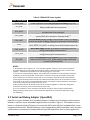
Table 3. FRDM-KL25Z Power Supplies
Power Supply Name
P5-9V_VIN
P5V_SDA
P5V_KL25Z
P3V3_VREG
P3V3_BATT
P3V3
P3V3_KL25Z
P3V3_SDA
P5V_USB
Description
Power supplied from the VIN pin of the I/O headers (J9 pin 16).
Power supplied from the OpenSDA USB connector (J7). A Schottky
diode provides back drive protection.
Power supplied from the KL25Z USB connector (J5). A Schottky diode
provides back drive protection.
Regulated 3.3V supply. Sources power to the P3V3 supply rail with an
optional back drive protection Schottky diode. 1,3
Coin cell battery supply voltage. Sources power to the P3V3 supply
rail with the option of adding a back drive protection Schottky diode.4
Main supply rail for the FRDM-KL25Z assembly. May be sourced from
P3V3_VREG, P3V3_BATT, or directly from the I/O headers (J9 pin 8)
KL25Z MCU supply. Header J4 provides a convenient means for
energy consumption measurements. 2
OpenSDA circuit supply. Header J3 provides a convenient means for
energy consumption measurements. 2
Nominal 5V supplied to the I/O headers (J9 pin 10). Sourced from
either the P5V_KL25Z or P5V_OSDA supply through a back drive
protection Schottky diode.
NOTES:
1) By default the linear regulator, U1, is a 3.3V output regulator. However, this is a common footprint
that would allow the user to modify the assembly to utilize an alternative device such as a 1.8V or 2.5V
regulator. The KL25Z microcontroller has an operating range of 1.71V to 3.6V.
2) J3 and J4 are not populated by default. The two pins of these headers are in parallel with 0 Ω resistors.
In addition, J4 is also in parallel with a 10 Ω resistor. To measure the energy consumption of the KL25Z,
either a voltmeter or an ammeter may be used. To use a voltmeter, R73 (0 Ω) must be removed before
connecting the voltmeter probes to the pins of J4. Both R73 and R81 (10 Ω) must be removed to measure
current with an ammeter. For the OpenSDA MCU, energy consumption can be measured by removing R74
(0 Ω) and connecting ammeter probes to the pins of J3.
3) D12 is bypassed by J20. By default, the pins of J20 are shorted together, to reduce the voltage drop
across D12. To use D12, cut the trace between the pins of J20.
4) If a coin cell battery is to be used add a small amount of solder to the coin cell ground pad before
adding the battery holder. Also, it is recommended to populate D7 as a protection diode when using a
coin cell battery.
5.2 Serial and Debug Adapter (OpenSDA)
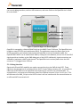
OpenSDA is an open-standard serial and debug adapter. It bridges serial and debug communications
between a USB host and an embedded target processor as shown in Figure 5. The hardware circuit is
based on a Freescale Kinetis K20 family microcontroller (MCU) with 128 KB of embedded flash and an
integrated USB controller. OpenSDA features a mass storage device (MSD) bootloader, which provides
a quick and easy mechanism for loading different OpenSDA Applications such as flash programmers,
FRDMKL25ZUM
User's Manual
Page 7 of 20