1
ArduinoStackingControllerUserManual
Rev. Jan 14, 2015
For build instructions and the most recent software and manual, please visit
http://www.ryleeisitt.ca/articles/building-a-focus-stacking-controller/
Kenwood RC-P400 Button Assignments
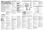
Samsung AA59-00666A Button Assignments
General Operation
From most menus, you can press the toggle backlight button to enable or disable the LCD backlight, the
exposure lock button to toggle your camera’s exposure lock (half press) mode, and the shutter release
button to take pictures. Note that when the exposure lock is enabled, a small “EL” symbol will appear in
the upper right of the display, as shown below.
When items on the screen are preceded by a digit and colon, as shown above, this indicates that you can
navigate to the associated sub-menu by pressing the corresponding digit on the remote.
You can return to a previous menu by pressing the menu button on the remote.
Main Menu
From the main menu, press the digit on the remote which corresponds to the desired task. If you have
just assembled the stacking controller or installed updated software, go to the motor configuration
(“Motor”) and camera configuration (“Camera”) menus to set up the controller as desired.
Motor Configuration
The motor configuration menu allows you to adjust the behavior of the stepper motor and provide the
stacking controller with the information necessary to calculate stack depth.
Use the up and down buttons to move between parameters. Use the enter button to toggle parameters
on and off, and digits 0-9 to modify the values of numeric parameters.
Half-step (on/off): if on (recommended), the motor is driven in half-step mode, which is more precise,
generates less vibration, uses less power, and produces less heat. The downside of half-stepping is that
it has less torque, but this should not be a concern for most applications.
Reverse (on/off): if you want the motor to move in the opposite direction when operating it from the
position menu, toggle this parameter.
St/rev: set this parameter to the number of full steps in one revolution of your stepper motor. To
determine the proper value, divide 360° by your motor's rated °/step. A 1.8 °/step motor will give a
value of 200.
µm/rev: set this parameter to the number of micrometers that your stage advances over one revolution
of the stepper motor. This value is used to calculate the stack depth readout in the position and stack
menus, but does not otherwise change the behavior of the stacking controller.
Max RPM: this parameter sets the maximum speed of the stepper motor. Experiment with different
speeds to determine what works best for you. 120 RPM should work well for many standard stepper
motors. Higher speeds are more likely to cause missed steps, stalling, and reduced torque.
Relax motor (on/off): If on (recommended), the motor is braked when not in use. This reduces heat, but
also reduces holding torque.
Accelerate (on/off): If on (recommended), the motor accelerates up to the max RPM, and then
decelerates as it approaches a target position. This can prevent skipped steps or stalling of the motor.
Setting the µm/rev parameter
The µm/rev value is the number of micrometers that your stage advances per revolution of the stepper
motor. You can determine the correct value through calculation or experiment.
By calculation:
1. Determine your gearing ratio. If you have the motor directly coupled to your stage’s adjustment
knob, your gearing ratio is 1. Otherwise, the gearing ratio is equal to the number of teeth on the
stepper motor gear/pulley divided by the number of teeth on the stage knob gear/pulley.
2. Obtain the specifications for your stage, which will hopefully tell you how many µm the
adjustment knob advances through per revolution.
3. Multiply the stage’s µm/rev by your gearing ratio. This is your µm/rev value for the stepper
motor. Input this into the configuration.
Example: the timing pulley attached to my stepper motor has 18 teeth, and the pulley on my focus
block’s fine focus knob has 30 teeth, so my gearing ratio is 0.6. According to the specifications, the focus
block advances 200 µm per revolution of the fine focus knob. So, for each revolution of the stepper
motor, my focus block will advance by 120 µm (200 µm x 0.6).
By experiment:
1. Set up your motorized stage and stacking controller as desired.
2. Using the focus stacking controller in the position menu, advance your stage through a fairly
large distance that you can accurately measure. Measure the difference between the initial and
final position using a ruler, caliper, depth micrometer, or other measuring device.
Note that 1 mm = 1000 µm.
3. Look on the focus stacking controller’s screen and note how many full steps of the stepper
motor this distance corresponds to.
4. Divide the distance in µm by the number of full steps taken. This gives you µm/step.
5. Multiply the µm/step by the number of full steps per revolution of your stepper motor. This
gives you the µm/rev value. Round it to the nearest whole number. You may wish to do this
procedure multiple times to determine an average.
Camera Configuration
The camera configuration menu allows you to adjust the behavior of the camera.
Use the up and down directional arrows to move between parameters. Use the enter button to toggle
fields on and off, and digits 0-9 to modify the values of numeric parameters.
Trigger (on/off): If off, the camera will not be triggered during stacking. This may be desired if using the
controller to operate a camera slider for video production.
Swap Relays (on/off): If the exposure lock button on your remote causes the camera to take a picture,
while the shutter release button enables exposure lock, toggle this parameter to correct this.
TV: This determines how long the shutter button is closed when photos are being taken during stacking.
If the camera is placed in bulb mode, this value will also determine the exposure time. Otherwise, it has
no effect on the photograph - it merely needs to be long enough to trigger the shutter. You should not
have to adjust this in most cases.
Position Menu
Position mode allows you to move the motorized stage back and forth and set the beginning and end
points of the stack. Press the up or right directional arrows on the remote to move forwards, and the
down or left directional arrows to move backwards.
The displayed position is the number of full steps from the initial motor position.
Press the start button to set the current position as the start point of the stack, and the stop button to
set the current position as the end point of the stack.
The seek backward and seek forward buttons will cause the stacking controller to automatically move
the motorized stage to the start or end positions, respectively.
If you have set the correct st/rev and µm/rev values in the motor configuration menu, the depth
readout will tell you the distance between the start and end positions.
To return to the main menu, press the menu button.
Stack Menu
In the stack menu, you tell the stacking controller how many positions (slices) to stop at for taking
pictures throughout the stack, the time interval (int) between subsequent shots, and the number of
shots (bracket) per position.
Use the up and down buttons on the remote to move between the parameters and modify the values
using the digits on the remote.
The total number of photos that will be taken for a stack is determined by multiplying the number of
slices by the bracket value. For normal use, leave bracket set to 1. Bracketing shots at each position can
be useful if coupled with exposure bracketing on a camera to produce HDR stacks.
If you use flashes or strobes for illumination, consult the user manual for your light to determine the
recommended time interval between shots to prevent overheating. If using continuous lighting, you can
safely reduce the interval to the minimum necessary for reliable camera operation.
The number of slices should be set high enough to ensure that the resulting stack does not exhibit focus
banding (alternating bands of in-focus and out-of-focus areas). Setting the number of slices too high,
however, will contribute to increased wear on your camera’s shutter mechanism, as well as require
more storage space and time to process the stack.
Before you start the stacking process, you can enable the exposure lock mode (indicated by an EL
symbol in the upper right of the display) by pressing the exposure lock button on the remote. This will
keep the camera in a ready-to-shoot state during the entire stack which may decrease shutter lag and
prevent the camera from entering a power saving mode. If exposure lock is not enabled, the controller
will automatically enable and disable the exposure lock mode for each shot, which may be desired if you
wish to see the results of each shot on the camera’s LCD or video output.
Once the parameters are set to your liking, press the start button to begin the stack.
During a stack, the motorized stage will automatically move between slices, and shots will automatically
be taken at the desired time interval. The current progress will be updated on the LCD after every shot
taken. While the stacking controller is operating and photos are being taken, avoid touching the camera,
subject, table, or apparatus to prevent movement and vibrations.
You can cancel a stack at any time by pressing the stop button.
Debug Menu
The debug menu is intended for testing and trouble-shooting. The free mem value indicates the amount
of free RAM (in bytes). Care has been taken to ensure that the software does not use too much RAM. If
you are experiencing odd behavior from your stacking controller, check this value during operation to
ensure that your microcontroller is not running out of available memory. Low memory will cause
extremely unpredictable behavior.
The test motor feature will automatically test your stepper motor using multiple combinations of
settings and will measure the actual RPM against several target RPM settings. If you make changes to
the code in the stepper motor library, use this feature to test whether the code is functioning correctly.
If the motor and software is behaving correctly, actual RPM values will be close to the set RPM, and the
position of the motor’s drive shaft will return to the same position it started in prior to beginning the
test sequence.
The microcontroller’s EEPROM is used to save customized configuration values even when the device is
disconnected from power. The clear EEPROM feature can be used to restore all of the configuration
settings to their defaults. After use, reset your controller by pressing the reset button on the
microcontroller board or by disconnecting and then reconnecting the power supply. This will load the
default values into the EEPROM.
Problems?
Although I run the hardware and software through a testing procedure prior to issuing software
updates, bugs do slip through. If you have problems, please visit http://www.ryleeisitt.ca and use the
contact form to get in touch with me. I can usually issue patched software fairly quickly once a problem
has been identified.
Happy stacking!