1
User Manual
for the
CD--ROM JUKEBOX Series
CDR 100
WARNING
TO REDUCE FIRE OR SHOCK HAZARD, DO NOT EXPOSE THIS APPLIANCE TO
RAIN OR MOISTURE.
TO REDUCE THE RISC OF ELECTRICAL SHOCK, DO NOT REMOVE THE
PLASTIC COVER INSIDE THE CHANGER.
NO USER--SERVICABLE PARTS INSIDE.
REFER SERVICING TO QUALIFIED SERVICE PERSONNEL!
NOTE:
Replace fuses only with same type and values!
In case hardware problems are encountered during installation or operation, it is recommended that you contact your supplier or the vendor from which you purchased the equipment.
CLASS 1
LASER PRODUCT
according to IEC 825
Important notice
Disassembling parts and changing any adjustments, apart from those specified within this
manual, may result in exposure to hazardous laser radiation.
CAUTION ! Use of controls or adjustment or performance of procedures other than those
specified herein may result in hazardous radiation exposure.
The information and illustration contained in this manual are up to date at the time of publication.
Subject to technical modification without obligation to modify equipment already delivered!
This document is subject to change by NSM without notice.
Version 12/98 - 1
Copyright:
NSM Jukebox GmbH, D 55411 Bingen am Rhein, Germany
No reprint un full or part unless approved!
Part no. of this document: 141 464
II
User manual
NSM Jukebox Series CDR 100
Hot--Line--Service
Necessary service is supported by your distributor.
Hot--Line:
International: +49 6721 964 222
Deutschland: 06721 964 222
USA: 1 800 238 4676
EG -- KONFORMITÄTSERKLÄRUNG
EC -- DECLARATION OF CONFORMITY
CE -- DECLARATION DE CONFORMITE
mit der Richtlinie 89 / 336 / EWG.
per 89 / 336 / EEC.
avec 89 / 336 / CEE.
Hiermit wird bestätigt, daß das Produkt
This is to confirm that the product
Nous déclarons que le produit
CD--ROM Jukebox
Serie CDR 100
CD--ROM Jukebox
Series CDR 100
Jukebox CD--ROM
Série CDR 100
mit den folgenden Normen bzw. normativen Dokumenten übereinstimmt:
is in conformity with the following standards or
other normative documents:
est conforme aux normes ou autres documents
normatifs suivants:
EN 50081-- 1, EN 550 22,
EN 61000-- 3-- 2, EN 61000-- 3-- 3,
EN 50082-- 1,
IEC 801--2, IEC 801--3, IEC 801--4,
EN 60950.
EN 50081-- 1, EN 550 22,
EN 61000-- 3-- 2, EN 61000-- 3-- 3,
EN 50082-- 1,
IEC 801--2, IEC 801--3, IEC 801--4,
EN 60950.
EN 50081-- 1, EN 55 022,
EN 61000-- 3-- 2, EN 61000-- 3-- 3,
EN 50082-- 1,
IEC 801--2, IEC 801--3, IEC 801--4,
EN 60950.
Das Qualitätssicherungssystem der NSM garantiert die Konformität.
NSM quality assurance system assures compliance.
Le système d’assurance de la qualité de NSM garantit la conformité.
NSM Jukebox GmbH
NSM Jukebox GmbH
NSM Jukebox GmbH
Im Tiergarten 20--30
D--55411 Bingen am Rhein
Im Tiergarten 20--30
D--55411 Bingen am Rhein, Germany
Im Tiergarten 20--30
D--55411 Bingen am Rhein, Allemagne
02--26--96
26.02.96
26.02.96
Armin Frank
User manual
NSM Jukebox Series CDR 100
Armin Frank
Armin Frank
III
NOTE: This equipment has been tested and found to comply with the limits for a Class B
digital device, pursuant to Part 15 of the FCC Rules. These limits are designed to provide
reasonable protection against harmful interference in a residential installation. This equipment generates, uses and can radiate radio frequency energy and, if not installed and used
in accordance with the instructions, may cause harmful interference to radio communications. However, there is no guarantee that interference will not occur in a particular installation. If this equipment does cause harmful interference to radio or television reception, which
can be determined by turning the equipment off and on, the user is encouraged to try to correct the interference by one or more of the following measures:
-- Reorient or relocate the receiving antenna.
-- Increase the separation between the equipment and receiver.
-- Connect the equipment into an outlet on a circuit different from that to which the receiver
is connected.
-- Consult the dealer or an experienced radio/TV technician for help.
Important: This product was FCC verified under test conditions that include use of shielded
cables and connectors between system components. It is important that you use shielded
cables and connectors to reduce the possibility of causing interference to radios, TV sets
and other electronic devices.
If you have any problems contact your dealer.
Any change or modifications to the equipment by the user not expressly approved by the
grantee or manufacturer could void the user’s authority to operate such equipment.
IV
User manual
NSM Jukebox Series CDR 100
Table of Contents . . . . . . . . . . . . . . . . . . . . . . . . . . . . . . . . . . . . . . . . . . . . . . . . . . . . . . . . . . . . V
List of figures . . . . . . . . . . . . . . . . . . . . . . . . . . . . . . . . . . . . . . . . . . . . . . . . . . . . . . . . . . . . . . . . . . . . . . . . . . . . . . . . VI
List of tables . . . . . . . . . . . . . . . . . . . . . . . . . . . . . . . . . . . . . . . . . . . . . . . . . . . . . . . . . . . . . . . . . . . . . . . . . . . . . . . . . VI
1. The NSM Jukebox series CDR 100 . . . . . . . . . . . . . . . . . . . . . . . . . . . . . . . . . . . . . . . . 1-- 1
2. Unpacking the jukebox . . . . . . . . . . . . . . . . . . . . . . . . . . . . . . . . . . . . . . . . . . . . . . . . . . . 2-- 1
2.1
2.2
Packing List . . . . . . . . . . . . . . . . . . . . . . . . . . . . . . . . . . . . . . . . . . . . . . . . . . . . . . . . . . . . . . . . . . . . . . . . . . . 2--1
Unpacking . . . . . . . . . . . . . . . . . . . . . . . . . . . . . . . . . . . . . . . . . . . . . . . . . . . . . . . . . . . . . . . . . . . . . . . . . . . . 2--1
3. Installation . . . . . . . . . . . . . . . . . . . . . . . . . . . . . . . . . . . . . . . . . . . . . . . . . . . . . . . . . . . . . . 3-- 1
3.1
3.2
3.3
3.4
3.5
3.6
3.7
3.8
Preparing the Installation Site . . . . . . . . . . . . . . . . . . . . . . . . . . . . . . . . . . . . . . . . . . . . . . . . . . . . . . . . . . . 3--1
Setting the ID. Number . . . . . . . . . . . . . . . . . . . . . . . . . . . . . . . . . . . . . . . . . . . . . . . . . . . . . . . . . . . . . . . . . 3--1
Setting the DIP SWITCH . . . . . . . . . . . . . . . . . . . . . . . . . . . . . . . . . . . . . . . . . . . . . . . . . . . . . . . . . . . . . . . 3--3
3.3.1 DIP switch setting for Jukeboxes with Yamaha CDR100 or Toshiba XM--3501B drive . . . . . 3--3
3.3.2 DIP switch setting for Jukeboxes with TEAC CD--516S drive . . . . . . . . . . . . . . . . . . . . . . . . . . 3--4
3.3.3 DIP switch setting for Jukeboxes with Plextor PX--R412 drive . . . . . . . . . . . . . . . . . . . . . . . . . 3--5
3.3.4 DIP switch setting for Jukeboxes with Toshiba DVD drive SD--W1101 . . . . . . . . . . . . . . . . . . 3--6
Installation of the Terminating Resistor . . . . . . . . . . . . . . . . . . . . . . . . . . . . . . . . . . . . . . . . . . . . . . . . . . . 3--7
Connecting the Jukebox to the host system . . . . . . . . . . . . . . . . . . . . . . . . . . . . . . . . . . . . . . . . . . . . . . . 3--8
3.5.1 Length of the SCSI cable for Jukeboxes with TEAC CD--516S drive . . . . . . . . . . . . . . . . . . . . 3--8
Concatenating of more Jukeboxes . . . . . . . . . . . . . . . . . . . . . . . . . . . . . . . . . . . . . . . . . . . . . . . . . . . . . . . 3--9
Connecting the Jukebox to an Audio Amplifier . . . . . . . . . . . . . . . . . . . . . . . . . . . . . . . . . . . . . . . . . . . . 3--10
Equipment of the CD--ROM Storage Magazines . . . . . . . . . . . . . . . . . . . . . . . . . . . . . . . . . . . . . . . . . . 3--11
4. Operating Instruction . . . . . . . . . . . . . . . . . . . . . . . . . . . . . . . . . . . . . . . . . . . . . . . . . . . . 4-- 1
4.1
4.2
4.3
4.4
4.5
Changing the mains voltage . . . . . . . . . . . . . . . . . . . . . . . . . . . . . . . . . . . . . . . . . . . . . . . . . . . . . . . . . . . . .
Switching ON the Jukebox . . . . . . . . . . . . . . . . . . . . . . . . . . . . . . . . . . . . . . . . . . . . . . . . . . . . . . . . . . . . . .
LED operation display . . . . . . . . . . . . . . . . . . . . . . . . . . . . . . . . . . . . . . . . . . . . . . . . . . . . . . . . . . . . . . . . . .
Care of discs . . . . . . . . . . . . . . . . . . . . . . . . . . . . . . . . . . . . . . . . . . . . . . . . . . . . . . . . . . . . . . . . . . . . . . . . . .
Control Software . . . . . . . . . . . . . . . . . . . . . . . . . . . . . . . . . . . . . . . . . . . . . . . . . . . . . . . . . . . . . . . . . . . . . . .
4.5.1 ACROM . . . . . . . . . . . . . . . . . . . . . . . . . . . . . . . . . . . . . . . . . . . . . . . . . . . . . . . . . . . . . . . . . . . . . . .
4.5.2 ACROMTSR . . . . . . . . . . . . . . . . . . . . . . . . . . . . . . . . . . . . . . . . . . . . . . . . . . . . . . . . . . . . . . . . . . .
4.5.3 ACSCAN . . . . . . . . . . . . . . . . . . . . . . . . . . . . . . . . . . . . . . . . . . . . . . . . . . . . . . . . . . . . . . . . . . . . . .
4--1
4--1
4--2
4--2
4--3
4--3
4--5
4--6
5. Serial Interface . . . . . . . . . . . . . . . . . . . . . . . . . . . . . . . . . . . . . . . . . . . . . . . . . . . . . . . . . . 5-- 1
5.1
5.2
5.3
Adress Byte . . . . . . . . . . . . . . . . . . . . . . . . . . . . . . . . . . . . . . . . . . . . . . . . . . . . . . . . . . . . . . . . . . . . . . . . . . .
Command Structure . . . . . . . . . . . . . . . . . . . . . . . . . . . . . . . . . . . . . . . . . . . . . . . . . . . . . . . . . . . . . . . . . . . .
Command Description . . . . . . . . . . . . . . . . . . . . . . . . . . . . . . . . . . . . . . . . . . . . . . . . . . . . . . . . . . . . . . . . . .
5.3.1 Request Jukebox ID.number . . . . . . . . . . . . . . . . . . . . . . . . . . . . . . . . . . . . . . . . . . . . . . . . . . . . .
5.3.2 Load Disc from magazine . . . . . . . . . . . . . . . . . . . . . . . . . . . . . . . . . . . . . . . . . . . . . . . . . . . . . . . .
5.3.3 Return Disc to magazine . . . . . . . . . . . . . . . . . . . . . . . . . . . . . . . . . . . . . . . . . . . . . . . . . . . . . . . . .
5.3.4 Request Status . . . . . . . . . . . . . . . . . . . . . . . . . . . . . . . . . . . . . . . . . . . . . . . . . . . . . . . . . . . . . . . . .
5--1
5--3
5--5
5--5
5--6
5--7
5--8
6. Technical Data . . . . . . . . . . . . . . . . . . . . . . . . . . . . . . . . . . . . . . . . . . . . . . . . . . . . . . . . . . . 6-- 1
6.1
6.2
6.3
6.4
Factory settings . . . . . . . . . . . . . . . . . . . . . . . . . . . . . . . . . . . . . . . . . . . . . . . . . . . . . . . . . . . . . . . . . . . . . . .
Environmental operating limits . . . . . . . . . . . . . . . . . . . . . . . . . . . . . . . . . . . . . . . . . . . . . . . . . . . . . . . . . . .
Dimensions . . . . . . . . . . . . . . . . . . . . . . . . . . . . . . . . . . . . . . . . . . . . . . . . . . . . . . . . . . . . . . . . . . . . . . . . . . .
Performance of the CD--ROM drives . . . . . . . . . . . . . . . . . . . . . . . . . . . . . . . . . . . . . . . . . . . . . . . . . . . . .
6.4.1 CD--ROM drive ”Toshiba XM3501 B” . . . . . . . . . . . . . . . . . . . . . . . . . . . . . . . . . . . . . . . . . . . . . . .
6.4.2 CD--ROM drive ”Yamaha CDR 100 Recordable” . . . . . . . . . . . . . . . . . . . . . . . . . . . . . . . . . . . . .
6.4.3 CD--ROM drive ”TEAC CD--516S” . . . . . . . . . . . . . . . . . . . . . . . . . . . . . . . . . . . . . . . . . . . . . . . . .
6.4.4 CD--ROM drive ”Plextor PX--R412” . . . . . . . . . . . . . . . . . . . . . . . . . . . . . . . . . . . . . . . . . . . . . . . .
6.4.5 CD--ROM drive ”Toshiba SD--W1101 DVD” . . . . . . . . . . . . . . . . . . . . . . . . . . . . . . . . . . . . . . . . .
6--1
6--1
6--2
6--3
6--3
6--4
6--5
6--6
6--7
Appendix:
Control software and test software
User manual
NSM Jukebox Series CDR 100
V
List of figures
figure 1: Jukebox, general view . . . . . . . . . . . . . . . . . . . . . . . . . . . . . . . . . . . . . . . . . . . . . . . . . . . . . . . . . . . . . . . . 1--1
figure 2: Opening of the Jukebox . . . . . . . . . . . . . . . . . . . . . . . . . . . . . . . . . . . . . . . . . . . . . . . . . . . . . . . . . . . . . . 2--1
figure 3: Removing fo the transportation figures . . . . . . . . . . . . . . . . . . . . . . . . . . . . . . . . . . . . . . . . . . . . . . . . . . 2--2
figure 4: NSM Interface board inside the Jukebox . . . . . . . . . . . . . . . . . . . . . . . . . . . . . . . . . . . . . . . . . . . . . . . . 3--2
figure 5: Setting the DIP switch for Jukeboxes with Yamaha CDR100 or Toshiba XM--3501B drive . . . . . . 3--3
figure 6: Setting the DIP switch for Jukeboxes with TEAC CD--516S drive . . . . . . . . . . . . . . . . . . . . . . . . . . . 3--4
figure 7: Setting the DIP switch for Jukeboxes with Plextor PX--R412 drive . . . . . . . . . . . . . . . . . . . . . . . . . . 3--5
figure 8: Setting the DIP switch for Jukeboxes with Toshiba SD--W1101 DVD drive . . . . . . . . . . . . . . . . . . . 3--6
figure 9: Rear view of the Jukebox, placement of the interface connectors . . . . . . . . . . . . . . . . . . . . . . . . . . . 3--7
figure 10: Connecting one or more Jukebox units . . . . . . . . . . . . . . . . . . . . . . . . . . . . . . . . . . . . . . . . . . . . . . . . 3--8
figure 11: Connecting the jukebox to an audio amplifier . . . . . . . . . . . . . . . . . . . . . . . . . . . . . . . . . . . . . . . . . . 3--10
figure 12: CDR 100, Disc handling and placing directives . . . . . . . . . . . . . . . . . . . . . . . . . . . . . . . . . . . . . . . . 3--11
figure 13: Changing the Mains voltage . . . . . . . . . . . . . . . . . . . . . . . . . . . . . . . . . . . . . . . . . . . . . . . . . . . . . . . . . . 4--1
figure 14: Rear view of the Jukebox, power connection . . . . . . . . . . . . . . . . . . . . . . . . . . . . . . . . . . . . . . . . . . . 4--1
figure 15: Front view of the Jukebox, LED display . . . . . . . . . . . . . . . . . . . . . . . . . . . . . . . . . . . . . . . . . . . . . . . . 4--2
figure 16: Timing of one communication cycle . . . . . . . . . . . . . . . . . . . . . . . . . . . . . . . . . . . . . . . . . . . . . . . . . . . 5--1
figure 17: Structure of the address byte . . . . . . . . . . . . . . . . . . . . . . . . . . . . . . . . . . . . . . . . . . . . . . . . . . . . . . . . . 5--1
List of tables
table 1: Colour modes of the status LED . . . . . . . . . . . . . . . . . . . . . . . . . . . . . . . . . . . . . . . . . . . . . . . . . . . . . . . .
table 2: Command block structure . . . . . . . . . . . . . . . . . . . . . . . . . . . . . . . . . . . . . . . . . . . . . . . . . . . . . . . . . . . . .
table 3: Acknowledge block structure . . . . . . . . . . . . . . . . . . . . . . . . . . . . . . . . . . . . . . . . . . . . . . . . . . . . . . . . . . .
table 4: List of available commands . . . . . . . . . . . . . . . . . . . . . . . . . . . . . . . . . . . . . . . . . . . . . . . . . . . . . . . . . . . .
table 5: List of possible return codes . . . . . . . . . . . . . . . . . . . . . . . . . . . . . . . . . . . . . . . . . . . . . . . . . . . . . . . . . . .
table 6: List of possible status codes . . . . . . . . . . . . . . . . . . . . . . . . . . . . . . . . . . . . . . . . . . . . . . . . . . . . . . . . . . .
VI
4--2
5--3
5--3
5--4
5--4
5--8
User manual
NSM Jukebox Series CDR 100
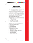
1. The NSM Jukebox series CDR 100
The jukebox CDR 100 is a CD--ROM changer. It is based on the wellknown NSM CD-ROM changer for maximum 100 CD’s. The jukebox includes a single ended Small Computer Systems Interface (SCSI -- 2) for data exchange with a SCSI host and a RS232 interface for control purposes.
Up to 7 SCSI devices (as CDR 100 XA, WORM, HD--drives, ...) may be connected to a
single SCSI host adapter by cascading the SCSI interface and the RS232 interface.
The volume of the jukebox is max. 100 CD’s.
Digital Audio (Red Book, IEC 908, Compact Disc Digital Audio System) is routed through
the embedded audio interface to two stereo line out connectors at the rear side of the
jukebox.
The stereo line out signal may be connected to any stereo amplifier.
figure 1: The Jukebox CDR 100, general view
User manual
NSM Jukebox Series CDR 100
1--1
1--2
User manual
NSM Jukebox Series CDR 100
2. Unpacking
2.1 Packing List
The package of the jukebox should contain the following items:
1.)
2.)
3.)
4.)
5.)
6.)
7.)
8.)
9.)
10.)
11.)
1 CDR 100 jukebox
1 CD--ROM user manual
1 Quick installation guide
1 single ended SCSI--2 bus terminator
1 RS232 control cord NSM
1 power cord
2 CD magazines with room for 50 4,72” CDs each
100 trays for 4,72” CDs
2 keys for the front door lock
3 spare fuses
2 spare lamps
2.1.1 List of Transportation Fixtures
1.)
1 paper transportation fixture/ CARD BOARD for the CD storage
magazines
2.) 8 metal clamps mounted to the CD storage magazines
3.) 1 fixture profile,(slitted plastic pipe), which is fixing the CD jukebox
{4.) 1 transportation security bracket within the DVD--drive}
2.2 Unpacking
Gently lift out the jukebox of the package and remove the packing pieces.
Make sure that the package contains all of the items listed in Ch. 2.1. If any of the items
are missing, please contact your supplier immediately and request these parts.
Please open the front door of the jukebox by
inserting one of the supported keys into the
lock and turning it to the right side. Gently
push the lock with the key backwards into
the appliance.
Now the front door will smoothly fold forward.
When the door is open, remove the paper
transportation fixture, located between the
two CD storage magazines.
figure 2: Opening of the CDR 100
User manual
NSM Jukebox Series CDR 100
2--1
For simplified description only the right CD
magazin is shown in figure 3.
Fold the two CD storage magazines to the
outside by moving the two corresponding
black knobs to the out side of the appliance
and folding the left magazine to the left and
the right magazine to the right.
Remove the red plastic splint (1.) mounted to
the center metal bar by gently pulling it towards you.
Keep the storage magazines in their position.
Please remove the four metal clamps, mounted to each of the CD storage magazines, by
taking the thick end of each metal clamp and
slightly pulling it away from the CD storage
magazine.
Please make sure that all transportation fixtures are removed from the inside of the
jukebox (see Ch. 2.1.1).
1.
Please fold back the two storage magazines
and close the front door.
2.
Attention: If you have got a CDR 100 jukebox with DVD-- drive remove the transportation security bracket from the drive (2.).
figure 3: Removing of the transportation figures
NOTE: If the CDR 100 package shows evidence of rough handling or damage,
and if the jukebox therefore does not function properly on initial start--up, please
immediately return the unit and the damaged package to your supplier and request a replacement.
2--2
User manual
NSM Jukebox Series CDR 100
3. Installation
The necessary items to install your CDR 100 jukebox are:
a host system,
a 9 pin RS232 male -- female interface cord
a SCSI host adapter,
a SCSI interface cord,
a SCSI single ended bus terminator,
a small screw driver.
Installation Note
To prevent any damages to your CDR 100 or to any connected device please
regard:
Before you connect the CDR 100 to any device, or before you make any
changes to the connection between the CDR 100 and a device, please make
sure to switch off the power supply of the CDR 100 and any connected device
(i.e. host system, audio amplifier). Otherwise damages may be caused to the
CDR 100 and the connected device(s).
3.1 Preparing the Installation Site
If you do not yet have a SCSI host adapter installed into your host system, please install
the SCSI host adapter board and the corresponding SCSI device driver supported by the
vendor of the SCSI host adapter first.
For detailed instructions on the installation of the SCSI host adapter and the SCSI device
driver, please refer to the user manual supported with your host system and the user manual supported with your SCSI host adapter board.
3.2 Setting the ID.number
The ID. switches of the CDR 100 allow to choose between 7 SCSI ID.s (0...6) and 16
RS232 ID.s (0...F).
If the CDR 100 is the only SCSI device connected to your system, it is not necessary to
change the factory settings of the SCSI port and the serial port. In this case, reading this
chapter is not necessary and you may continue reading chapter 3.3.
If the CDR 100 is to be added to previously installed SCSI devices such as CDR 100’s,
WORM’s, MOD’s or others, please select a SCSI ID.number (SCSI adress) and a serial
ID.number (serial adress) for the CDR 100 that is not used by any of the previously installed devices. Valid ID.numbers are 0 .. 6.
I.e.: If your host system already has two SCSI hard disc drives with ID 0 and ID 1, select
ID 2 for the CDR 100.
User manual
NSM Jukebox Series CDR 100
3--1
Changing the ID. number of the CDR 100
To change the ID.number of the SCSI port and/or the serial port you first have to open the
front door of the CDR 100 by inserting one of the supported keys and turning it to the right
side. Gently push the lock backwards into the appliance. Now the front door will smoothly
fold forward (see figure 2). When the door is totally opened fold out the right CD storage
magazine to the outside by moving the corresponding knob to the inner side. Remove the
right--hand storage magazine by holding it with your right hand and moving the knob to the
outside. Put the storage magazine to a save place.
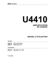
Locate the Interface board at the right side of the inner back plane of the CDR 100 unit. To
select a new ID.number you have to use a small screw driver. Set the desired ID.number
by turning the arrow of the switch to the position with the number that represents the
ID.number.
Refer to the following figure.
ST1
INTERFACE
BOARD
RS232 ID.s
0...F
RS232 ID.
6 8A
4
C
2 E
0
S1
SCSI ID.s
0...6
DIP Switch
ST2
SCSI ID.
456
3
7
2
8
109
3
2
1
JP1
ST5
ST6
shown positions
= factory default
S2
87654321
ON
ST4
ST3
S3
figure 4: Interface board inside the CDR 100
NOTE: We suggest that you choose the same selection for SCSI ID. as well as the serial
ID.number.
In case of concatenating more than one CDR 100 by daisy chain, it is important to take
care that all units (0...6) are set to the same baud rate. If you use a second SCSI host
adapter we suggest to use the following setting:
ID. 0...6 for SCSI and RS232 for the first seven jukeboxes and
ID. 0...6 for SCSI resp. ID. 7...D for RS232 for the second seven unit’s of
CDR 100.
3--2
User manual
NSM Jukebox Series CDR 100
3.3 Setting the DIP switch
Use DIP switch S3 to select baudrate for the serial interface and data parity for the SCSI
bus.
To make any changes to DIP switch S3 use a small screw driver to move the switches into
the appropriate position (ON or OFF).
Please note, that the setting off the DIP switch S3 depends on the type of installed drive.
The following information will help you to choose the right setting
3.3.1 DIP switch setting for jukeboxes with Yamaha CDR100 or Toshiba XM3501B
drives
3
2
1
JP1
DIP SWITCH
Jumper JP1 setting:
3
ST5
ST6
2
1
87654321
JP1
ST3
ON S3
Position
Meaning
1 -- 2 Termination power off
2 -- 3 Termination power on
= active
factory default: all switches = OFF
figure 5: Setting the DIP switch for jukeboxes with Yamaha CDR100 or Toshiba XM3501B
Switch
1
2
3
4
5
6
7
8
Function
Data parity
Not used
*
*
Baudrate setting
Baudrate setting
Not used
*
ON
disabled
OFF
enabled
refer to Note 1
* = Factory use only; must always be OFF
Note 1: Baudrate setting:
Baud
1200
9600
19200
DIP 5
OFF
OFF
ON
User manual
NSM Jukebox Series CDR 100
DIP 6
ON
OFF
OFF
3--3
3.3.2 DIP switch setting for jukeboxes with TEAC CD-- 516S drive
3
2
1
JP1
DIP SWITCH
ST5
ST6
Jumper JP1 (TermPWR) must be
removed for operation with TEAC
16x--drive CD--516S.
87654321
ST3
ON S3
figure 6: Setting the DIP switch for jukeboxes with TEAC--CD 516S drive
Switch
1
2
3
4
5
6
7
8
Function
ON
OFF
Data parity
disabled
enabled
For TEAC drive CD--516S always set to ON
Block size
512 Byte
2048 Byte
*
Baudrate setting
refer to Note 1
Baudrate setting
Not used
*
* = Factory use only; must always be OFF
Note 1: Baudrate setting:
Baud
1200
9600
19200
3--4
DIP 5
OFF
OFF
ON
DIP 6
ON
OFF
OFF
User manual
NSM Jukebox Series CDR 100
3.3.3 DIP switch setting for jukeboxes with Plextor PX--R412 drive
3
2
1
JP1
DIP SWITCH
ST5
ST6
Jumper JP1 must be removed for
operation with Plextor drive
PX--412R.
87654321
ST3
ON S3
figure 7: Setting the DIP switch for jukeboxes with Plextor PX--R412 drive
DIP
1
2
3
4
5
6
7
8
Function
ON
OFF
Data parity
disabled
enabled
For Plextor PX--R412 always set to
OFF
Not used
Block size
512 Byte
2048 Byte
Baudrate setting
refer to Note 1
Baudrate setting
Not used
Factory use only; must always be OFF
Note 1: Baudrate setting:
Baud
1200
9600
19200
DIP 5
OFF
OFF
ON
User manual
NSM Jukebox Series CDR 100
DIP 6
ON
OFF
OFF
3--5
3.3.4 DIP switch setting for jukeboxes with Toshiba SD--W1101 DVD drive
3
2
1
JP1
DIP SWITCH
ST5
ST6
Jumper JP1 must be removed for
operation with DVD drive SD--W1101.
87654321
ST3
ON S3
figure 8: Setting the DIP switch for jukeboxes with Toshiba SD--W1101 DVD drive
DIP
1
2
3
4
5
6
7
8
Function
Not used
Verify
One lun/two lun
Block size
Baudrate setting
Baudrate setting
Not used
ON
enabled
two lun
512 Byte
OFF
disabled
one lun
2048 Byte
refer to Note 1
Factory use only; must always be OFF
Note 1: Baudrate setting:
Baud
1200
9600
19200
DIP 5
OFF
OFF
ON
DIP 6
ON
OFF
OFF
Note: This DVD drive is tested and found to comply with the limits for electro-- magnetically distortions defined by CE certificates, if it is connected to Adaptec 2949 /
3940 SCSI controller cards. With other controller cards the limits may be exceeded.
Terminating the necessary settings
If you have made all changes, return the CD storage magazine by pushing it into the
corresponding hinges and close the front door by latching it into its closed position.
3--6
User manual
NSM Jukebox Series CDR 100
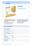
3.4 Installation of the Terminating Resistor
The last device on the SCSI Bus has to be terminated with a SCSI bus terminator. Two
kinds of bus termination are possible: Active termination is equipped with an internal
power supply. Passive bus termination needs an external power supply. Such a passive
bus termination resistor network is supplied with the CDR 100 jukebox(see Chapter 2.1).
RS232
AUDIO
To mount the terminator to the last device in a SCSI daisy chain gently push the terminator
into one of the two 50 pin Delta Ribbon female connectors, located on the lower left corner
of the CDR 100 back plane and fasten the two clamps to the connector by folding them
towards the connector.
L
R
Cinch connectors
IN
OUT
SCSI
9 pin D--SUB connectors
50 pin Delta Ribbon
female connectors
figure 9: Rear view of the CDR 100, placement of the interface connectors
User manual
NSM Jukebox Series CDR 100
3--7
3.5 Connecting the jukebox to the host system
Before you connect the CDR 100 to your host system, please make sure to switch off the
power supply of the CDR 100 and the host. Do you have the correct SCSI and RS232
cord? Refer to the user manual of your host system.
NOTE: Using the wrong SCSI interface cord may damage your SCSI host adaptor
permanently!
Take the supplied RS232 control cord and gently push the 9 pin D--Sub male connector
into the 9 pin D--Sub female connector marked as RS232 IN (see figure 9). Gently push
the 9 pin D--Sub female connector on the other end of the RS232 cord into the 9 pin D-Sub RS 232 interface male connector of your host system.
Gently push the 50 pin Delta Ribbon male connector on the one end of your SCSI interface cord into the remaining 50 pin Delta Ribbon female connector located on the lower
left corner of CDR 100 back plane (see figure 9) and fasten the two clamps to the connector, by folding them towards the connector. Gently push the male connector on the other
end of the SCSI interface cord into the female connector of the SCSI host adapter installed in your host system.
3.5.1 Length of the SCSI cord for CDR 100 jukebox with TEAC drive CD-- 516S
AUDIO
R
IN
OUT
SCSI
L
RS232
Please note the following information if you operate a CDR 100 jukebox with a TEAC drive
CD--516S:
-- Disable the Plug & Play support in the Host--Adaptor--BIOS!
-- The TEAC drive supports ”Ultra--Wide--SCSI--Standard” (UW--SCSI).
To guarantee a troublfree operation the length of the SCSI cord should not exceed
1,5m (internal length of the SCSI--bus = 0,8m).
-- For operation with SCSI cord > 1,5m the UW--SCSI support has to be disabled in
the Host--Adaptor--BIOS.
figure 10: Connecting one or more CDR 100 units
3--8
User manual
NSM Jukebox Series CDR 100
3.6 Concatenating of more CDR 100 jukeboxes
For concatenating two or more CDR 100 you need to have an additional SCSI interface
cord and an additional RS232 control cord for each additional CDR 100 unit you wish to
concatenate.
Step 1: Set the RS232 ID. number as described in Ch. 3.2. Choose a different ID for each
CDR 100 unit you wish to connect.
Step 2: Set the SCSI ID. number as described in Ch. 3.2. For each CDR 100 unit choose
the same SCSI ID. number as you have selected for the RS232 ID. number.
Step 3: Connect the first CDR 100 unit of the daisy chain to the host system as described
in chapter 3.4. Do not mount the terminating resistor network.
Step 4: Take the additional RS232 interface cord and gently push the 9 pin D--Sub female
connector located at the one end of the RS232 cord into the 9 pin D--Sub male
connector marked as RS232 OUT, located at the back plane of the first CDR 100
unit of the daisy chain (see figure 10).
Step 5: Gently push the 9 pin D--Sub male connector on the other end of the RS232 cord
into the 9 pin D--Sub connector marked as RS232 IN, located at the back plane of
the next CDR 100 unit (see figure 10) of the daisy chain.
Step 6: Take the additional SCSI interface cord and gently push the 50 pin Delta Ribbon
male connector located at the one end of the SCSI interface cord into the remaining 50 pin Delta Ribbon male connector located at the back plane of the first
CDR 100 unit (see figure 10) of the daisy chain.
Step 7: Gently push the 50 pin Delta Ribbon male connector on the other end of the SCSI
interface cord into one of the 50 pin Delta Ribbon male connector located at the
back plane of the second CDR 100 unit of the daisy chain (see figure 10).
Step 8: If you are going to concatenate more than 2 CDR 100 units, proceed with Step 4
to Step 7 until you have connected the last CDR 100 unit to the chain.
Step 9: Take the terminating resistor network and gently push it into the remaining 50 pin
Delta Ribbon female connector of the last CDR 100 unit of the daisy chain.
NOTE: --The total length of the RS232 bus shall not exceed 15 meters.
--The total length of the single ended SCSI bus should not exceed 6 meters
(regard that the internally used cable length of the jukebox is 0,8m!).
-- To a standard RS232 output 3 CDR 100 jukeboxes can be connected.
If you want to connect more than 3 jukeboxes you must take care that
the RS232--driver have the necessary output power.
User manual
NSM Jukebox Series CDR 100
3--9
3.7 Connecting the jukebox to an Audio Amplifier
Before you connect the CDR 100 to any audio amplifier, please make sure to switch off the
power supply of either the CDR 100 and the audio amplifier.
You will only need a standard audio cord of the required length with two male cinch connectors at both ends. Gently push the male cinch connectors into the female cinch connectors located at the back plane of the CDR 100 unit (see figure 11) one after the other
and connect the other end of the audio cord to your amplifier referring to the user manual
of it.
L
R
Audio amplifier of the jukebox.
Cinch--connector
figure 11: Connecting the jukebox to an audio amplifier
3--10
User manual
NSM Jukebox Series CDR 100
3.8 Equipment of the CD Storage Magazines
To equip the CD storage magazines open the front door of the CDR 100 by inserting one
of the supported keys into the lock and turning it to the right side. Gently push the lock with
the inserted key backwards into the unit. Now the front door will smoothly fold forward.
When the door is totally opened fold the two CD storage magazines to the outside by
pressing the corresponding black knobs to the inner side and folding the left magazine to
the left and the right magazine to the right (see figure 3).
Remove the right--hand storage magazine by holding it with your right hand and pressing
the right--hand, black knob to the right side (see figure 3).
Remove the left--hand storage magazine by holding it with your left hand and pressing the
left--hand, black knob to the left side (see figure 3).
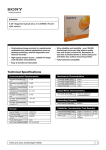
Remove a number of CD trays corresponding to the number of CDs you wish to insert into
the magazine. Into the recess of each tray, place a CD face up (label up), and thereupon
slide the tray into the first available slot of the magazine.
NOTE:
CDs have to be placed face up respectively label up into the CD trays.
Otherwise the CDR 100 may cause an error when accessing the wrong
inserted CD.
Always place
the CDs
face up
!
Photo CD for example
CD tray
figure 12: CDR 100, disc handling and placing directives
Return the two CD storage magazines by pushing them into the corresponding hinges and
close the front door by latching it into its closed position.
User manual
NSM Jukebox Series CDR 100
3--11
4. Operating instruction
4.1 Changing the Mains voltage:
To change the mains voltage you have to open the voltage selector and turn it to the
desired voltage ( 120V or 230V).
figure 13: Changing the Mains voltage
4.2 Switching ON the CDR 100
L
R
IN
OUT
RS232 AUDIO
If you have installed the CDR 100 successfully and established all connections it is time to
switch on the CDR 100. The power switch is located right hand on the back plane of the
CDR 100 (see fig.14).
SCSI
Mains fuses and voltage selector
Power switch
Power connector
MAINS
T1A
120
figure 14: Rear view of the CDR 100, power connection
NOTE: Always switch ON the CDR 100 before you boot your host system, otherwise the SCSI
host adaptor may not be able to recognize the CDR 100 as a valid SCSI device!
User manual
NSM Jukebox Series CDR 100
4--1
4.3 LED operation display
The CDR 100 has two LEDs (yellow and multi--coloured) for displaying the status of operation.
NSM
Jukebox
Power On LED
Status LED
CDR 100 ...
figure 15: Front view of the CDR 100, LED display
Meaning of the LED’s:
Power On LED: While power on this yellow LED is on.
Status LED:
Status indicator. This LED indicates several possible states:
table 1: Colour modes of the Status LED
COLOUR
ON
INTERMITTEND
green
Disc ready
CD--ROM drive
yellow
Stop, drive locked
Changer busy
red
Failure in lift movement
If the status is LED off, there is no CD loaded (pickup empty).
4.4 Care of discs
1)
2)
3)
4--2
Whenever a disc is not in its sleeve or in an storage magazine, protect it from
dust or other contaminants.
Handle discs only by the outer and inner edges.
If the data side of the disc becomes soiled, use a commercially available CD
cleaning kit. Follow the kit instructions for cleaning the disc.
User manual
NSM Jukebox Series CDR 100
4.5 Control software
4.5.1 ACROM
ACROM is a utility to send control commands to the CDR 100 unit.
Invocation:
ACROM [optional: Parameters] [Commands]
Parameters: ?
/T
/XBAUDb,COMn
This Screen
Transparent Mode On
b: Baud Rate 1200 .. 19200 (default: 9600)
n: Port number 1 .. 4 (default: 1)
/XBaudb,Adra,IRQia: IO Base Adress 0 .. FFFFhex
i: IRQ number 0 .. Fhex
/In
n: ID. number 0 .. 15
Commands: L
Q
R
S
I
Load Disc n (1 .. 100)
Request Status
Return Disc
Stop Disc
ID number n (1..15)
After input of L a number, specifying the disc you wish to load, has to be entered.
After input of I a number, specifying the ID of the control port of the CDR 100 you wish to
access, has to be entered.
Return Codes:
The ACROM utility terminates with a return code indicating the
state of the performed operation. This return code is reported
as a DOS Error--Code and may be interpreted by a BATCH-utility. Possible return codes are 0..255
0
No error occurred processing command
1..nn Jukebox Return Code (see table 5: List of
possible return codes”)
254 No or incomplete acknowledge
255 Wrong parameter format
User manual
NSM Jukebox Series CDR 100
4--3
EXAMPLES:
You have 1 CDR 100 unit connected to your PC via RS232 control port COM1 and wish to
load disc no. 45:
ACROM /L45 <ENTER>
You have three CDR 100 unit control port ID 0, 1, 2 connected through a daisy chain.
COM2 is configured as the CDR 100 control port, and you wish to load disc no. 99 in CDR
100 unit ID 2:
ACROM /XCOM2 /I2 /L99 <ENTER>
You wish to reload the loaded disc and stop the drive:
ACROM /XCOM2 /I2 /R /S <ENTER>
You wish to load disc no. 73 in CDR 100 unit ID 1, and wish to watch the command
execution on the screen:
ACROM /T /XCOM2 /I1 /L73 <ENTER>
Screen Output: Remote Power On is active
Load Disc No.73
Return Code is 0
4--4
User manual
NSM Jukebox Series CDR 100
4.5.2 ACROMTSR
ACROMTSR is the TSR equivalent of ACROM.
Invocation:
Parameters:?
/XBAUDb, COMn
/XBaudb,Adra,IRQi
/In
/R
/H
/Kn
ACROMTSR [Parameters]
This Screen
b: Baud Rate 1200 .. 19200 (default: 9600)
n: Port number 1 .. 4 (default: 1)
a: IO Base Adress 0 .. FFFFhex
i: IRQ number 0 .. Fhex
n: ID. number 0 .. 15
Install Resident
Hide Window
Hot Keys to invoke:
0 = Alt+Esc (default)
1 = Ctrl+Esc
2 = LShift+Esc
3 = Ctrl+Alt+Esc
4 = Alt+LShift+Esc
5 = Ctrl+LShift+Esc
Activating ACROMTSR using the hot key will pop up the following window, if ACROMTSR
is in visible mode (ACROMTSR was invoked not specifying the /H parameter):
CD ROM
Enter Command Key (L,R,S,I,H,ESC)
Loader Empty (LN), door closed, ID 00
Commands: L
Load Disc n (1 .. 100)
R
Return Disc
S
Stop Disc
I
ID number n (1..15)
H
Toggle Window
ESC Good Bye!
After input of L a number, specifying the disc you wish to load, has to be entered.
After input of I a number, specifying the ID of the control port of the CDR 100 you wish to
access, has to be entered.
User manual
NSM Jukebox Series CDR 100
4--5
4.5.3 ACSCAN
With this software you can test the installation. This process checkes the control ports of
the installed jukeboxes. So you can find out which and how many jukeboxes are on the
link of the daisy chain.
Invocation:
ACSCAN [Parameters]
Parameters: ?
/XBAUDb, COMn
/XBaudb,Adra,IRQi
/Fn
/Ln
4--6
This Screen
b: Baud Rate 1200 .. 19200 (default: 9600)
n: Port number 1 .. 4 (default: 1)
: IO Base Adress 0 .. FFFFhex
i: IRQ number 0 .. Fhex
First ID. number to scan (0 .. 63)
Last ID. number to scan (0 .. 63)
User manual
NSM Jukebox Series CDR 100
5. Serial interface
Via the serial interface of the appliance it is possible to control the CD changing functions
of the CDR 100. Communication is performed on this RS232 interface with ASCII coded
data (8 bit). A command to the CDR 100 consists of an adress byte and a command block.
The CDR 100 responds to each command with an acknowledge block.
Timing:
RxD--line
address byte
command block
TxD--line
acknowledge block
time
command phase
busy phase
respond phase
figure 16: Timing of one communication cycle
5.1 Address Byte
We strongly recommend that you always transmit the address byte before transmission of
a command block to the CDR 100.
The address byte has the following structure:
7
6
1
x
5
4
3
2
1
0
address byte
↓
↓
↓
binary coded address 0 to 63
↓
x = 0: Acknowledge enabled
x = 1: Acknowledge buffered
figure 17: Structure of the address byte
User manual
NSM Jukebox Series CDR 100
5--1
Definition of the contents of the different bits:
Bit 7
of address byte is always set to 1.
Bit 6
controls the reponse mode of the CDR 100.
If bit 6 is set to 0 the acknowledge block is always transmitted after the complete
execution of a command.
If bit 6 is set to 1 the acknowledge block is not transmitted but buffered. After the
renewed transmission of an address byte with bit 6 = 0 the previous acknow-ledge block is released and then transmitted.
Bit 5..0, These bits can address one of 64 units. The address is binary coded.
NOTE:
5--2
An address byte must not be transmitted between STX and ETX of a
command block.
After transmission of an address byte with bit 6 = 0 you always have to
wait for the ETX of a possible acknowledge block, before you transmit any
further address bytes.
Before you transmit further commands to a CDR 100, you have to wait
for ETX of the acknowledge block of the previous command to this
CDR 100.
User manual
NSM Jukebox Series CDR 100
5.2 Command Structure
All commands to the CDR 100 are transmitted as a command block.
The CDR 100 will receipt each command with an acknowledge block. If the transmission
of a command or data was incorrect, the CDR 100 will acknowledge with NAK (15 hex).
While processing a command, an inquiry command (ENQ, 05 hex) may be send to the
CDR 100. The receipt (EOT, 04 hex) of the inquiry command will be acknowledged within
2 seconds.
NOTE: The first ENQ of a command must be transmitted after the ETX of the command
block and before a new address byte.
A command block has to have the following structure:
table 2: Command block structure
Byte
Length
Contents Meaning
0
1
STX
1
2
00..99
Number of bytes that follow, excluding
ETX
3
2
00..99
Command code
5
n
Data
Command arguments
6+n
1
ETX
End of TeXt 03 hex
Start of TeXt 02 hex
An acknowledge block has the following structure:
table 3: Acknowledge block structure
Byte
Length
0
1
STX
1
2
00..99
Number of bytes that follow, excluding
ETX
3
2
00..99
Command code
5
2
00..99
Return code (0hex = OK)
7
n
Data
Acknowledge arguments
8+n
1
ETX
End of TeXt 03 hex
User manual
NSM Jukebox Series CDR 100
Contents Meaning
Start of TeXt 02 hex
5--3
Following commands are supported:
table 4: List of available commands
Code
Argument
00..13
Function
Reserved
14
Request CDR 100 ID.--Code
15,20,21
22
Reserved
ADD
Load Disc
R: A = absolute, +/-- = relative
DD: Number of disc to load (01..99)
23
Reserved
24
Return disc
25
Request status
The following Return Codes are possible:
table 5: List of possible return codes
Return--Code Meaning
00
Command executed without error
01
Unknown command
02
Error in command format
03
CDR 100 busy
04
Door is open
11
No CD ROM disc loaded
12
Requested CD ROM not available
26
CD was stopped due to error
30
Error loading CD from magazine
31
Error putting CD back to magazine
32
Lift is stuck
These tables are referred to in the following section: ”Command description”
5--4
User manual
NSM Jukebox Series CDR 100
5.3 Command description
5.3.1 Request CDR 100 ID. number
Command Code: 14
With this code you can command the following information:
-- ID.number of the CDR 100 RS232 control port
-- device type of the CDR 100
-- firmware version of the CDR 100 jukebox.
Command Block:
Byte
Length
Contents
Meaning
0
1
STX
1
2
02
2 bytes to follow, excluding ETX
3
2
14
Command code
5
1
ETX
Byte
Length
Contents
0
1
STX
1
2
17
17 bytes to follow, excluding ETX
3
2
14
Command code
5
2
xx
Return Code (see table 5)
7
2
xx
CDR 100 ID Number
9
4
ROxx
Device Type
13
4
xxxx
Firmware Version
17
3
xxx
Text String
20
1
ETX
End of TeXt 03 hex
Start of TeXt 02 hex
End of TeXt 03 hex
Acknowledge Block:
User manual
NSM Jukebox Series CDR 100
Meaning
Start of TeXt, 02 hex
5--5
5.3.2 Load Disc
Command Code: 22
Loads a CD from the storage and puts it onto the CD--drive.
After successful initilisation the drive will have the mode ”DISC READY”.
If there is a CD placed on the CD drive, the command ”Load Disc” has integrated functionality of ”Stop Disc” and ”Return Disc” for the actual placed CD.
Command Block:
Byte
Length
Contents
Meaning
0
1
STX
1
2
05
5 bytes to follow, excluding ETX
3
2
22
Command code
5
1
A
6
2
xx
8
1
ETX
Byte
Length
Contents
0
1
STX
1
2
04
6 bytes to follow, excluding ETX
3
2
22
Command code
5
2
xx
Return Code (see table 5)
7
1
ETX
Start of TeXt 02 hex
Number of the loaded CD (01,
02,..99, 00)
End of TeXt (03 hex)
Acknowledge Block:
5--6
Meaning
Start of TeXt, 02 hex
End of TeXt (03 hex)
User manual
NSM Jukebox Series CDR 100
5.3.3 Return Disc
Command Code: 24
Stops the CD--ROM drive turning, and returns the CD to its correct storage depot position.
Command Block:
Byte
Length
Contents
Meaning
0
1
STX
1
2
02
2 bytes to follow, excluding ETX
3
2
24
Command code
5
1
ETX
Byte
Length
Contents
0
1
STX
1
2
04
4 bytes to follow, excluding ETX
3
2
24
Command code
5
2
xx
Return Code (see table 56)
7
1
ETX
Start of TeXt, 02 hex
End of TeXt, 03 hex
Acknowledge Block:
Note:
Meaning
Start of TeXt, 02 hex
End of TeXt 03 hex
Don’t use this command between two loading commands (code 22).
If necessary, the jukebox returns CD independently.
User manual
NSM Jukebox Series CDR 100
5--7
5.3.4 Request Status
Command Code: 25
Request status report of the CDR 100.
Command Block:
Byte
Length
Contents
Meaning
0
1
STX
1
2
02
2 bytes to follow, excluding ETX
3
2
25
Command code
5
1
ETX
Byte
Length
Contents
0
1
STX
1
2
09
9 bytes to follow, excluding ETX
3
2
25
Command code
5
2
xx
Return Code (see table 5)
7
2
xx
Status Code (see table 6)
9
1
x
O/C Door open/closed
10
2
xx
Disc No. 00..99
12
1
ETX
Start of TeXt, 02 hex
End of TeXt, 03 hex
Acknowledge Block:
Meaning
Start of TeXt, 02 hex
End of TeXt 03 hex
The following Status Codes are possible:
table 6: List of possible status codes
Status--Code Meaning
5--8
LN
No CD ROM loaded
LE
Loader error
DR
Disc ready
User manual
NSM Jukebox Series CDR 100
6. Technical data
6.1 Factory settings
RS232 Settings
Control port ID:
Baudrate:
0
9600 Baud
Number of Start Bits:
Number of Data Bits:
Number of Stop Bits:
Parity:
1
8
1
None
SCSI Port Settings
SCSI ID:
0
Power Settings
Voltage:
Frequency:
120 V AC (USA) 230 V AC (Europe)
60 Hz (USA)
50Hz (Europe)
6.2 Environmental operating limits
NOTE:
Ambient Tempetature:
Temperature Gradient:
50 to 98,6° F (10 to 37° C), operating
51,8° F (11° C/hr)
Relative Humidity
(Non--condensing):
10% to 68%, operating
These environmental limits apply to the drive only if the rates of temperature
and humidity change do not combine to cause condensation on any part.
Power supply:
120V ±15% AC (USA)
230V±15% AC (Europe) (220V -- 240V
±10% AC)
Frequency range:
50Hz / 60Hz
Power consumption max.: 50VA
Power consumption normal: 20VA
User manual
NSM Jukebox Series CDR 100
6--1
6.3 Dimensions
Measurements
6--2
Width:
Height:
Depth:
472mm
365mm
215mm
Weight:
18kg
User manual
NSM Jukebox Series CDR 100
6.4 Performance of the CD--ROM drives
6.4.1 CD--ROM Drive ”Toshiba XM 3501 B”
Applicable Disc Format
Data Capacity (Yellow--Book)
User Data/Block
Rotational Speed (CLV) *1
1X
4X
Red--Book, Yellow--Book,
CD--ROM XA, Photo--CD, CD--Bridge,
CD--I and CD--I Ready
2048 Bytes/Block (Mode1)
2336 Bytes/Block (Mode2)
Approx. 200 to 530 rpm
Approx. 800 to 2120 rpm
Transfer Rate
(1 KByte = 210 Byte = 1,024 Byte, 1 MByte = 220 Byte = 1,048,576 Byte)
Sustained Block Transfer Rate
Sustained Data
Transfer Rate (Mode1)
(Mode2)
Burst (SCSI--2 Interface)
Acces Time
Average Random Acces Time *2
Average Full Stroke Acces Time *3
Data Buffer Capacity
75 blocks/Sec (1X)
300 blocks/Sec (4X)
150 KBytes/Sec (1X)
600 KBytes/Sec (4X mode)
171 KBytes/Sec (1X)
684 KBytes/Sec (4X mode)
1,5 MBytes/Sec (Async)
4,2 MBytes (Sync)
300 mSec typ. (1X)
150 mSec typ. (4X mode)
410 mSec typ. (1X)
310 mSec typ. (4X mode)
256 KBytes
Line Output
RMS Output Voltage:
1.0 V typ.
Changing mechanism:
Load Time *4
< 4,5 sec average
Notes:
*1:
*2:
*3:
*4:
1X rotational speed is fixed for CD--Audio (Red--Book) format. For the other formats, 4X mode
or 1X is selectable by command.
Measured by performing multiple random access which means reads of data blocks over the
whole area of media from 00 Min 02 Sec 00 Blk to 60 Min 01 Sec 74 Blk more than 3000 times.
Measured by performing multiple maximum access which means reads of data blocks from
00 Min 02 Sec 00 Blk to 60 Min 01 Sec 74 Blk more than 100 times.
Test disc used for *2 and *3: TDY--03 (TOSHIBA).
Time between transmitting the ’Load Disc’ command and placing the disc on the drive.
User manual
NSM Jukebox Series CDR 100
6--3
6.4.2 CD--ROM Drive ”Yamaha CDR 100 Recordable”
Applicable Disc Format
Red--Book, CD--ROM,
CD--Rom XA, Photo--CD,
CD--Bridge, CD--I
Recording Disc
12 cm, 74/63 min. CD--R
Data Capacity (Yellow--Book)
User Data/Block
Rotational Speed (CLV) *1
1X
4X
2048 Bytes/Block (Mode1)
2336 Bytes/Block (Mode2)
Approx. 200 to 530 rpm
Approx. 800 to 2120 rpm
Transfer Rate
(1 KByte = 210 Byte = 1,024 Byte, 1 MByte = 220 Byte = 1,048,576 Byte)
Sustained Block Transfer Rate
Sustained Data
Transfer Rate (Mode1)
75 blocks/Sec (1X)
300 KBytes/Sec (4X)
Burst (SCSI--2 Interface)
150 KBytes/Sec (1X)
600 KBytes/Sec (4X mode)
171 KBytes/Sec (1X)
684 KBytes/Sec (4X mode)
2,0 MBytes/Sec (Async)
Acces Time
Average Random Acces Time *2
500 mSec typ. (4X mode)
Data Buffer Capacity
512 KBytes
(Mode2)
Line Output
RMS Output Voltage:
1.0 V typ.
Changing mechanism:
Load Time *3
< 4,5 sec average
Notes:
*1:
*2:
*3:
6--4
1X rotational speed is fixed for CD--Audio (Red--Book) format. For the other formats, 4X mode
or 1X is selectable by SCSI command.
Measured by performing multiple random access which means reads of data blocks over the
whole area of media from 00 Min 02 Sec 00 Blk to 60 Min 01 Sec 74 Blk more than 3000 times.
Time between transmitting the ’Load Disc’ command and placing the disc on the drive.
User manual
NSM Jukebox Series CDR 100
6.4.3 CD--ROM Drive ”TEAC CD--516S”
Applicable Disc Format
Data Capacity (Yellow--Book)
User Data/Block
Rotational Speed (ZCLV)
CD--ROM Modus1, CD--DA,
CD--ROM XA Modus2 Form--1, Form--2
Photo--CD (Multisession), CD--I,
Video--CD
2048 Bytes/Block
2336 Bytes/Block
12X
16X
Approx. 5960 rpm (inside)
Approx. 3620 rpm (outside)
Transfer Rate
(1 KByte = 210 Byte = 1,024 Byte, 1 MByte = 220 Byte = 1,048,576 Byte)
Sustained Data
Transfer Rate (ZCLV)
Burst (SCSI--2 Interface)
2,4 MBytes/Sec max.
2,3 MBytes/Sec typ.
1,8 MBytes/Sec min.
5 MBytes/Sec (Async)
10 MBytes (Sync)
Acces Time
Average Random Acces Time *1
150 mSec typ. (1/3 stroke)
Data Buffer Capacity
512 KBytes
Line Output
RMS Output Voltage:
1.0 V typ.
Changing mechanism:
Load Time *2
< 4,5 sec average
Notes:
*1:
*2:
Measured by performing multiple random access which means reads of data blocks over the
whole area of media from 00 Min 02 Sec 00 Blk to 60 Min 01 Sec 74 Blk more than 3000 times.
Time between transmitting the ’Load Disc’ command and placing the disc on the drive.
User manual
NSM Jukebox Series CDR 100
6--5
6.4.4 CD--ROM Drive ”Plextor PX--R412”
Readable Discs
CD--ROM Modus1, CD--DA, CD--G,
Photo--CD, CD--Plus, CD--Extra,
Video--CD, CD--I Movies (MPEG),
CD--ROM XA Modus2 Form--1, Form--2
Recordable Format
CD--ROM Modus1, CD--DA, CD--G,
Photo--CD, CD--Plus, CD--Extra,
CD--I Movies (MPEG), Mixed Mode
CD--ROM XA Modus2 Form--1, Form--2
Recording Method
Track complete, Disc complete,
Packet, Multi Session
Recording Disc
12 cm, 74/63 min., CD--R
Data Capacity (Yellow--Book)
User Data/Block
Rotational Speed (ZCLV)
Transfer Rate
Data Transfer Rate
Read
Write
Burst (SCSI--2 Interface)
2048 Bytes/Block
2336 Bytes/Block
12X
2570 Upm (Outer track)
(Read) 3970 Upm (Inner track)
4X
800 Upm (Outer track)
(Write) 2120 Upm (Inner track)
1X
200 Upm (Outer track)
530 Upm (Inner track)
1200 µ 1800 KByte/s
600 KByte/s
5 MBytes/Sec (Async)
10 MBytes (Sync)
Acces Time
Average Random Acces Time *1
190 mSec
Data Buffer Capacity
Line Output
RMS Output Voltage:
2 MByte
analog
0,8 V
Changing mechanism:
Load Time *1
< 4,5 sec average
Notes:
*1:
6--6
Time between transmitting the ’Load Disc’ command and placing the disc on the drive.
User manual
NSM Jukebox Series CDR 100
6.4.5 DVD Drive ”Toshiba SD--W 1101”
Applicable Discs
DVD--RAM, DVD--ROM, DVD--R,
CD--ROM (multi--session),
CD--DA, CD--R*1, CD--RW*1
Disc Diameter
120 mm (CD single, DVD--ROM single)
Rotational Speed
2400 - 1028 rpm (DVD--RAM)
2800 - 1200 rpm (DVD--ROM single--layer)
3000 - 1300 rpm (DVD--ROM dual--layer)
3516 rpm (CD--ROM CAV max. 16X operation)
1758 rpm (CD--ROM CAV max. 8X operation)
Transfer Rate (sustained)
1350 KByte/s (DVD--RAM)
2700 KByte/s (DVD--ROM, DVD--R)
990 - 2400 KByte/s (CD--ROM CAV operation
6.6 to16X or equivalent)
330 - 1200 KByte/s (CD--ROM CAV operation
3.3 to 8X or equivalent)
Burst (SCSI--2 Interface)
5 MBytes/Sec (Async)
10 MBytes (Sync)
Physical Recording Size
32 KBytes (ECC block unit) (DVD--RAM)
Logical Sector Size
2KBytes
Data Buffer Capacity
256 KBytes
Line Output
analog
RMS Output Voltage:
0,8 V
Changing mechanism:
Load Time *2
< 4,5 sec average
Notes:
*1:
Depending on the feature of a recording unit that records data, playback function may not be
guaranteed.
*2:
Time between transmitting the ’Load Disc’ command and placing the disc on the drive.
User manual
NSM Jukebox Series CDR 100
6--7
Disclaimer:
Data presented in this user manual has been provided by sub--suppliers to NSM.
While we believe such data to be accurate for purposes of comparison, we have
not verified such data and it therefore should not be relied upon without independent verification by user. NSM expressly do not warrant or guaranty data provided
by sub--suppliers.
Caution:
During recording mechanical shock and vibration may cause damage
to recorded data on CD-- R!
6--8
User manual
NSM Jukebox Series CDR 100
Appendix
Control-- and test programs
On the delivered disc there are the described control -- and test programs.
User manual
NSM Jukebox Series CDR 100
A -- 1