1
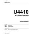
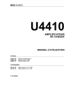
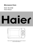
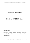
SD-W1101 DVD-RAM
with REALmagic Hollywood+ Playback Card
Installation Instructions
Congratulations on your purchase of a Toshiba SD-W1101 DVD-RAM
drive and REALmagic Hollywood+ DVD/MPEG-2 Playback Card Kit.
The following information will help you in the simple installation of
your new DVD-RAM. If you are not replacing a presently installed SCSI
CD-ROM with the enclosed DVD-RAM, additional installation hardware
may be required. Refer to REALmagic Hollywood+ User’s Guide for
installation instructions on the DVD/MPEG-2 Playback Card.
CHECKING YOUR KIT PACKAGING
Please unpack your DVD kit, and assure that you have the following
items:
l DVD/MPEG-2 PCI Playback Card (compatible with all graphics cards)
l 13” 3.5mm ext. audio cable
l 14” HDB15 - 9 DIN overlay cable
l S-Video to RCA video converter cable
l REALmagic™ Accessory Kit envelope
(with software, demo CD and Playback Card User’s Guide)
Additional items you may need that are not included in the kit are:
l Screwdriver
l mounting screws and mounting hardware
l SCSI interface cable
l SCSI host adapter board
l DVD/CD-ROM Sound Cable
SYSTEM REQUIREMENT
The DVD-RAM kit requires the following:
✔ 2MB of free hard disk space
✔ 16MB of RAM
✔ Pentium-based PC (or compatible), 133MHz or higher
✔ PCI 2.1 compliant expansion slot
✔ VGA Card
✔ Plug and Play BIOS support
✔ Microsoft™ Windows 95 or higher
✔ Amplified stereo speakers
1
1101kit.p65
1
2/10/99, 3:47 PM
The follow steps must be performed to properly install your DVD-RAM.
l Set DVD-RAM drive jumper settings.
l Connect audio cable.
l Install SCSI host adapter board.
l Attach SCSI interface cable.
l Connect power cable.
l Mount DVD-RAM.
SETTING JUMPERS
The block of mode select jumpers are located on the rear of the DVDRAM. If the jumper covers both pins
on the jumper block, it is ON; if
there is no jumper or only one of
the pins is covered, the jumper is
OFF. The jumper settings include
SCSI ID, Parity, Verify, One LUN/
Two LUN, Test, and Termination.
SCSI ID - All SCSI devices attached to
your computer are assigned a SCSI ID
number from 0 to 7. Your DVD-RAM’s
SCSI ID must be set so that its ID number does not conflict with any other
device’s SCSI ID in your system. In
most cases, your DVD-ROM will be set
to SCSI ID 4 at the factory. Also note
that your SCSI interface card in most
cases has a SCSI ID of 7. This chart
shows the jumper settings for the eight
possible ID numbers.
VERIFY
PRTY
ID1 ID2 ID4
ONE LUN/TWO LUN
TEST TERMINATION
1 2 4
ID ID ID
1 2 4
ID ID ID
SCSI-ID
0
1 2 4
ID ID ID
SCSI-ID
1
1 2 4
ID ID ID
SCSI-ID
2
1 2 4
ID ID ID
SCSI-ID
4
(default)
1 2 4
ID ID ID
SCSI-ID
3
1 2 4
ID ID ID
SCSI-ID
5
1 2 4
ID ID ID
SCSI-ID
6
SCSI-ID
7
Parity - In the OFF mode, the parity bit
check function on the SCSI data bus is
activated which enhances data bus reliability. Therefore, the jumper should
remain in the OFF mode.
Verify - When the jumper is in OFF mode, written data on the media is
verified after the write operaiton.
One LUN/Two LUN - The LUN jumper sets LUN (Logical Unit Number)
to One LUN or Two LUN mode. The default setting is no jumper present,
which sets drive to One LUN mode.
2
1101kit.p65
2
2/10/99, 3:47 PM
Test - This setting is for manufacturer use only. Do not jumper.
Terminator ON/OFF - This jumper turns termination power ON or OFF. If
you are connecting more than one SCSI device to your system, and the
DVD-RAM is not at the end of the chain, then terminator jumper is not
required.
PLACING DVD-RAM INSIDE YOUR COMPUTER
Now that you have set the jumpers, you are ready to install your DVDRAM inside your computer.
IMPORTANT: Disconnect power from your computer system before
beginning installation.
Remove computer cover and faceplate if required. Refer to your computer system’s manual for removal information. If DVD-RAM is replacing another drive (i.e., CD-ROM or DVD-ROM), remove the drive presently installed in your system.
The SD-W1101 DVD-RAM can be mounted horizontally or vertically in
any free half-height drive slot at the front of your computer.
Carefully start sliding the DVD-RAM into the opening with the disc tray
facing the front of the computer. Before you push the drive all the way in
you will need to connect the SCSI interface cable and the power cable to
the back of the drive.
CONNECTING CABLES
SCSI Interface Cable (not supplied with kit) - The internal SCSI interface cable is connected to your SCSI host adapter card and fits into the
socket on the back of your
DVD-RAM. The stripe or
red-colored side of the ribbon cable connects to pin 1
on the drive’s SCSI connector which is found next to
the drive’s power connector.
Carefully push the SCSI
connector into the socket,
making sure it fits snugly.
If you are replacing your SCSI CD-ROM: connect DVD-RAM to the
SCSI interface connector that the CD-ROM was connected to.
If DVD-RAM is an addition to a SCSI CD-ROM: daisy-chain the DVDRAM with a custom built SCSI interface cable (not supplied with kit).
3
1101kit.p65
3
2/10/99, 3:47 PM
Daisy-Chaining - If the DVD-RAM you are installing is one of two or
more SCSI devices you are connecting to your system, you will need to
use a custom built SCSI interface cable. Remember that the terminator
jumper on the DVD-RAM drive must have the jumper installed when the
drive is the last device in the chain.
Host Computer
I/F Card
Interface
Connector
SCSI Cable
DVD-RAM
DRIVE
(see note 1)
Terminator
SD-W1101 CONNECTION (ONE DRIVE)
Host Computer
SCSI Cable
SD-W1101
INTERNAL DRIVE(S)
Interface Connector
I/F Card
DVD-RAM
DRIVE
#1
(see note 2)
Terminator
DVD-RAM
DRIVE
#2
If connecting more
than three SCSI
devices, you need to
use a custom built
SCSI Interface Cable.
(see note 2)
DVD-RAM
DRIVE
#N
(N < 7)
Install Terminator Jumper
only on the last drive of BUS
(see note 1)
SD-W1101 DAISY-CHAIN CONNECTION (MULTIPLE DRIVES)
Notes:
1. Terminator jumper must be jumpered when DVD-RAM is the last
or only device on the SCSI BUS.
2. Terminator jumper should be removed when DVD is in a "daisy-chain"
and is NOT the last drive.
Power Cable - Connect an internal computer power supply cable to the power socket
at the back of the DVD-RAM.
One side of the plug has
chamfered edges, so the
power connector fits only one
way. Push plug completely
into the socket making sure
the plug fits correctly.
4
1101kit.p65
4
2/10/99, 3:47 PM
Audio Cable (optional) - If you have a sound card and speakers, and
would like to play audio CDs on your computer, you will need to get a
sound cable. Contact AMC, our small parts supplier, at 888/262-9700.
Sound cables are made for the sound card you are using and the DVDRAM to which you are connecting. Make sure you have this information
when purchasing a sound cable. The sound cable connects to your sound
card at one end and the other end connects to the digital audio connector
at the left rear of the DVD-RAM
(see DVD-RAM Back Panel photo
on page 6 for location). Refer to
the instructions which came with
your sound card for details on any
sound-driver software required.
Also refer to the REALmagic Hollywood+ User’s guide for additional audio connection options.
COMPLETING INSTALLATION
After you have connected all the necessary cables, push the DVD-RAM
completely into the computer’s drive slot. Mount drive according to
your computer’s instructions. The screw length should not exceed
3±0.5mm (measured from outside surface of side or bottom of DVD-RAM
to tip of screw). Replace computer cover and all outer screws.
,,
,,
,
Mounting Screw
M3
Mounting frame of
host computer
Surface of side or bottom
of DVD-RAM drive
2.5 - 3.5mm
Software Driver: A DVD-RAM software driver must be installed in your
system for your computer to recognize the DVD-RAM drive. You may
also be required to install software that was provided with your DVD/
MPEG card.
INSTALLING DVD-RAM SOFTWARE “WRITE DVD” (INCLUDED
IN KIT)
1.
2.
3.
4.
Insert “Write DVD” diskette into your A: drive.
Go to Start/Run and type A:\setup.exe and press OK.
Software driver will be installed.
Reboot your system.
5
1101kit.p65
5
2/10/99, 3:47 PM
USING “WRITE DVD”
After installing software, your DVD-RAM drive will be assigned two
drive letters. One will be for “read only” media (a CD icon) and the other
will be for “DVD-RAM” media ( a removable disk icon). Use your DVDRAM drive just like any other drive on your system. If you want to copy
a file from your hard drive to the DVD-RAM, just select file and drag and
drop it onto DVD-RAM removable disk icon.
DVD-RAM FRONT PANEL
The photo illustrates the following features of the SD-W1101 DVD-RAM
front panel:
① DVD loading tray
④ BUSY LED
② ROM LED
③ RAM LED
⑤ Load/Unload Button
⑥ Emergency eject hole
DVD-RAM BACK PANEL
The photo illustrates the following features of the SD-W1101 DVD-RAM
back panel:
① Analog audio out connector
② Mode select jumper
③ SCSI interface connector
④ Power connector
6
1101kit.p65
6
2/10/99, 3:47 PM
DVD-RAM RECORDING CARTRIDGE
When recording a DVD-RAM, you must use a “recording” cartridge.
There are two types of cartridges:
Type 1:
• Cartridge is reversible (side A & B).
• Disc cannot be removed from cartridge.
• Cartridges are available with single-sided* or double-sided discs.
Type 2:
• Cartridge is not reversible (side A only).
• Disc in cartridge can be removed and replaced.
* Your SD-W1101 comes with a Type 1 single-sided cartridge.
INSTALLING CARTRIDGE IN DVD-RAM
Place cartridge inside of DVD-RAM tray with label facing front of drive.
If using a single-sided DVD-RAM, make sure that side A is facing up.
TECHNICAL SUPPORT
Technical support can be obtained by calling 949/455-0407.
Drivers are available on BBS at 949/837-8864 or on our web site at
http://www.toshiba.com
FCC DECLARATION OF CONFORMITY
This equipment has been tested and found to comply with the limits for a class B digital device,
pursuant to part 15 of the FCC Rules. These limits are designed to provide reasonable protection
against harmful interference in a residential installation. This equipment generates, uses and can
radiate radio frequency energy, and if not installed and used in accordance with the instructions, may
cause harmful interference to radio communications. However, there is no guarantee that interference
will not occur in a particular installation. If this equipment does cause harmful interference to radio
or television reception, which can be determined by turning the equipment off and on, the user is
encouraged to try to correct the interference by one or more of the following measures:
• Re-orient or relocate the receiving antenna.
• Increase the separation between the equipment and receiver.
• Connect the equipment into an outlet on a circuit different from that to which the receiver is
connected.
• Consult the dealer or an experienced radio/TV technician for help.
This equipment has been certified to comply with the limits for a class B computing device, pursuant
to FCC Rules. In order to maintain compliance with FCC regulations, shielded cables must be used
with this equipment. Operation with non-approved equipment or unshielded cables is likely to
result in interference to radio and TV reception. The user is cautioned that changes and modifications
made to the equipment without the approval of the manufacturer could void the user's authority to
operate this equipment.
LASER CAUTION
This appliance contains a laser system and is classified as a "CLASS 1 LASER PRODUCT." To use this
model properly, read this Owner's Manual carefully and keep this manual for future reference. In case of
any trouble with this model, please contact your nearest "Authorized Repair Center." To prevent direct
exposure to the laser beam, do not try to open the enclosure.
7
1101kit.p65
7
2/10/99, 3:47 PM
SD-W1101 SPECIFICATIONS
Data Capacity
DVD-RAM (single & double)
DVD-R
2.42 GB
3.9 GB
DVD-ROM SINGLE SIDED-SINGLE LAYER
DVD-ROM SINGLE SIDED-DOUBLE LAYER
4.7 GB
8.5 GB
DVD-ROM DOUBLE SIDED-SINGLE LAYER 9.4 GB
DVD-ROM DOUBLE SIDED-DOUBLE LAYER 17 GB
CD-ROM
Rotational Speed
650 MB
DVD-RAM
DVD-ROM/DVD-R
1,028-2,400 rpm
1,200-2,800 rpm (single layer)
CD-ROM
1,300-3,000 rpm (double layer/DVD-R)
3,516 rpm (16X)
Transfer Rate
DVD-RAM
1,350 KB/second
DVD-ROM/DVD-R
CD-ROM
2,700 KB/second
990-2,400 KB/second (16X)
Access Time
Average Random Access Time:
• DVD-RAM
• DVD-ROM
180 ms (typ.)
260 ms (typ.)
• CD-ROM
Average Random Seek Time:
150 ms (typ.)
• DVD-RAM
• DVD-ROM
120 ms (typ.)
210 ms (typ.)
• CD-ROM
Average Start Time:
140 ms (typ.)
• DVD-RAM
• DVD-ROM
15.0 sec.
12.0 sec.
• CD-ROM
Data Buffer
7.0 sec.
256 kbytes
Acoustic Noise
Power Supply
45dB (1 meter away from drive)
+5V
Dimensions
Weight
146 x 203 x 41.3mm (W x H x D)
2.65 lbs. (1.2kg)
MTBF
100,000 hours
460017-a0
P/N 460017-A0
8
1101kit.p65
8
2/10/99, 3:47 PM