1
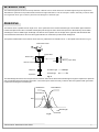
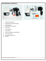
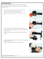
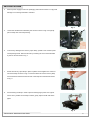
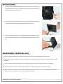
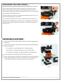
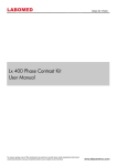
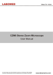
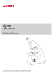
LABOMED
ideas for Vision
Lx 400 Fluorescence Attachment
User Manual
To ensure proper use of this instrument as well as to avoid injury while operating instrument,
understanding this manual completely before use is highly recommended.
www.laboamerica.com
CONTENTS
1
INTRODUCTION
1
2
PRINCIPLE
1
3
UNPACKING
2
4
SAFETY INSTRUCTIONS
3
5
INSTALLATION
4
6
MAINTAINING OPERATING LIFE
6
7
CENTERING THE LIGHT BEAM
7
8
OBSERVING A SPECIMEN
7
9
TROUBLESHOOTING
8
10
TECHNICAL SPECIFICATION
9
INTRODUCTION
The reflected light fluorescent microscope features a dichroic mirror which directs the excitation light through the objective to
illuminate the specimen and provide efficient fluorescent light observation. This microscope is used in the study of various cells
and organisms which get excited in particular wavelengths of incident light.
PRINCIPLE
The dichroic mirror is positioned at an angle of 45° to the optical axis of the incident excitation light. The excitation light is reflected
towards the objective and other unwanted wavelengths pass through the mirror. When the specimen is illuminated by the excitation
wavelength, it emits a visible longer wavelength. The dichroic mirror passes most of this light to the eyepiece while the barrier filter
mounted between the dichroic mirror and the eyepiece blocks out unwanted to provide a black background.
The spectral characteristics of the dichroic mirror when it is positioned at an inclination of 45° to the optical axis as shown in Fig. B.
Observation head
Exciter filter
Barrier filter
Mercury vapor lamp
Collector
Dichroic mirror
Objective
Excitation light
Emitted light
Specimen
Fig. A
The reflected light fluorescent microscope features a dichroic mirror which directs the excitation light through the objective the specimen
and provide efficient fluorescent light observation. The microscope is used in the study of various cells and organism which get excited
in particular wavelengths of incident light.
Reflectance
Transmittance
Absorbance
50%
lM
Wavelength
Crossover
Fig. B
Fluorescence Attachment User Guide
1
PACKAGING CONTENTS
3
5
1
6
4
8 9 10
1.
Illumination Lamp Housing
2.
Sliding Filter Block (Blue, Green & Open)
3.
Power Supply Unit
4.
Objective Set (4x, 10x, 40x, 100x)
5.
Power Cable
6.
Connecting Cable
7.
UV Rays Shield
8.
Immersion Oil Bottle (to be used with 100x)
9.
Mercury Vapor Lamp
10.
UV Ray Shield Fixation Screw
11.
Allen Key
Fluorescence Attachment User Guide
11 7
2
2
SAFETY INSTRUCTIONS
Fluorescent attachment is manufactured according to CE safety norms and regulations.
Fluorescent attachment is intended for use only as prescribed in this manual.
Make sure the main switch on the power supply unit is set to OFF (O) before supplying power to the unit.
The power supply unit contains high voltage components. Do not attempt to disassemble the unit when turned ON (I).
To avoid injury, do not remove the lamp housing while the lamp is lit. Also, do not turn the lamp ON while the lamp housing is
removed to avoid damaging the instrument.
Before opening lamp housing for replacement of the lamp, set the main switch to OFF (O) and unplug the lamp housing's
connecting cord plug from the output connector on the power supply unit. Wait at least 10 minutes or until the lamp housing
cools down before any changes are made.
Do not open the lamp housing while the system is turned ON, for any user contact with internal parts may cause injury.
A used mercury burner should be disposed of in compliance with the ordinances or regulations of your national or local
government.
The manufacturer will not accept any liability for damage caused by any user following unsafe practice of the instrument.
Avoid using the lamp beyond its service life. The mercury lamp seals high pressure gasses. If the lamp is used beyond its service life,
stress may accumulate inside the lamp and in the worst but very rare case, the lamp may burst.
Fluorescence Attachment User Guide
3
INSTALLATION
Unpack all parts from original packaging and verify that all items in packing list are
included. It is recommended that original packaging is retained for storing attachment
parts when not in use.
1.
Remove UV ray shield from its packing and attach it to the base of the
sliding filter block with the thumbscrew provided in the kit.
Fix the UV rays shield by tightening thumb screw clockwise as shown in
Fig. 2.
Fig. 1
2.
Remove observation head from dovetail adapter and fix sliding filter block in
Fig. 2
place of observation head by tightening the screw (allen key is provided in kit)
as shown in Fig. 3.
Make sure this attachment is firmly fit into the dovetail adapter and there is no
tilt or play.
3.
Replace the observation head on top of the filter block and secure by lightening
Fig. 3
thumbscrew as shown in Fig. 4.
Check for proper fitting of observation head into dovetail adapter.
Fig. 4
Fluorescence Attachment User Guide
4
INSTALLATION
4.
Remove power supply unit from its packaging and make sure there is no physical
damage to connecting terminals or switches.
Fig. 5
5.
Loosen the thumbscrew indicated by the arrow as shown in Fig. 6 and gently
pull out lamp door from lamp housing.
Fig. 6
6.
To avoid any damage to the mercury vapor lamp, a plastic rod is fitted in place
of lamp during transit. Remove this rod by loosening the two screws indicated
by the two arrows shown in Fig. 7.
Fig. 7
7.
Mount the mercury vapor lamp in place of plastic rod and tighten the screws to
secure the lamp as shown in Fig. 8. Insert the thicker end of the mercury lamp
into terminal A and insert the thinner end of the lamp into terminal B as shown
in Fig. 9.
Fig. 8
8.
Avoid touching the lamp in order to prevent leaving finger prints on the glass.
If there is any residue on the lamp's surface, gently wipe it off with soft tissue
paper.
A
B
Fig. 9
Fluorescence Attachment User Guide
5
INSTALLATION
9.
To power up the fluorescent attachment, remove the connecting cable from its
packaging and insert the three pin female connector to the input terminal of the
lamp housing door as shown in Fig. 10.
Fig. 10
10.
Next, connect the other female end of the connector cable into the male output
terminal on the rear panel of the power supply unit as shown in Fig. 11.
12.
Finally, connect the power cable from the appropriate power outlet (either 110V or
Fig. 11
220V) to the AC inlet socket on the rear panel of the power supply as shown in Fig.
12.
Fig. 12
MAINTAINING OPERATING LIFE
Ensure that the power supply unit has been connected to proper power supply voltage and line frequency.
Set the main switch on the power supply unit to (|). After the lamp is ignited, at least 5 minutes are required before the light
stabilizes.
To avoid shortening the power supply unit's operating life, avoid turning power ON while the lamp is not mounted
Avoid turning power ON and OFF within short intervals for this may reduce working life of the power supply.
After the lamp is turned OFF, it should not be re-ignited before the mercury vapors cool and condense. Wait approximately 10
minutes before turning power to the fluorescent attachment ON again.
Fluorescence Attachment User Guide
6
CENTERING THE LIGHT BEAM
First allow the mercury vapor lamp at least five minutes to fully illuminate for optimal
use (it is very important to allow the system enough time to fully ignite in order to
achieve a fully illuminated centering beam). When the lamp is fully illuminated, a
2
beam of light is visible through the beam centering window (arrow 1, Fig. 13) provided
on the front side of the sliding filter block.
1
Adjust the sharpness of this beam by adjusting the condenser knob (arrow 2, Fig. 13)
until a focused beam appears in the window.
To center this beam of light in the window, two calibrating knobs are located on the
Fig. 13
lamp housing as indicated by the two arrows in Fig. 14. By adjusting these two knobs,
the focused beam will shift. Adjust the beam position to the center of the window as
shown in Fig. 14.
Fig. 14
OBSERVING A SPECIMEN
Turn the power supply ON. Allow the lamp at least 5 minutes to fully illuminate for
optimal use.
Place the specimen slide on stage. Select the excitation light by adjusting sliding
filter block as follows :
For G-excitation - Pull filter sliding block to its outermost position.
For B-excitation - Push filter sliding block in to its innermost position.
For O light (non-excited light) - Set filter sliding block to its middle position.
Observe the specimen slide through the microscope's eyepieces.
When no fluorescent light is required, turn the attachment's power supply OFF and
set the sliding filter block to its middle / neutral position. To view the specimen in
normal condition under the microscope's light, turn the microscope ON.
Fig. 15
Fluorescence Attachment User Guide
7
TROUBLESHOOTING
Problem
Optical System
1)
The mercury lamp lights up,
but field of view remains dark
2)
Image is unclear, blurred or
has poor contrast.
3)
Field of view is vignetted or
it is not evenly illuminated.
4)
Mercury lamp is not illuminating
after switching power supply ON.
Electrical System
1)
Lamp housing / Main switch
indicator does not light up.
Cause
Remedy
Filter slider is not engaged properly
in light path.
a) Objectives and/or filters are dirty.
b) Field iris diaphragm is not
fully opened.
Adjust filter to required setting.
This process is shown on Page 7
Clean them with tissue/lens paper.
Adjust field iris diaphragm so
that the image circumscribes
the field of view.
Be sure when rotating nosepiece
that objective clicks into position.
Engage required filter
properly in light path.
Center mercury lamp correctly.
This process is shown on Page 7
Adjust the condenser knob.
This process is shown on Page 7
Press the Trigger button provided
on the front panel of power supply
unit and wait for lamp to ignite.
a)
Objective is not engaged properly
in light path.
b) Filter slider is not engaged properly
in light path.
c) Mercury lamp is not centered
properly.
d) Beam focus deviates from correct
position.
Some mercury lamps may not ignite
the first time the power supply is
turned ON.
a)
b)
2)
Main switch indicator lights up,
yet mercury lamp remains OFF.
a)
b)
3)
Light demonstrates partial
flickering.
Fluorescence Attachment User Guide
Power cord is not connected
properly.
The fuse is blown.
Connector cable is not engaged
properly.
Mercury lamp is not mounted.
a)
Sufficient time has not been
allowed for the lamp to fully
illuminate.
b)
Lamp's service life has expired.
Make sure power cord is firmly
in place.
Replace with fuse of same type
and rating.
Verify connection is secure.
Install mercury lamp as
indicated on Page 5
Allow at least 5 minutes after
turning power supply ON for the
lamp to fully illuminate. If flickering
persist press Trigger button.
Replace the mercury lamp
(part # 3127010)
8
TECHNICAL SPECIFICATIONS
Type
:
Reflected Fluorescent illumination based on slide switching of
dichroic mirror cubes
Observation modes
:
B-excitation, G-excitation and Open field (O)
Lamp type
:
HBO 100 W, high pressure Mercury vapor lamp
Supply Voltage
:
110V AC, 60 Hz / 220V AC, 50Hz
Operating environment
:
Indoor use
Ambient temperature 50 C to 400 C
Maximum relative humidity 80% at 400 C
FILTER SPECIFICATIONS
B-excitation
Excitation filter
:
Transmission 90% at wavelength 420 to 480 nm.
Transmission 0% at wavelength 485 nm onwards.
Dichroic mirror
:
Transmission 93% at wavelength 540 nm onwards
Transmission 0% at wavelength 400 to 530 nm.
Barrier filter
:
Transmission 95% at wavelength 535 nm onwards
Transmission 0% at wavelength 400 to 500 nm.
Recommended Fluorescent Dye
:
Acridine Orange, both DNA & RNA
Alternative for Fluors
:
5-Carboxyfluorescein (5-FAM)
5-Carboxytetramethylrhodamine (5-TAMRA)
5-FAM (5-Carboxyfluorescein)
Excitation filter
:
Transmission 85% at wavelength 490 to 525 nm.
Transmission 0% at wavelength 530 nm onwards.
Dichroic mirror
:
Transmission 90% at wavelength 600 nm onwards
Transmission 0% at wavelength 400 to 595 nm.
Barrier filter
:
Transmission 92% at wavelength 615 nm onwards
Transmission 0% at wavelength 400 to 575 nm.
Recommended Fluorescent Dye
:
Acridine Red FMTM 5-95
Alternative for Fluors
:
Ethidium Bromide
LDS 751 (DNA)
Nitrobenzoxadidole
.
G-excitation
Fluorescence Attachment User Guide
.
9
www.laboamerica.com
Our policy is one of continuous development. Labo America, Inc., reserves the right to change design and specifications without prior notice.
Labo America Inc.
920 Auburn Court
Fremont
CA 94538
U.S.A.
Telephone: 510 445 1257
Fax: 510 445 1317
[email protected]
LABOMED and Lx 400 are registered trademarks of Labo America, Inc.
With a policy of continuous development, Labo America, Inc. reserves the right to change design and specifications without prior notice.
© 2009 Labo America, Inc. | 9126000-990A 02-2009