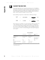
1
A
M
E
R
S
H
A
M
B
I
O
S
C
I
E
N
SE 600 Series
SE 600 and 660 Standard Dual Cooled
Gel Electrophoresis Units
User Manual
80-6353-79/Rev C3/12-99
C
E
S
S E
6 0 0
S e r i e s
U s e r
M a n u a l
1 Gel Electrophoresis Unit Function and Description
Specifications . . . . .
Important information
2 Unpacking and Inventory .
. . . . . . . . . . . . . . . . . . . . . . . .
2
3
. . . . . . . . . . . . . . . . . . . . . . . . . . . .
4
. . . . . . . . . . . . . . . . . . . . . . . .
3 Operating Instructions
3.1 Prepare the gel sandwich . . . . . . . . . . . . . . . . . . .
3.11 Construct the Gel sandwich and insert into caster
3.12 Acrylamide gels . . . . . . . . . . . . . . . . . . . . .
3.13 Gradient gels . . . . . . . . . . . . . . . . . . . . . .
3.14 Agarose gels . . . . . . . . . . . . . . . . . . . . . . .
3.15 Sample preparation and loading . . . . . . . . . . .
3.2 Final assembly . . . . . . . . . . . . . . . . . . . . . . . . . .
3.3 Separating the sample . . . . . . . . . . . . . . . . . . . . .
3.4 After electrophoresis . . . . . . . . . . . . . . . . . . . . . .
. .
7
8
10
11
12
13
14
17
19
. . . . . . . . . . . . . . . . . . . . . . . . . . . . .
20
. . . . . . . . . . . . . . . . . . . . . . . . . . . . . . . . . . .
21
4 Care and Maintenance .
5 Troubleshooting .
. . .
. . .
. .
. .
. .
. .
. .
. .
Appendices
A
B
Laemmli system gels
Bibliography . . . . .
. . . . . . . . . . . . . . . . . . . . . . . .
. . . . . . . . . . . . . . . . . . . . . . . .
24
29
Customer Service Information
Technical Service and Repair .
Ordering Information . . . . . .
i
. . . . . . . . . . . . . . . . . . . . . . . . . . . .
. . . . . . . . . . . . . . . . . . . . . . . . . . . .
30
30
S E
6 0 0
S e r i e s
U s e r
M a n u a l
Figures
Figure
Figure
Figure
Figure
Figure
Figure
Figure
Figure
1.
2.
3.
4.
5.
6.
7.
8.
SE 600 main components. . .
Gel sandwich . . . . . . . .
Clamp positions for long plates.
Club sandwich . . . . . . .
Dual gel caster assembly . . .
Pouring a gradient gel . . . . .
Upper buffer chamber assembly
Buffer chamber levels . . . . .
.
.
.
.
.
.
.
.
.
.
.
.
.
.
.
.
.
.
.
.
.
.
.
.
.
.
.
.
.
.
.
.
.
.
.
.
.
.
.
.
5
8
8
8
9
. . . . . . . 11
. . . . . . . 14
. . . . . . . 16
Tables
Table 1. Electrophoresis/caster models with gel plate sizes . 7
Table 2. Well volumes . . . . . . . . . . . . . . . . 13
Table 3. Laemmli buffer system starting point parameters . 18
ii
A m e r s h a m
P h a r m a c i a
B i o t e c h
S E
6 0 0
1
S e r i e s
U s e r
M a n u a l
Gel Electrophoresis Unit Function and
Description
The SE 600 series vertical slab gel electrophoresis units are intended for electrophoresis under both denaturing or non-denaturing conditions. Up to 28 samples
can be compared on a single slab gel.
Applications include protein separations, nucleic acid fractionation, and two-dimensional (2-D) electrophoresis. Both procedures of 2-D electrophoresis can be carried
out on the SE 600 with an adapter (ordered separately) if using carrier ampholytes
for the first dimension. If using the newly developed immobilized pH gradient (IPG)
technology, the first dimension isoelectric focusing of the sample on Immobiline®
DryStrip IPG gels is performed on the IPGphor™ Isoelectric Focusing System or the
Multiphor® II Flatbed Electrophoresis system. The focused strips are then transferred
to the second dimension slab gel for electrophoresis.
All gel plates are 18 cm wide. Table 1 on page 5 lists both models and the corresponding gel plate length (16 or 24 cm). Up to four gels can be run at one time if
sandwiches are paired into "club sandwiches." The heat exchanger allows buffer temperature control in the lower chamber.
1
M a n u a l
e
SE 600: 18 × 16 cm
SE 660: 18 × 24 cm
Gel size
SE 600: 14 × 16 cm
SE 660: 14 × 24 cm
Max. wattage
Max. voltage
Max. amperage
Max. temperature
50 W
1000 V
500 mA
45 °C
Environmental operating conditions
Indoor use: 4–40 °C
Humidity up to 80%
Altitude up to 2000 m
II
2
Installation category
Pollution degree
Dimensions
width × height × depth
SE 600: 32 × 29 × 14 cm (12.5 × 11.5 × 5.5 in.)
SE 660: 32 × 37 × 14 cm (12.5 × 14.5 × 5.5 in.)
Product certifications
EN61010–1, UL3101–1, CSA C22.2 1010.1, CE
This declaration of conformity is only valid for the instrument when it is:
2
◗
used in laboratory locations,
◗
used as delivered from Amersham Biosciences except for alterations described
in the User Manual, and
◗
connected to other CE labeled instruments or products recommended or approved by
Amersham Biosciences.
l
r
mation
➧
The safety lid must be in place before connecting the power leads to a power supply.
➧
Turn all power supply controls off and
disconnect the power leads before removing the safety lid.
➧
Circulate only water or 50/50 water/ethylene glycol through the heat exchanger.
Never introduce anti-freeze or any organic solvent into any part of the instrument.
Organic solvents will cause irreparable
damage to the unit!
➧
Do not connect the heat exchanger to a
water tap or any coolant source where
the water pressure is unregulated.
➧
Do not operate with buffer temperature
above 45 °C. All plastic parts are rated
for 45 °C continuous duty. Circulate
coolant through the heat exchanger during electrophoresis to minimize heating.
Overheating will cause irreparable damage to the unit!
➧
Only accessories and parts approved or
supplied by Amersham Biosciences
may be used for operating, maintaining, and servicing this product.
3
Informations importantes
c
➧
Le couvercle de sécurité doit être en place
avant de brancher les prises au générateur.
➧
Eteindre le générateur et débrancher les prises
avant d’enlever le couvercle de sécurité.
➧
Faire circuler seulement de l’eau ou 50/50 d’eau
et d’éthylène glycol dans l’échangeur vertical à
cirulation d’eau. Ne jamais utiliser d’anti-gel
ou tout autre solvant organique avec cet instrument. Les solvants organiques causeraient des
dommages irréparables à l’appareil.
➧
Ne pas connecter l’échangeur vertical à circulation d’eau à un robinet ou quelque source de
refroidissement dont la pression n’est pas
régulière.
➧
Ne pas utiliser avec un tampon à une température au dessus de 45 °C. Toutes les piéces en
plastique sont prévues pour résister à une température constante de 45 °C. Faire circuler l’eau
dans l’échangeur vertical durant l’électrophorèse
pour minimiser l’échauffement afin d’éviter des
dommages irréparables à l’instrument.
➧
Seulement les accessoires et piéces detachées
approuvés ou fournis par Amersham
Biosciences sont recommandés pour
l’utilisation, l’entretien et réparation de cet
appareil.
m
S E
6 0 0
2
S e r i e s
U s e r
M a n u a l
Unpacking and Inventory
Unwrap all packages carefully and compare contents with the packing list, making
sure all items arrived. If any part is missing, contact your local sales office. Inspect
all components for damage that may have occurred while the unit was in transit. If
any part appears damaged, contact the carrier immediately. Be sure to keep all
packing material for damage claims or to use should it become necessary to return
the unit.
Lower buffer chamber. The lower buffer chamber is transparent acrylic, which
allows visual tracking of electrophoresis progress. The chamber is chemically resistant to common electrophoretic buffers but not to organic solvents or strong acids
and alkali. Temperatures above 45 °C may cause the chamber to warp.
Upper buffer chamber. The upper buffer chamber is molded polysulfone, which is
chemically resistant to common electrophoretic buffers but not to organic solvents
or strong acids and alkali. The upper electrode (cathode) runs along the center
ridge, and terminates at the banana plug. The upper chamber requires
0.5–0.8 litres of buffer (fill no higher than the top of the plastic ribs).
Heat exchanger. The heat exchanger must be installed for every use because it
houses the bottom electrode (anode), which runs along the bottom of the frame.
When connected to a circulator bath, the heat exchanger regulates the buffer temperature in the lower chamber. Coolant passes through the glass tubes, which are
secured with silicone rubber grommets. The heat exchanger connector ports are
13 mm o.d. The heat exchanger is rated to a maximum of 0.8 atmospheres above
ambient (12 psig). Connect only to coolant sources under regulated pressure. (Do
not connect to the water tap.)
Safety lid. The banana plug from the heat exchanger seats into the red jack and the
plug from the upper buffer chamber seats into the black jack. The 4-mm shrouded
color-coded leads plug into color-coded jacks in the power supply. Always install
the safety lid before use!
Note
The ordering section lists
all accessories and
replacement parts.
4
Glass plates. All plates are 18 cm wide, but each model accommodates a specific
plate length: The SE 600 takes 16-cm plates, and the SE 660 takes 24-cm plates.
Six smooth glass plates are included with each unit. Frosted plates (16 cm length)
can be ordered separately for agarose gels. (The rough surface prevents agarose
gels from slipping out of the sandwich.) Notched divider plates, ordered separately, pair two gel sandwiches to form a “club sandwich” so that up to four gels can
be run at one time.
A m e r s h a m
P h a r m a c i a
B i o t e c h
Color-coded leads (2)
Figure 1. Main components
SE 600 series
(see Fig. 5 for caster
components)
Safety lid
Included but not shown:
GelSeal,1/4 oz.
Spacer-Mate
Well-locating decal
Upper buffer chamber
with upper electrode
Glass plates (6)
Complete unit also includes
spacers (4) and combs (2)
Required but not included:
Magnetic stirrer
Power supply with a minimum rating of 500 V,
100 mA (constant A or V)
Heat exchanger
with lower electrode
Optional:
Circulator bath
Lower buffer chamber
ich. An additional
he clamp pressure
bar, adjusted with screws, distributes pressure evenly.
Casting stand. The casting stand holds assembled gel sandwiches upright for casting gels. Adjustable feet level the caster. A laminated gasket in the bottom of each
casting cradle seals the bottom of the sandwich when it is cammed into the stand.
Cams. Cams are used twice: first, to secure the assembled sandwich in the casting
stand and second, to attach the sandwich to the upper buffer chamber.
5
M a n u a l
Rubber gaskets. There are two sets of two gaskets: The solid laminated gaskets fit
into the bottom of the casting stand and provide the seal for casting the gel. The
slotted gaskets fit under the upper buffer chamber and provide the seal between
the upper and lower chambers. The ridges position the gasket to align the slot to
expose the gel to the buffer in the upper chamber.
Spacers. (May be ordered separately.) Spacers determine the thickness of the gel
and are available in three thicknesses (0.75, 1.0, and 1.5 mm) and two widths
(1.0 and 2.0 cm).
Spacer Mate™ assembly template. Aligns spacers for sandwich assembly.
Combs. (May be ordered separately.) Teflon combs are available in sizes that form
10, 12, 15, 20, or 28 wells. Most combs are available in all three thicknesses:
0.75, 1.0, and 1.5 mm. Blank combs form a single large well, and preparative
combs include 1 or 2 reference wells in addition to the preparative well.
All blanks, preparative combs, and 10-, 12-, 15- and 20-well combs form wells
that are 25 mm deep. The 28-well comb forms wells that are only 15 mm deep so
that wells do not collapse when the comb is removed. The sample volume held by
each well depends on the gel thickness, well depth and the number of wells per
comb. Table 2 lists sample volumes of each well for all combs.
WonderWedge Plate Separator Tool. Used to disassemble gel sandwiches and to
gauge spacer and comb thickness.
2-D electrophoresis, use
spacers the same size as
the tube gel to ensure a
good fit.
Two-dimensional electrophoresis. The SE 600 can be adapted to a 1.5-mm
2-D system with the SE 600 Series Tube Gel Adaptor Kit (ordered separately).
Tube gels are first cast and then transferred to the tube gel adaptor, which holds
the tubes. After electrophoresis, tube gels are extruded onto slab gels. The second
dimension separation is then also run in the same unit. (For details, refer to the
Tube Gel Adapter Kit instructions.)
First dimension isoelectric focusing of Immobiline DryStrip IPG strips require the
IPGphor Isoelectric Focusing System or the Multiphor II Electrophoresis System.
Details of each procedure are described in the respective protocol guide (see the
ordering information section). The SE 600 is especially suited to perform the second dimension on thicker gels, which are required to handle high sample loads.
6
S E
6 0 0
3
3.1
S e r i e s
U s e r
M a n u a l
Operating Instructions
Gel casting and electrophoresis procedures follow. Assembly of both models is
identical. Included are instructions for polyacrylamide gels (used with continuous
or discontinuous buffer systems), gradient gels, and agarose gels. See Appendix A
for recipes and Appendix B for a bibliography.
Prepare the gel sandwich
Glass plates, spacers, and clamp sets are sized so that the assembled sandwich can
be easily aligned to create the seal required first to cast the gel and then to run it.
For best results, take extra care to align all components when assembling sandwiches.
Table 1 summarizes gel casting options.
SE 600
Both precast gels and self-cast gels can be used. To self-cast multiple gels, kits can
be ordered separately: the SE 615 Multiple Gel Caster Kit holds up to 10 sandwiches, and the SE 675 Gel Caster Kit holds up to four sandwiches. (See the
accompanying gel caster user manual for complete instructions.)
SE 660
The 24-cm gels required for the SE 660 must be self-cast. The Dual Gel Caster
(included) holds two gel sandwiches.
Table 1
Model
no. of gels
gel plate size (cm)
available gels and casters
SE 600
1–4*
18 × 16
Dual Gel Caster,
Gel Caster Kit§
Multiple Gel Caster Kit†
Commercially available gels
SE 660
1–4*
18 × 24
Dual Gel Caster
*Two accessory notched divider plates are required to run 2 extra gels
§
Casts up to 4 gels
†
Casts up to 10 gels
7
S E
6 0 0
3.11
Figure 2.
Sandwich assembly
Inspect glass plates for
nicks. Use only unchipped
plates to prevent leaking.
Figure 3.
Required number of clamps
SE 600
SE 660
S e r i e s
U s e r
M a n u a l
Construct the gel sandwich and insert into caster
1
Prepare the caster and clamps. Place the spirit level into the caster center and
adjust the leveling feet. Loosen all clamp screws and make space for the sandwich by sliding the pressure plates toward the screws.
2
Construct each gel sandwich. (Agarose gels: also see section 3.14.) For each
sandwich, choose two perfectly clean unchipped glass plates and two spacers.
Lay one plate on a flat surface, lay the Spacer Mate assembly template onto
the plate (wide side at the top of the plate), place a spacer along each edge,
and lay the second glass plate on top.
3
Secure the sandwich with clamps.
Slide one clamp at a time along
the sandwich sides. Finger tighten
one screw on each clamp, set the
sandwich upright on a flat surface, and loosen the screw to align
the stack. Take great care in
aligning to ensure a seal. Finger
tighten all screws. Remove the
Spacer Mate.
Pressure bar
Both top and bottom
sandwich edges must
be flush with the
clamp guide ridges.
Tip: Use the casting cradle to hold the sandwich during alignment. Remove
the laminated gasket from the cradle and, instead of setting the sandwich
upright on a flat surface, set it into the casting cradle.
Clamp size
8 cm
16 cm
2
2
2
16 cm
SE 600
24 cm
SE 660
Long sandwiches require two clamp assemblies on each side. When assembling 24-cm
sandwiches, align each end separately.
That is, align one end, finger-tighten the
screws, turn the sandwich 180° and align
the other end. In each case allow the clamp
to slide down and align perfectly with the
top (or bottom) edge of the glass plates.
Club sandwich
A 16- or 24-cm long, notched-center divider plate (ordered separately) pairs
two sandwiches to double the number of gels that can be cast and run.
Figure 4.
Club sandwich
assembly
Only thinner gels can be
paired; no spacers thicker
than 1.5 mm can be used.
8
Assemble a club sandwich in the
same manner as a regular sandwich, except before laying the top
glass plate, lay the divider plate
and a second set of spacers. Place
the notch so that it will be at the
top of the gels. It is essential that
the spacers and plates align perfectly in order to create a seal. For
24-cm long plates, position the
8-cm clamp along the side at the
bottom of the sandwich farthest
from the notch.
Glass plates
(at the outer sides
of the sandwich)
Notched
center plate
Spacers
S E
6 0 0
S e r i e s
5
U s e r
M a n u a l
Remove the sandwich and inspect the bottom to make sure that edges are
aligned flush in order to ensure a complete seal. Adjust if necessary.
Optional: Apply a light film of GelSeal only on the bottom corner surfaces
created by the spacers and plates if your sandwiches tend to leak.
Note
Do not use silicone grease
or petroleum jelly to seal
the sandwich.These substances are difficult to
remove and ultimately
cause artifacts.
6
Place the laminated gasket into the casting cradle (See Figure 5) with the
foam side down. Place the clamp assembly in the casting cradle, screw side
facing out. For 24-cm plates, place the sandwich so that the longer clamp is at
the top.
7
Insert a cam into the hole on each side of the casting tray with the ridge
(short end) pointing up. Seal the gel sandwich by turning both cams as far as
needed, usually 90° to 150°, up to 180°. The camming action presses the
plates into the gasket and thereby seals the bottom of the sandwich. The seal
is complete once the glass edge appears darker and nearly transparent against
the gasket. Do not cam past this point.
Figure 5.
Caster components and set up
Glass plates
Spacers
Gasket
(foam side
faces down)
Clamps
(The number required depends
on the plate length.)
Casting cradles (2)
Note
When turning the cams, it
is easier to keep the caster
balanced if you turn both
toward the center of the
caster.
Spirit level
Levelling feet (4)
Cams
(Install ridge end up)
9
S E
6 0 0
3.12
S e r i e s
U s e r
M a n u a l
Acrylamide gels
1
Prepare the monomer solution and pour the gel. Prepare the required amount of
monomer solution. De-aerate and add the initiator and catalyst just prior to
pouring the gel. Pipet the solution into one corner of the sandwich, taking
care not to introduce any air bubbles. See below for the appropriate solution
level according to the application.
No stacking gel
(Continuous system) Fill solution to just below the top
of the upper plate edge. If bubbles are trapped, remove
with a pipet or syringe. Introduce a comb (at a slight
angle) into each sandwich, taking care not to trap air
bubbles under the teeth.
Club sandwich
Pipet the solution into both sandwiches, filling each to
the same level below the notched edge.
Stacking gel
Fill solution to 3–4 cm below the top of the glass plate.
This height allows 1 cm of stacking gel below the
wells. Pour the gel and apply an overlay (see step 2).
After the gel is set, prepare the stacking gel as
described below.
2-D electrophoresis
(Discontinuous system) Fill solution to about 1 cm
below the top of the glass plate to allow 4 to 5 mm for
the IPG strip or tube gel and an agarose seal. (A stacking
gel will require extra space). Seal the IPG strip or tube
gel in place with agarose dissolved in running buffer.
Take care to avoid trapping any air bubbles between the
first and second dimension gels.
Note
Appendix A lists recipes for
the Laemmli gel system.
2
Overlay each gel with a thin layer of water-saturated n-butanol, water, or
diluted gel buffer to prevent gel exposure to oxygen. Slowly deliver the overlay solution from a glass syringe fitted with a 22-gauge needle. Apply the
solution near the spacer at the side of the sandwich and allow it to flow
across the surface unaided.
3
Allow the gel to polymerize for a minimum of one hour.
Stacking gel preparation
Pour the stacking gel while the sandwich is still in the gel caster. Stacking gel resolution is optimal when poured just before electrophoresis.
1
Remove the overlay by rinsing the top of the gel several times with distilled
water. Invert the caster to drain. To ensure a seamless contact between the
resolving and stacking gels, remove residual liquid by blotting one corner with
a lint-free tissue.
2
Calculate the stacking gel monomer solution volume.
3
Prepare the stacking gel monomer solution, deaerate it, and add catalyst and
initiator. Pour the stacking gel onto the resolving gel with a disposable or
Pasteur pipette to a level about 2 mm from the top of the plate.
4
Introduce a comb (at a slight angle) into the sandwich, taking care not to trap air
under the teeth. Allow a minimum of one hour for the gel to polymerize.
10
A m e r s h a m
P h a r m a c i a
B i o t e c h
S E
6 0 0
3.13
S e r i e s
U s e r
M a n u a l
Gradient gels
Both linear and exponential gradient gels can be poured in the dual gel caster. We recommend using a SG Series Gradient Maker. Gradient gels are poured from the
top of the caster with a cannula if using the provided dual gel caster or from the bottom
if using a Multiple Gel Caster (see instructions accompanying the caster). A
stacking gel is then poured over the gradient gel.
Pouring a linear gradient gel
Figure 6.
Pouring a gradient gel
1
Assemble sandwich(es) into the dual gel casters as described in section 3.11.
2
Set up the monomer solution flow
path. Run a length of Tygon tubing through a peristaltic pump.
Attach one end of the tubing to the
gradient maker outlet port and the
other end to an 8-inch cannula.
(The OD of the cannula must be
less than the spacer thickness.)
Place the cannula so that it rests at
the bottom of the sandwich, midway between the spacers.
3
Prepare the monomer solution. Calculate the volume of monomer solution need-
Alternatively, the gel solution may be introduced
into the gel sandwich
through a pipet tip at a
rate that maintains a continuous stream.
Note
Gradient gels poured in
the SE 615 or SE 675
Multiple Gel Caster are
introduced through the
bottom.
ed. Divide the total volume in half and prepare this volume of both the higher
and lower % acrylamide solutions. (Optional: Add 15% sucrose or 25% glycerol, final conc., to the higher % solution to improve layering.)
4
Note
When pouring an exponential gradient gel, position a
plunger above the liquid to
hold the volume in the
mixing chamber constant.
Pour the "light" solution into the reservoir chamber (the chamber furthest
from the inlet). Open the stopcock long enough to displace air between the
chambers and then close. Pour the "heavy" solution into the mixing chamber
and place a stirring bar into this chamber. Place the gradient maker onto a
magnetic stirrer and begin stirring at a rate that does not introduce bubbles in
the solution.
5
Mix the gradient and pump the solution into the sandwich. While the solution is
stirring, begin pumping from the mixing chamber and open the stopcock to
the reservoir chamber. Raise the cannula as liquid enters the sandwich, keeping the tip at the gel surface. Prepare more gels as required.
6
Overlay each gel with a thin layer of water-saturated n-butanol, water, or diluted
gel buffer to prevent gel exposure to oxygen. Slowly deliver the overlay solution
from a glass syringe fitted with a 22-gauge needle. Apply the solution near the
spacer at the side of the sandwich and allow it to flow across the surface unaided.
7
Allow the gels to polymerize for a minimum of one hour. After polymerization,
pour off the overlay and rinse the gel surface several times with distilled water.
8
Prepare the stacking gel monomer solution, pour the stacking gel and introduce
a comb (at a slight angle) into the sandwich, taking care not to trap air under
the teeth. Allow a minimum of one hour for the gel to polymerize.
A m e r s h a m
P h a r m a c i a
B i o t e c h
11
M a n u a l
3.14
Assembling the gel sandwich
Follow the general assembly instructions with the following exception:
Use one (or two) frosted glass plates instead of smooth glass plates. Use one
frosted and one clear plate if blotting the gel after electrophoresis. Place the
membrane against the smooth (clear glass) side of the gel. Or, use two frosted
plates for more secure retention of the gel between the plate while handling.
Frosted plate code numbers
SE 600
SE 660
80-6179-37
not available
Assemble the sandwich so that the frosted side faces inward. Orient the sandwich so that the only frosted edge is at the bottom. (The smooth side edges
ensure a better seal between the spacers and the plate, and the smooth top
allows easy removal of the comb.)
Casting agarose gels
Follow casting instructions with the following exceptions:
1
Warm a 25-ml pipet, the casting stand and the assembled gel sandwiches in
an oven set to 45 °C. This assures that the agarose stays liquefied while being
handled.
2
Melt the agarose and cool to 75 °C before transferring it with the warmed
pipet into the warmed sandwiches.
3
Insert a comb in each sandwich to a depth of no more than 1 cm. Deeper wells
are easily damaged when removing the comb. Allow the agarose to gel. (The
adjustable comb back aids in placing combs.)
Loading the sample
Follow the loading instructions in section 3.15. Take great care to not damage the
wells when removing the combs. Combs may slide out more readily if distilled
water or buffer is added to the well area. “Walk” the comb out by gently rocking
the comb (from spacer to spacer) and lifting it straight up.
12
S E
6 0 0
3.15
S e r i e s
U s e r
M a n u a l
Sample preparation and loading
The sample can be loaded either while the sandwich is in the caster or after the
upper buffer chamber is attached.
Note
With Coomassie Blue, it is
possible to detect 1 µg in
a single band. With the
more sensitive silver
stains, it is possible to
detect as little as 10 ng.
The amount of sample loaded depends on the thickness of the gel, the sensitivity of
the detection method used, and the amount of sample expected in each band. In a
continuous buffer system, the protein sample should be relatively concentrated
because no stacking gel is used. In a discontinuous buffer system, the zone into
which each molecular species migrates is sharpened by the stacking gel so the sample need not be as concentrated.
1
Prepare the wells. Remove the comb by gently rocking it side to side and then
lifting it straight up to avoid damaging the well walls. Carefully rinse each
well with distilled water to remove unpolymerized acrylamide and then drain
by inverting the gel sandwich (or caster). Fill each well with electrophoresis
buffer.
2
Prepare the sample. Increase liquid sample density with 10% glycerol or
sucrose. Add a tracking dye such as phenol red, bromphenol blue, or
pyronin y.
For SDS protein gels, use 2X treatment buffer to denature both liquid and dry
samples in a test tube.
To liquid protein solutions, add an equal volume of 2X buffer.
To dry protein samples, add equal volumes of 2X sample buffer and ddH2O
to achieve the desired concentration.
Note
Once the sample is in the
wells, take care to not jar
the sandwiches so that the
samples are not disturbed.
3
Heat the tube in boiling water for 90 seconds, then allow to cool to room temperature. Treated samples can be stored at -40 to -80 °C for future runs.
Heat membrane proteins to 60 °C for 20 minutes. Store unused sample at
4 °C.
4
Underlay the sample into the wells using a fine-tipped microsyringe or gel
loading pipet tip.
Table 2
Sample volume for each
comb size
Volume of sample (µl) per 1 mm depth
No. of
wells
10
12
15
20
28
13
Comb thickness (mm)
0.75
1.0
6.2
5.8
4.3
3.1
2.1
8.3
5.7
4.1
2.7
1.5
12.4
11.5
8.6
6.2
4.1
S E
S e r i e s
6 0 0
3.2
U s e r
M a n u a l
Final assembly
Upper buffer chamber
1
Rinse both buffer chambers with water and distilled water thoroughly before
each use. Note: Before using the first time, disassemble the unit and wash
with a dilute solution of a laboratory detergent and rinse thoroughly first
with water and then distilled water.
Clean away any gel adhering to the exterior of the gel sandwiches.
2
If running only one gel: Block the second upper buffer chamber slot by
installing the acrylic buffer dam included with the unit. Fit clamps onto the
dam, taking care to align the clamp ends and dam edges. Install the
“dummy" gel, screws facing out, in the second cradle in the dual gel caster.
Note
To help hold the gasket
against the upper buffer
chamber, dab a small
amount of GelSeal at each
end of the gasket only and
then install.
3
Attach the gel sandwich to the upper buffer chamber.
Turn the upper buffer chamber upside down and place a slotted gasket into
both sandwich holder recesses. Both the slot in the gasket and the slot in the
recess must align. Grooves along each slot help keep the gasket in place.
Release the sandwiches from the caster by removing all bottom cams (if present). Lower the upper buffer chamber onto the gel sandwiches in the casting
stand. Install the cams, ridge pointing down, into the buffer chamber cam
holes. Cam the sandwich in place by simultaneously turning one cam clockwise and the other counterclockwise a full 180°.
Important
A smooth fit between the
sandwich and gasket is
essential to a good seal.
Note: Do not force the cams. If encountering unusual resistance, disassemble and
inspect clamp and glass alignment along the top of the sandwich. Align and reinstall.
4
Use a pipet to carefully fill each slot above the sample wells with buffer in
order to minimize disturbing the samples. Then pour 100 ml of buffer into the
chamber, directing the buffer stream toward the side wall. Check that no
buffer is leaking.
Figure 7.
Attaching gel sandwiches to
the upper buffer chamber
If the assembly leaks, take
it to a sink and partially
release the cams to allow
buffer to drain out of the
upper chamber.
Disassemble, check alignment of all sandwich components, and adjust if
necessary.
A Remove cams from the lower
cam holes. Place the upper
chamber onto the sandwiches
and then insert the cams into
the upper cam holes, ridge
(short end) pointing down.
B The final cam position (not
shown) must be vertical so that
the assembly fits into the lower
buffer chamber.
14
l
Important assembly notes
◗
IEF runs: the buffer level in the lower buffer chamber must never reach the upper
buffer chamber; allow at least 2 cm clearance.
Do not fill the upper or lower chamber above the recommended levels illustrated
on the next page. Avoid buffer contact with the electrode posts.
Pour buffer slowly and away from the slots in the upper buffer chamber to avoid
disturbing the samples.
Use only water or 50/50 water/ethylene glycol as coolant. Never use a commercial
antifreeze or any alcohol-based mixture or irreparable damage to the heat
exchanger will result.
Do not connect the heat exchanger to a water tap or any other source where the
water pressure is unregulated.
◗
◗
◗
◗
Lower buffer chamber
1
Place a magnetic spin bar into the lower chamber and place the unit on a
magnetic stirrer. Partially fill the lower chamber.
2
Lower the heat exchanger into the lower chamber, fitting the ports into the
notches in the rim. (The heat exchanger must be in place for every run
because the lower electrode is integrated into the heat exchanger.) If no cooling is required, skip to step 3.
Connect the heat exchanger to a thermostatic circulator such as the
MultiTemp III. Slide hose clamps (4 total) onto each end of two lengths of
10–12 mm i.d. (3/8–1/2") vinyl or silicone tubing. Attach one end of each length
of tubing to a heat exchanger port. Attach the free ends of each length of tubing to the circulator bath ports; one to the inlet and the other to the outlet.
Secure the connections with the hose clamps.
venient to attach Quick-fit
connectors to the tubing.
The valves in these fittings
prevent coolant spillage.
Use the chart below to estimate a starting point for the circulator bath temperature setting. Adjust as necessary for variables such as ambient temperature, changes in power output, and circulator bath efficiency. If accurate temperature control is critical, measure the temperature and adjust as necessary.
Optional - Prechill the buffer.
Example
0
Run parameters
200 V, 0.05 A (50 mA)
-1
Bath setting correction, °C
Approximate
circulator bath
temperature setting
Set the circulator bath
temperature setting lower
than the desired run temperature by the amount
indicated on the graph.
1 Calculate W if your power supply
does not display power directly:
W=VxA
10 W = 200 V x .05 A
-2
-3
2 Interpolate the number of degrees
to subtract from the desired run
temperature.
-4
-5
10 W intersects the graph at about
-1 °C.
-6
-7
0
10
20
30
40
Power supply setting, W
15
50
60
If the desired temperature is 23 °C,
set the bath to 23 -1 = 22 °C.
If the desired temperature is 4 °C,
set the bath to 4 -1 = 3 °C.
S E
6 0 0
S e r i e s
U s e r
M a n u a l
3
Fit the upper buffer chamber assembly into the lower buffer chamber. Use a
steady hand to avoid disturbing the samples: Grasp the assembly in the casting stand by the upper buffer chamber and carefully lower it into the lower
buffer chamber.
4
Inspect the installation and check the buffer levels.
Upper chamber. The electrode along the upper chamber ridge must be submerged about 1 cm. This level requires 450– 600 ml buffer: just enough to
cover the upper chamber ribs, but not high enough to contact the banana
plug.
Lower chamber. The lower buffer level depends on running conditions and the
buffer system as described below.
Figure 8.
Buffer chamber levels.
◗ Low voltage runs
Approximate volumes required:
◗ Systems using the same
buffer in both the upper
and lower chambers
SE 600
4.5 liters
SE 660
7.0 liters
Upper and
lower chamber
buffer levels
are equal
—or—
◗ High voltage runs
Approximate volumes required:
◗ Isoelectric focusing
SE 600
4.0 liters
◗ Systems using different
buffers in the upper
and lower chambers
SE 660
6.0 liters
Upper chamber
buffer level
Lower chamber
buffer level
The buffer level should
cover most of the gel
sandwich (to allow the dissipation of heat) but must
allow at least 2 cm clearance below the upper
buffer chamber.
5
Place the safety lid on the unit.
6
Plug the color-coded leads into the jacks of an approved power supply, such as
the EPS 601. Plug the red lead into the red output jack and the black lead into
the black output jack. In most systems, the red lead, which is connected to the
bottom electrode, is the anode (+), and the black lead, connected to the top
electrode, is the cathode (–).
16
A m e r s h a m
P h a r m a c i a
B i o t e c h
S E
6 0 0
3.3
S e r i e s
U s e r
M a n u a l
Separating the sample
Electrophoresis parameters for discontinuous polyacrylamide gels
Note
All SE 600 series models
use 18-cm wide plates.
The gel thickness determines the cross section
(and current requirement)
The length of the plate
determines the running
time.
Gels may be run at either constant current or constant voltage settings. A constant current setting is traditionally used with a discontinuous buffer system so that the rate of
electrophoretic migration remains unchanged throughout the run. Under these conditions, voltage increases as the run proceeds. A lower current setting is recommended
for higher resolution. The optimal current level must be determined empirically; the
main factors that must be balanced include the gel concentration and migration speed,
and the resulting Joule heating and band distortion. Table 3 on the next page lists
starting point guidelines and adjustments for gel thickness, number of gels, and
migration rate.
Current
Current acts on the total cross-sectional area of all the gels, and in terms of a circuit, the gels are considered to run in parallel. Therefore, any current setting for
one gel must be multiplied by the number of gels run. For a gel 1.5 mm thick, we
suggest a starting point current setting of 25 mA. (Two 1.5 mm gels = 50 mA.)
Note: Cooling may be required to control Joule heating.
Voltage
The starting voltage for a 1.5 mm slab gel connected to a power supply set to 25 mA
is usually 80 to 90 V (using the SE 600 with a Laemmli discontinuous buffer system
for SDS gels). The final voltage is typically 250 to 400 V, depending on the length of
the gel. (See Table 3.)
Time
A run is complete when the tracking dye reaches the bottom of the gel. In a 16-cm
gel (SE 600), a 1.5-mm thick Laemmli SDS gel, run at 25 mA/gel without cooling,
usually requires 5 hours. Longer gels require proportionally more time; separations
in 24-cm gels (SE 660) require 8 hours.
Electrophoresis parameters for agarose and DNA/acrylamide gels
Agarose gels are usually run at a constant voltage setting, and since agarose buffer
systems are continuous, both current and voltage readings remain constant throughout the run. Running conditions are expressed in units of V/cm. This allows electrophoresis results from both vertical and horizontal units to be compared. Published
running conditions vary widely, but voltages in the range of 1 to 3 V/cm are common for overnight runs. In the SE 600, we have run gels at up to 12.5 V/cm.
(Cooling is required at this voltage level.)
A m e r s h a m
P h a r m a c i a
B i o t e c h
17
S E
6 0 0
S e r i e s
U s e r
M a n u a l
Record each run
Keep a record of the current or voltage setting, number and thickness of gels,
buffer system, and the starting and final current or voltage readings for each run
so that results can be compared. Inconsistent results for the same system and settings indicate potential problems such as leaking current, incorrect buffer concentrations, high salt concentrations or inconsistent chemical quality.
Table 3.
Laemmli buffer system starting point guidelines
Gel thickness*
Current per gel†
§
Starting voltage
Model
1.5 mm
25 mA constant current
80–90 V
SE 600
gel length
(cm)
16
final
voltage (V)
200–250
SE 660
24
275–325
*Thicker or thinner gels require proportionally more or less current. For
example, a 0.75-mm gel , which is half as thick as a 1.5-mm gel, requires half
as much current, or 12.5 mA.
†
The current must be multiplied by the number of gels. For instance, if two
club sandwiches are installed, the 4 gels require 4 times as much current. The
current can be increased for faster runs if active cooling is used, and it can be
decreased for slower overnight runs.
§
Caution
After initial monitoring, do
not leave the unit
unattended for more than
1 hour before checking the
progress of the bands and
the buffer level.
At 25 mA per gel.
Check band progress after 5 minutes, and again after an hour, keeping an eye on
the migration rate of the tracking dye. The run is complete when the tracking dye
reaches the bottom of the gel. Watch the buffer level and, if necessary, replenish it
as required to keep the top electrode submerged. (A small volume of buffer may
leak past a nicked plate or gasket, or buffer may pass through the gel.)
Refer to Appendix A for buffer recipes and electrophoretic conditions.
18
A m e r s h a m
P h a r m a c i a
B i o t e c h
S E
6 0 0
3.4
S e r i e s
U s e r
M a n u a l
After electrophoresis
1
Once the tracking dye reaches the bottom of the gel, turn off the power supply, disconnect the leads and remove the safety lid, using finger leverage
between the lid and the top of the heat exchanger. (Lift straight up to avoid
bending the banana plugs.)
2
If coolant is circulating, stop the flow and disconnect the fittings or tubing.
3
Pull out the upper buffer chamber assembly. Pour out the buffer by inverting
the upper buffer chamber over a sink. Install the assembly in the dual gel
caster and then release the sandwiches by removing the cams.
4
Note
Use only flexible plastic
prying tools to avoid chipping the glass plates.
slide away both spacers. Use the Wonder Wedge plate separator tool to
separate the plates.
5
Carefully lift one glass plate. Handle the gel with care to avoid damaging it.
Invert the plate and position the gel low over the stain tray. Lift one corner of
the gel and allow it to drop into the tray, or, if the gel is thick enough to handle, lift it and place into the tray. To avoid splashing, add staining or fixative
solution to the tray after the gel is transferred.
6
19
Unscrew the clamps from the sandwiches and remove. Gently loosen and then
Clean the unit as described in the next section.
S E
6 0 0
4
S e r i e s
U s e r
M a n u a l
Care and Maintenance
Cleaning
◗
Do not autoclave or heat any part above 45 °C.
◗
Do not use organic solvents, abrasives, strong cleaning solutions, or strong acids
or bases to clean the chambers.
◗
Do not soak the laminated gasket.
Immediately after each use, rinse the upper and lower buffer chambers with water
and then rinse thoroughly with distilled water. Handle the upper buffer chamber
with care to prevent damage to the banana plug. Clean gaskets with mild detergent
and rinse with distilled water. Allow to air dry.
Clean glass plates and spacers with a dilute solution of a laboratory cleanser such
as RBS-35®, then rinse thoroughly with tap and distilled water. Glass plates can
also be treated with (but not stored in) acid cleaning solutions.
Replacing a heat exchanger glass tube
Note: If the old tube is cracked or broken, protect your hand with thick gloves, a
piece of cloth, or paper towel before removing the tube.
1
Remove the tube by simultaneously twisting and sliding it down as far as possible, until the top end is free of the upper grommet. Carefully guide the tube
so that it will clear the assembly, then lift the tube out of the lower grommet.
2
Lightly grease the outside of both ends of the new tube with silicone grease.
Twist and slide one end of the tube into the lower grommet. Then, slip the
other end into the top grommet, gently pushing it with a slight twist into the
top grommet until it stops.
3
20
Check that the grommet is not pinched.
S E
6 0 0
5
S e r i e s
U s e r
M a n u a l
Troubleshooting
Gel sandwich leaks while casting
✓
✓
✓
✓
✓
✓
Plates, spacers, and the gasket must be completely clean. Wash if necessary.
Replace chipped plates. (Especially if chipped near the spacers.)
Check plate and spacer alignment and realign if necessary.
Cam only as far as necessary to create a seal (usually 90–150°, but up to
180°).
Apply a light film of GelSeal to the bottom outside corner only of each
spacer. Do not use silicone grease.
Check the caster gasket for cuts or cracks and replace if necessary.
Sample wells damaged or irregular
✓
✓
✓
✓
✓
Remove air bubbles before inserting combs. Slide comb into solution at
an angle. If comb must be removed, add more monomer solution before
reinserting the comb.
Allow acrylamide gels to set for a minimum of 1 hour.
Rinse out unpolymerized gel with sample buffer.
Remove the comb at a slight angle and very slowly to prevent damage to
the gel.
Agarose gels: Lower the comb no more than 1 cm into the gel.
Incomplete gel polymerization
✓
Use only recent stock of the highest quality reagents.
✓
If the dry ammonium persulfate does not crackle when added to buffer,
replace with fresh stock.
✓
Solutions with extreme pH values (especially acidic) may not polymerize.
✓
Remove oxygen from the gel environment: Degas the monomer solution
5 to 10 minutes before pouring and then overlay the gel surface with
water-saturated n-butanol.
✓
Adjust the gel solution temperature to a minimum of 20 °C, especially
for low % T gels.
✓
Increase TEMED or APS concentration, or both.
Upper buffer chamber leaks
✓
✓
✓
Check that the glass plates, spacers, and clamps are aligned and fit snugly
into the upper chamber gasket.
Check that both gaskets are centered and that the positioning ridges fit
inside the grooves.
Check that the gasket is not damaged or pinched.
Power supply detects current leak
✓
✓
A m e r s h a m
Add more silicone grease to seal heat exchanger grommets.
Check for leaks or cracks in the heat exchanger. Replace worn grommets.
P h a r m a c i a
B i o t e c h
21
S E
6 0 0
S e r i e s
U s e r
M a n u a l
Dye front curves up (smiles) at the edges
✓
✓
✓
✓
✓
Fill the lower buffer chamber to the level appropriate for the run. (See
section 3.2.)
Circulate coolant.
Prechill the buffer.
Decrease the current or voltage setting.
Run the gel in the cold room.
Protein streaks vertically
✓
✓
✓
✓
Centrifuge or filter sample before loading to remove particulates.
Dialyze or desalt the sample.
Load less sample.
Add protease inhibitor, such as PMSF.
Unusually slow (or fast) run
✓
✓
Check for leaks; all plates and spacers must be aligned and free of grease.
If used, the buffer dam must be secure.
Adjust the solutions
✓
✓
✓
✓
✓
If the required pH of a solution is exceeded, do not back-titrate. Prepare
fresh buffer.
Check recipes, gel concentrations, and buffer dilution. (For instance, do
not use Tris-HCl instead of Tris for Laemmli tank buffer.)
Dispose of older acrylamide solutions and use only stock of the highest
quality.
Only use freshly deionized urea.
Decrease the salt concentration of samples.
Adjust the voltage or current settings
✓
To increase or decrease the migration rate, adjust the voltage or current
by 25–50%.
Bands are skewed or distorted
Check gel preparation and polymerization
✓
✓
Degas the stacking gel solution and avoid trapping air bubbles under the
comb teeth.
Overlay the running gel with water-saturated n-butanol before polymerization begins to avoid forming an uneven gel surface.
Check sample preparation
✓
✓
Dialyze or desalt the sample.
Centrifuge or filter sample before loading to remove particulates.
Protein bands are diffuse or broader than usual
✓
✓
✓
✓
✓
22
Use only high quality acrylamide and bis.
Ensure that polymerization is complete.
Fully equilibrate sample.
Make fresh sample buffer. Add a protease inhibitor such as PMSF.
Reduce TEMED or APS concentration.
A m e r s h a m
P h a r m a c i a
B i o t e c h
S E
6 0 0
S e r i e s
U s e r
M a n u a l
Stained sample collects:
Near the buffer front
✓
✓
Molecules are not sufficiently restricted by the resolving gel pore size;
increase the %T.
Proteins may be degraded by endogeneous proteases; use protease
inhibitors during the isolation step.
Near the top of the gel when the buffer front has reached the bottom
✓
✓
The gel pore size is too small. Decrease the %T of the resolving (or stacking) gel.
The protein has precipitated. Heat the sample at a lower temperature
(70 °C or less) for 1–2 minutes.
At each end of the gel
✓
The molecular weight range of the sample requires an acrylamide concentration gradient to resolve the full range of proteins.
Poor band resolution
✓
Begin electrophoresis as soon as the sample is loaded to prevent low molecular weight species from diffusing.
✓
Conduct the separation at a lower current or voltage setting.
✓
Allow gel to polymerize fully.
Reagent quality and gel preparation
✓
Use only the highest quality reagents.
✓
Only use freshly deionized urea. (Deionize a 10 ml solution to ≤10 µS.)
✓
Only use gels that were recently prepared.
✓
Add a stacking gel. Prepare the resolving gel surface by first rinsing it
with stacking gel monomer before pouring the stacking gel to ensure continuity between both gels.
Check pH values of the resolving and stacking gel solutions. Do not
back-titrate buffers.
✓
Sample preparation
✓
✓
Store sample on ice before it is denatured.
Dialyze or desalt the sample.
✓
✓
Heat samples in SDS sample buffer for no more than 1–2 minutes at
100 °C to improve dissociation of subunits. Store on ice after heating.
Adjust the sample volume or concentration.
✓
Add more mercaptoethanol or dithiothreitol; check sample treatment.
✓
Add protease inhibitors such as PMSF if necessary to prevent proteolytic
degradation of sample.
Increase glycerol or sucrose to increase sample density.
Store samples to be frozen in aliquots to prevent repeated thawing. Store
at -40 to -80 °C.
✓
✓
Tracking dye doesn’t sharpen into a concentrated zone in the stacking gel
✓
✓
✓
A m e r s h a m
Pour a taller stacking gel. (For best results, allow a stacking gel height of
2.5 times the height of the sample in the well.)
Dispose of outdated acrylamide solutions and use only the highest grade
of acrylamide.
When preparing samples, avoid using solutions with a high salt concentrations.
P h a r m a c i a
B i o t e c h
23
Appendix
S E
6 0 0
A
S e r i e s
U s e r
M a n u a l
Laemmli System Gels
The Laemmli system is the most common electrophoresis protocol for SDS-denatured proteins. The leading ion in this discontinuous buffer system is chloride and
the trailing ion is glycine. Accordingly, the resolving gel and the stacking gel contain Tris-Cl buffers (of different concentration and pH), and the electrophoresis
buffer contains Tris-glycine. All buffers contain 0.1% SDS.
Polyacrylamide gel composition is indicated by two different percentages:
%T
=
total acrylamide
=
g (acryl + bis)
100 ml
×
%C
=
crosslinker
=
g (bis)
g (acryl + bis)
×
100
100
The total percent of acrylamide (% T) in the resolving gel, which can range from 5
to 20%, determines the pore size. Commonly, the amount of crosslinker used
(% C) is 2.6%. In the following example system, the resolving gel composition is
10% T, 2.6% C, which results in a medium pore size. The stacking gel composition is 4% T, 2.6% C. The % T in the stacking gel is lower because a larger pore
size is required.
Final concentrations
Separating gel
Stacking gel
Electrophoresis
buffer
Acrylamide conc.
Tris-Cl
Tris-Glycine
10% T*, 2.6% C
0.375 M
4% T, 2.6% C
0.125 M
pH
SDS
Ammonium persulfate (APS)
TEMED†
8.8
0.1%
0.05% w/v
0.05% v/v
6.8
0.1%
0.05–0.1% w/v
0.05–0.1% v/v
0.025 M Tris base
0.192 M glycine
~8.3
0.1%
*To achieve any other desired final concentration, adjust the acrylamide stock and water volumes. Volumes for different concentrations are listed on p. 28.
†
24
Tetramethylethylenediamine
A m e r s h a m
P h a r m a c i a
B i o t e c h
S E
6 0 0
S e r i e s
Important!
U s e r
M a n u a l
Refer to the material safety data sheet (MSDS)
accompanying each chemical for detailed handling and
safety information.
Solutions
Note:
1
Filter solutions 1–4 through a 0.45 µm filter.
Acrylamide stock solution
(30.8% T 2.6% C Bis, 200 ml)
Caution
Acrylamide is a neurotoxin.
Always wear gloves while
handling in any form and
wear a mask while weighing the powder. Never
mouth pipette the solution.
Acrylamide (FW 71.08)
Bis* (FW 154.2)
Deionized H2O
30% w/v
0.8% w/v
60 g
1.6 g
to 200.0 ml
Store at 4 °C away from light.
*N,N’ Methylenebisacrylamide
2
1.5 M TrisCl, pH 8.8
(4X Resolving gel buffer, 1 liter)
Tris (FW 121.1)
4 N HCl
Deionized H2O
3
1.5 M
181.6 g
to pH 8.8
to 1000 ml
0.5 M TrisCl, pH 6.8
(4X Stacking gel buffer, 500 ml)
Tris (FW 121.1)
4 N HCl
Deionized H2O
4
0.5 M
30.3 g
to pH 6.8
to 500 ml
10% SDS solution
(100 ml)
Sodium dodecylsulfate (SDS) (FW 288.4)
Deionized H2O
5
0.35 M
10.0 g
to 100 ml
10% APS
(Initiator, 1 ml)
Ammonium persulfate (APS) (FW 228.2)
Deionized H2O
0.44 mM
0.1 g
to 1.0 ml
Fresh APS "crackles" when water is added. If yours does not, replace it with fresh stock. Prepare
just prior to use
25
S E
6 0 0
S e r i e s
6
U s e r
M a n u a l
0.375 M TrisCl, 0.1% SDS, pH 8.8
(Resolving gel overlay, 100 ml)
1.5 M Tris-Cl, pH 8.8 (Solution #2)
10% SDS (Solution #4)
Deionized H2O
0.375 M
3.5 mM
25.0 ml
1.0 ml
to 100.0 ml
—OR—
Water-saturated n-butanol
Shake n-butanol and deionized H2O in a separatory funnel. Remove the aqueous (lower) phase.
Repeat this procedure several times. Use the upper phase.
—OR—
If an overlay interferes with the preferred protocol, isolate the gel from atmospheric oxygen by
placing a preparative comb or resolving gel former on the gel.
7
2X Sample treatment buffer
(0.125 M TrisCl, 4% SDS, 20% glycerol, 2% 2-mercaptoethanol, pH 6.8, 10 ml)
0.5 M Tris-Cl, pH 6.8 (Solution #3)
10% SDS, 0.35 M (Solution #4)
Glycerol (FW 92.09)
2-mercaptoethanol (FW 78.13)
[–OR– Dithiothreitol (DTT) (FW 154.2)
Bromphenol Blue (FW 691.9)
Deionized H2O
0.125 M
0.14 M
20% v/v
2% v/v
2.5 ml
4.0 ml
2.0 ml
0.2 ml
0.2 mM
0.31 g]
0.03 mM
0.2 mg
to 10.0 ml
Divide into 1.0 ml aliquots and store at -40 °C to -80 °C.
—OR—
6X Sample treatment buffer
(0.35 M TrisCl, 10% SDS, 30% glycerol, 9.3% DTT, pH 6.8, ~10 ml)
0.5 M Tris-Cl, pH 6.8 (Solution #3)
SDS (FW 288.4)
Glycerol (FW 92.09)
DTT (FW 154.2)
Bromphenol Blue (FW 691.9)
0.35 M
0.35 M
30% v/v
0.6 M
0.175 mM
7.0 ml
1.0 g
3.0 ml
0.93 g
1.2 mg
Divide into 1.0 ml aliquots and store at -70 °C.
8
0.025 M Tris, 0.192 M glycine, 0.1% SDS, pH 8.3
(Electrophoresis buffer, 5.0 liters)
Tris (FW 121.1)
Glycine (FW 75.07)
SDS (FW 288.4)
Deionized H2O
0.025 M
0.192 M
3.5 mM
15.1 g
72.0 g
5.0 g
to 5.0 liters
The pH of this buffer is approximately 8.3. Do not adjust pH. Up to 20 liters can be prepared and
stored for up to 2 months.
26
A m e r s h a m
P h a r m a c i a
B i o t e c h
S E
6 0 0
S e r i e s
9
U s e r
M a n u a l
Coomassie Stain Protocol
Coomassie stain solution
(0.025% Coomassie Blue R-250, 40% Methanol, 7% Acetic acid, 2 liters)
Coomassie Blue R-250 (FW 826)
Methanol (Stir until dissolved)
Glacial acetic acid (99%)
Deionized H2O
0.3 mM
40% v/v
7% v/v
0.5 g
800.0 ml
140.0 ml
to 2.0 liters
40% v/v
7% v/v
400.0 ml
70.0 ml
to 1.0 liter
5% v/v
7% v/v
50.0 ml
70.0 ml
to 1.0 liter
Destaining solution I
(40% methanol, 7% acetic acid, 1 liter)
Methanol
Glacial acetic acid (99%)
Deionized H2O
Destaining solution II
(7% acetic acid, 5% methanol)
Methanol
Glacial acetic acid (99%)
Deionized H2O
Note
The Processor Plus
with gel staining tray, used
together with PlusOne
staining kits simplifies and
automates staining protocols, especially the
sensitive but time- and
labor-consuming
silver staining process.
A m e r s h a m
P h a r m a c i a
B i o t e c h
27
S E
6 0 0
S e r i e s
U s e r
M a n u a l
Gel recipes
The Laemmli gel recipes are for 30 ml of a single concentration solution (enough
for one 1.5 mm, 18 x 16 cm gel). Tabulated are ingredients and volumes for relatively large pore gels (7.5–10% T range) as well as smaller pore gels
(12.5–15% T range). A 4% stacking gel is common. The linear gradient recipe is
for 100 ml of solution. The total volume needed depends on the number of gels
cast and the gel thickness; adjust as necessary. All gels are crosslinked with
2.6% C.
Laemmli gel
(per 30 ml resolving gel solution, 5 ml stacking gel solution)
Acrylamide stock (Soln. #1)
1.5 M TrisCl, pH 8.8 (Soln. #2)
0.5 M TrisCl, pH 6.8 (Soln. #3)
10% SDS (Soln. #4)
Deionized H2O
10% APS (Soln. #5)
TEMED
Final Volume
Separating gel
12.5%
7.5%
10%
15%
7.5 ml
7.5 ml
10.0 ml
7.5 ml
12.5 ml
7.5 ml
15.0 ml
7.5 ml
0.3 ml
14.6 ml
150 µl
10 µl
30.0 ml
0.3 ml
12.1 ml
150 µl
10 µl
30.0 ml
0.3 ml
9.6 ml
150 µl
10 µl
30.0 ml
0.3 ml
7.1 ml
150 µl
10 µl
30.0 ml
Stacking gel
4%
0.67 ml
1.25 ml
0.05 ml
3.00 ml
25 µl
2.5 µl
5.0 ml
For linear gradient gels, use equal volumes of low % and high % acrylamide solutions. Less APS is added to extend polymerization time, and less still is added to
the higher %T solution to allow polymerization to occur from the top down. In
our experience with the concentrations in the 10–20% gradient example below,
ten gel sandwiches can be poured in a multiple gel caster at a flow rate of
5–10 ml/min.
Linear gradient gel
(per 100 ml of solution)
Acrylamide stock (Solution #1)
Sucrose
1.5 M TrisCl, pH 8.8 (Solution #2)
10% SDS (Solution #4)
Deionized H2O
10% APS (Solution #5)
TEMED
28
A m e r s h a m
10% T
20% T
33.30 ml
—
25.00 ml
1.00 ml
to 100.00 ml
0.300 ml
0.036 ml
66.70 ml
15.00 g
25.00 ml
1.00 ml
to 100.00 ml
0.060 ml
0.036 ml
P h a r m a c i a
B i o t e c h
Appendix
l
B
Two-dimensional electrophoresis
ation of proteins. In Current Protocols in Molecular
Biology. (F.A. Ausubel, et. al, eds.) 10.2.1–10.2.21
(1991).
Hames, B. D. and Rickwood, D., Gel Electrophoresis of
Proteins, A Practical Approach. Second edition, IRL
Press (1990).
Sambrook, J, Fritsch, E.F. and Maniatis, T., Standard
Formaldehyde Protocol. Molecular Cloning: A
Laboratory Manual. Cold Spring Harbor
Laboratory, Cold Spring Harbor, NY (1990).
Sasse, J., and Gallagher, S.R., Staining proteins in gels.
Current Protocols in Molecular Biology. (F.A.
Ausubel, R. Brent, R.E. Kingston, D.D. Moore, J.G.
Seidman, J.A. Smith, and K. Struhl, eds.)
10.6.1–10.6.8 (1991).
Protein Electrophoresis Applications Guide
Amersham Biosciences, San Francisco (1994).
Adams, L.D. and Gallagher, S.R., Two-Dimensional Gel
Electrophoresis Using the O'Farrell System. Current
Protocols in Molecular Biology, pp. 10.4.1–10.4.13
(1992).
Anderson, N.G., Anderson, N.L., and Tollaksen, S.L.,
Clin. Chem. 25, 1199–1210 (1979).
Anderson, N.L. and Anderson, N.G., Proc. Natl. Acad.
Sci. USA. 74, 5421–5425 (1977).
Anderson, L. Two-Dimensional Electrophoresis,
Operation of the ISO-DALT® System, Second
Edition. Large Scale Biology Press (1991).
Bravo, R., et al., Proc. Natl. Acad. Sci. USA. 79,
2281–2285 (1982).
Hurkman, W.J. and Tanaka L.K., Plant Physiology. 81,
802–906 (1986).
Mets, L.J. and Bogorad. Anal. Biochem. 57, 200–210
(1974).
O’Farrell, P.H. J. Biol. Chem. 250, 4007–4021 (1975).
Non-denaturing gel systems
Reisfeld, R.A., et al., Acidic buffer system for resolution
of cationic proteins. Nature. 195, 281 (1962).
McLellan, T. Electrophoresis buffers for polyacrylamide
gels at various pH values. Anal. Biochem. 126, 94
(1982).
Hedrick, J.L. and Smith, A.J., Size and charge isomer
separation and estimation of molecular weights of
proteins by discontinuous gel electrophoresis. Arch.
Biochem. Biophys. 126, 155 (1968).
Denaturing gel systems
Laemmli, U.K. Cleavage of structural proteins during
the assembly of the head of bacteriophage T. Nature.
227, 680–685 (1970).
Matsudaira, P.T. and Burgess, D.R., SDS microslab linear gradient polyacrylamide gel electrophoresis.
Anal. Biochem. 87, 386–396 (1978).
Schreier, M.H., Erni, B. and Staehelin, T., SDS gels, pH
8.8. J. Mol. Biol. 116, 727–752 (1977).
Shapiro, A.L. and Maizel, J.V. Jr., Molecular weight
estimation for polypeptides. Anal. Biochem. 29,
505–514 (1969).
Schaegger, H. and Von Jagow, G., Tricine-sodium dodecyl
sulfate-polyacrylamide gel electrophoresis for the separation of proteins in the range from 1 to 100 kDa.
Anal. Biochem. 166, 368–379 (1987).
Weber, K., and Osborn, M., The reliability of molecular
weight determinators by dodecyl sulfate-polyacrylamide gel electrophoresis. J. Biol. Chem. 224,
4406–4412 (1969).
29
Bjellqvist, B., Ek, K., Righetti, P.G., Gianazza, E., Görg,
A., Westermeier, R., Postel, W. Isoelectric focusing
in immobilized pH gradients: principle, methodology and some applications. J. Biochem. Biophys.
Methods 6, 317–339 (1982).
Görg, A, Postel, W., Günther, S. The current state of
two-dimensional electrophoresis with immobilized
pH gradients. Electrophoresis 9, 531–546 (1988).
Görg, A. Two-dimensional electrophoresis with immobilized pH gradients: current state. Biochem. Soc.
Trans. 21, 130–132 (1993).
Bjellqvist, B., Sanchez, J.-C. Pasquali, C., Ravier, F.,
Paquet, N,. Frutiger, S., Hughes, G.J., Hochstrasser,
D. Micropreparative two-dimensional electrophoresis allowing the separation of samples containing
milligram amounts of proteins. Electrophoresis 14,
1375–1378 (1993).
Blomberg, A., Blomberg, L, Norbeck, J., Fey, S.J.,
Larsen, P.M., Larsen, M., Roepstorff, P., Degand,
H., Boutry, M., Posch, A., Görg, A. Interlaboratory
reproducibility of yeast protein patterns analyzed by
immobilized pH gradient two-dimensional gel electrophoresis. Electrophoresis 16, 1935–1945 (1995).
M a n u a l
mation
Technical Service and Repair
Amersham Biosciences offers complete technical support for all our products. If you have any questions about how to use this product, or would like to
arrange to repair it, please call or fax your local Amersham Biosciences
representative.
Important: Request a copy of the Amersham Biosciences “Health and
Safety Declaration” Form before returning the item. No items can be accepted for
servicing or return unless this form is properly completed.
Ordering information
Product
Qty.
Code No.
SE 600 Series Electrophoresis Units
for 18x16 cm gels
SE 600 Dual Cooled Vertical Unit, basic.
1
80-6171-58
Includes: 3 sets of glass plates, 6 cams, dual gel casting stand with
leveling base and level, buffer dam, Spacer-Mate alignment template
and WonderWedge plate separation tool.
(Order 2 combs and 2 sets of 16 cm spacers separately.)
SE 600 Dual Cooled Vertical Unit, complete.
1
80-6171-96
Includes: basic unit plus two 15-well comb and 2 spacers1.5-mm thick.
for 18x24 cm gels
SE 660 Dual Cooled Vertical Unit, basic.
1
80-6189-82
Includes: 3 sets of glass plates, four 16-cm and four 8-cm
clamp assemblies, 6 cams, dual gel casting stand with
leveling base and level, buffer dam, Spacer-Mate alignment
template and WonderWedge plate separation tool.
(Order 2 combs and 2 sets of 24 cm spacers separately.)
continued
30
S E
6 0 0
S e r i e s
U s e r
M a n u a l
Product
Qty.
Code No.
Wonder Wedge gel plate separation tool
1
80-6127-88
Slotted silicone rubber gaskets for upper buffer chamber
2
80-6174-43
Laminated silicone rubber gaskets for casting stand
2
80-6174-62
Buffer dam
1
80-6175-19
Upper buffer chamber for SE 600, SE 660
1
80-6176-33
Lid with high voltage leads for SE 600, SE 660
1
80-6176-52
High-voltage safety lead set
1
80-6177-09
Lower buffer chamber for SE 600
1
80-6182-98
Heat exchanger for SE 600 and SE 660
1
80-6183-74
Lower buffer chamber for SE 660
1
80-6191-15
Grommets for heat exchanger/lower electrode assembly
4
80-6177-28
Banana plug, gold, with 2 washers
1
80-6177-47
SE 600, 660 Heat exchanger/lower electrode assembly
1
80-6183-74
Glass tube with 2 grommets
for heat exchanger/lower electrode assembly
1
80-6183-93
Heat exchanger/lower electrode assembly for SE 660
1
80-6183-74
Glass tube with 2 grommets for
heat exchanger/lower electrode assembly for SE 660
1
80-6183-93
Lower buffer chamber for SE 660
1
80-6191-15
Spirit level
1
80-6194-19
GelSeal, 1/4 oz. tube
1
80-6421-43
Replacement Parts
safety lid with cables
80-6176-52
upper buffer chamber
80-6176-33
model
SE 600
SE 660
reorder #
80-6183-74
80-6183-74
model
SE 600
SE 660
reorder #
80-6182-98
80-6191-15
continued
A m e r s h a m
P h a r m a c i a
B i o t e c h
31
S E
6 0 0
S e r i e s
U s e r
M a n u a l
Product
Qty.
Code No.
Gel Casters
For 1 or 2 gels:
Dual Gel Caster, basic, 2 gels, 18 cm wide.
1
80-6175-00
Includes: 2 blank gaskets for 1 or 2 gels.
(One included with each SE 600 Series unit.)
Spirit level
1
80-6194-519
1
80-6191-34
1
80-6191-53
Multiple Gel Caster Kit, 10 gels, 18x16 cm.
1
80-6182-79
Includes: 20 glass plates, space-saver plate, 5 filler sheets,
100 sheets of wax paper, and Space Mate alignment template.
(Order combs and spacers separately.)
Multiple Gel Caster only, 10 gels, 18x16 cm.
1
80-6183-36
For up to 4 gels:
Gel Caster Kit, 4 gels, 18x16 cm.
Includes: 8 glass plates, 3 space-saver plates, 5 filler sheets,
100 sheets of wax paper, Space Mate alignment template,
and filler plugs. (Order combs and spacers separately.)
Gel Caster only, 4 gels, 18x16 cm.
(Order combs, spacers, and glass plates separately.)
For up to 10 gels:
(Order combs, spacers, and glass plates separately.)
Choose the appropriate spacer
and plate length for your unit
universal clamp
80-6173-29
gasket
80-6174-62
basic caster
80-6175-00
spirit level
80-6194-19
cam
80-6174-24
Clamps and Cams
Clamp and Cam Kit, four 16-cm clamps and 8 black cams
1
80-6173-67
Replacement thumbscrews for clamps
12
80-6172-48
Cams, black, for clamps with cam holes
4
80-6174-24
Clamp assemblies, 8 cm.
2
80-6187-35
Clamp assemblies, 16 cm.
2
80-6173-29
continued
32
A m e r s h a m
P h a r m a c i a
B i o t e c h
S E
6 0 0
S e r i e s
U s e r
M a n u a l
Product
Qty.
Code No.
Glass Plates
18x8 cm
Glass plates
Glass plates, frosted
Glass plate, club sandwich divider, notched
2
2
1
80-6186-59
80-6186-97
80-6186-78
18x16 cm
Glass plates
Glass plates, frosted
Glass plate, club sandwich divider, notched
2
2
1
80-6178-99
80-6179-37
80-6179-18
2
1
80-6190-01
80-6190-20
18x24 cm
Glass plates
Glass plate, club sandwich divider, notched
Teflon Combs
Adjustable comb back
Required to convert any 25-mm deep comb to 10 or 15 mm depth.
No. of wells
Thickness
Width
(mm)
(mm)
10
10
10
10a
10a
12
12
12
15
15
15
20
20
20
28b
28b
28b
0.75
1.00
1.50
.75
1.50
0.75
1.00
1.50
0.75
1.00
1.50
0.75
1.00
1.50
0.75
1.00
1.50
8.3
8.3
8.3
8.3
8.3
7.6
7.6
7.6
5.7
5.7
5.7
4.1
4.1
4.1
2.7
2.7
2.7
1
1
1
1
1
1
1
1
1
1
1
1
1
1
1
1
1
1
80-6163-22
80-6159-99
80-6160-18
80-6160-37
80-6092-54
80-6092-73
80-6160-75
80-6459-24
80-6160-94
80-6161-13
80-6161-32
80-6161-51
80-6161-70
80-6161-89
80-6162-08
80-6162-27
80-6162-46
80-6162-65
Also for use with the PR 200 Deca-Probe Incubation Manifold.
Comb depth 15 mm, all others 25 mm
a
b
Preparative Combs
These combs are 25 mm deep, adjustable to 10 or 15 mm.
No. of wells
prep/ref
1/1
1/1
1/1
1/2
1/2
1/2
A m e r s h a m
Thickness
(mm)
0.75
1.00
1.50
0.75
1.00
1.50
P h a r m a c i a
Width (mm)
prep/ref
121/6
121/6
121/6
113/6
113/6
113/6
B i o t e c h
1
1
1
1
1
1
80-6164-17
80-6164-36
80-6164-55
80-6163-41
80-6163-60
80-6163-79
33
S E
6 0 0
S e r i e s
U s e r
M a n u a l
Product
Qty.
Code No.
Spacers
Thickness
(mm)
0.75
1.00
1.50
0.75
1.00
1.50
0.75
1.00
1.50
0.75
1.0
1.5
Length
Width
(cm)
8
8
8
16
16
16
24
24
24
16
16
16
2
2
2
2
2
2
2
2
2
1
1
1
2
2
2
2
2
2
2
2
2
2
2
2
80-6187-73
80-6187-92
80-6188-11
80-6180-51
80-6180-70
80-6180-89
80-6190-58
80-6190-77
80-6190-96
80-6179-75
80-6179-94
80-6180-13
Companion products
Buffer Saver displacement insert for SE 600
SE 100 Plate Mate washing and storage unit.
MultiTemp III Thermostatic circulator
115 VAC
230 VAC
Processor Plus, base unit
19x29 cm staining tray
29x35 cm staining tray
2-D Electrophoresis
1
80-6183-17
1
80-6116-29
1
1
18-1102-77
1
18-1102-78
80-6444-04
1
80-6444-99
1
80-6445-37
Tube Gel Adaptor Kit (for use with carrier ampholytes)
Includes: 24 tubes, 1.5 mm i.d. x 15 cm, and 24 stoppers
IPGphor Isoelectric Focusing System
1
80-6175-38
1
80-1124-82
QuickFit connectors, female 3/8"
QuickFit connectors, male 3/8"
2
2
80-6115-15
80-6115-53
Protocol Guide: 2-Electrophoresis, 1st Dimension Immobiline
DryStrip, IPGphor Isoelectric Focusing System
1
80-6415-73
Multiphor II Electrophoresis System
1
18-1018-06
Power Supplies
EPS 2A200 (200 V, 2000 mA, 200 W)
80-6406-99
EPS 301 (300 V, 400 mA, 80 W)
1
18-1130-01
EPS 601 (600 V, 400 mA, 100 W)
1
18-1130-02
PlusOne Reagents
Acrylamide PAGE
Acrylamide PAGE 40% Solution
Acrylamide IEF
Acrylamide IEF
Acrylamide IEF 40% Solution
N,N’–Methylene-bisacrylamide
Ammonium persulphate
TEMED
Tris
Glycine
Sodium dodecylsulphate
Coomassie Blue R tablets
Silver Staining Kit, Protein
Bromophenol Blue
34
1
A m e r s h a m
P h a r m a c i a
250 g
1L
250 g
1 kg
1L
25 g
25 g
25 ml
500 g
500 g
100 g
40
1
10 g
17-1302-01
17-1303-01
17-1300-01
17-1300-02
17-1301-01
17-1304-01
17-1311-01
17-1312-01
17-1321-01
17-1323-01
17-1313-01
17-0518-01
17-1150-01
17-1329-01
B i o t e c h
Notes
Amersham Biosciences UK Limited Amersham Place Little Chalfont Buckinghamshire England HP7 9NA
Amersham Biosciences AB SE-751 84 Uppsala Sweden
Amersham Biosciences Inc 800 Centennial Avenue PO Box 1327 Piscataway NJ 08855 USA
Amersham Biosciences Europe GmbH Postfach 5480 D-79021 Freiburg
Immobiline, IPGphor, Multiphor are trademarks of Amersham Biosciences Limited or its
subsidiaries.
Amersham and Amersham Biosciences is a trademark of Amersham plc
Coomassie is a trademark of ICI plc
Tygon is a trademark of Norton Co.
All goods and services are sold subject to the terms and conditions of sale of the company within the
Amersham Biosciences group which supplies them. A copy of these terms and conditions is available
on request.
© Amersham Biosciences 1999—All rights reserved.
Printed in the USA