1
SPACE HEATERS WITH
COMPRESSOR
MAINTENANCE AND SERVICE MANUAL
1
THE MAINTENANCE OPERATIONS DESCRIBED IN THIS MANUAL MUST
ONLY BE CARRIED OUT BY QUALIFIED TECHNICIANS RESPECTING ALL
SAFETY RULES
USE ONLY ORIGINAL SPARE PARTS
RECOMMENDED BY THE MANUFACTURER
2
INDEX
!
"
#
!
$
%
$
$
$
$
$#
$$
$*
$+
$,
$ /
$
$
$
$
$ #
$ $
$ *
$ +
$ ,
$ /
$
*
4
+
5
"
"
"
"
()
"
"
"
"
"
&
&
&
&
"
"
"
"
"
&
&
& &
&
"
"
"
1
& &
&
'
&
&
&
& &
..
0
0
- 0
2
3
3
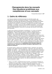
1. FUNCTIONING SCHEME OF DIRECT FIRED HEATERS
D
%
"
"
6
7
!
(
8
1
9
&
General functioning system
!
!
-
&
Detailed functioning system
5
'
::
!
;
)
!
..
'
- &
..
&!
'
!
)
&
..
&
-
'
'
.
.. -
)
)
:6
. !
:- &
)
&
!
&
)
2 &
.. '
.
-
'
/
3
'
'
-
'
-
'
:<:
!
'
!
4
/
'
-
)
&
-'
-'
)
-
.
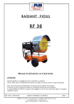
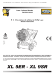
2. FUNCTIONING SCHEME OF INDIRECT AND POST-VENTILATED HEATERS
S
F2
T
C1
E
R
M
U
B
V
F1
A
EV
F4
F3
%
"
"
6
7
!
(
8
1
4
&
..
)
(6
General functioning system
!
!
-
- &
&!
&
'
!
..
)
'
)
=
'
-
'
)
)
Detailed functioning system
5
'
::
!
&
;
!
..
&
&
&
'
-
'
.
..
!
&
-
)
)
&
)
2 &
.. 5
:6
. -!
.
-
:- &
)
'
/
3
'
'
-
'
:<:
-'
)
/
!
'
)
!
'
-
)
!
'
&
3. INSTALLING THE UNIT
Safety precautions
'
'=
=
=
&=
=
6
'
'
.
Ventilation
requirements
!
)-
=
//
>2?5
' 3
!
'=
# &5
&5
+ &5
&5
$/&5
/ #/ @
/ /
/ +/
/ /
/$//
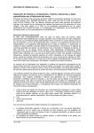
4. ROTARY COMPRESSOR
Exploded view
1
"
9
( )
&
A
B )
&
C
%
D
<
7
E
'
'
4
!
7
'
)
)
)
&
'
'
4.1
Assembling
sequence
"
!
'
4
'
.
!
'
2
'3 !
'
'
/
'
=
/#
&
-
/&
8
&
'
'
$//
'
'=
'
: :=
# / +
# / $/&5
F *
F
'
'
'
&
- '
:<:
/
'
-
4.2
Tuning
'
: :-
2
3
;
-
!
)
'
!
-
&
2
'
*
9
3-
/ /$
#
#
4.3
Cleaning the air
filter
!
#
%
$
#
"
"
$
"
$
!
' &
!
'
' &
'
&
"
4
=
//
#//
///
<
(
$ /
'
///
10
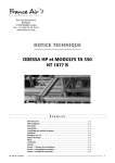
5. TROUBLESHOOTING
SWITCH ON
Check for correct voltage
rating (see data plate)
+/- 10% nom. value
Chech for the correct voltage
on the control panel
Check fuse (burn-outs,
damages,etc.)
THE UNIT DOES NOT
START
•
•
Check all connections
Replace with a new one with
identical ratings.
•
•
See charter 6.20
Replace the control unit
Check that the red lock-out
warning light is not alight
•
Switch on “O”, wait 10 seconds
and switch on “1”
Check that the overheat
thermostat has not been
activated
•
•
Leave the unit to cool
Position on “0” and then on”1”.
Check that the remote
thermostat is properly
connected and adjusted.
Only on AP and PV models
•
•
Check connections
Turn the thermostat tap
For operation without remote
thermostat, check that the
thermostat socket cover is
correctly inserted in the socket.
Only on AP and PV models
•
•
Check the metal jumper
Reinsert and block
•
Replace if not functioning
correctly
Check the burner control unit
Check that following parts are
working:
- Motor and capacitor
- Electrical cable and
plug
- Internal cables
11
•
•
Replace if not functioning
See chapter 6.16
•
•
Tighten the oil line fittings
Check for damages/craks in the
oil hoses
Check that the nozzle is clean
•
Check charter “ Cleaning the
combustion head”
Check that the combustion
head is clean
•
Clean the combustion head with
compressed air or a brush
dipped in oil
Check that the electrovalve
opens after the prepurge
sequence.
Only on AP and PV models
•
•
Check the electrical tester.
See chapter 6.13
Check for the presence of
external (spurious) lights
(sunlight, lamps)
•
Look for – and eliminate – light
reflectors due to sunrays, lamps,
etc. that could disturb the flame
sensor
Look for fires inside the
machine
Check the following parts are
working:
• Ignition transformer
• HT cables
• Ignition electrode
Check that the oil tank is full
Check for air bubbles in the
air filter
THE HEATER STARTS, THE
PREPURGE SEQUENCE
STARTS BUT THEN THE
HEATER STOPS WITHOUT
IGNITION
•
Check that oil flows to the
nozzle
12
•
•
Check the position of air and oil
hoses on the combustion head
Check that the o-ring on the
nozzle is not damaged
THE HEATER START,
IGNITES AND THEN STOPS
Check that the photocell is not
damaged, clean and fixed to
the combustion head
•
•
Clean the photocell with alcohol
Replace if necessary
Check that the nozzle is clean
•
•
See chapter 6.9
Replace oil nozzle
•
Wrong air pressure of the
compressor
Look for correct nozzle size on the
setting chart
Check the nozzle size
THE HEATER STARTS, THE
FLAME IGNITES BUT
COMBUSTION IS NOT
GOOD
Measure and regulate pressure
Check the nozzle is clean
•
•
See chaper6.9
Replace oil nozzle
Check that the oil filter is clean
•
See chapter 6.7
Check that there are no air
bubbles in the fuel line
•
•
Tighten fittings
Replace the faulty pipes/hoses
Wrong air pressure of the
compressor
•
Measure and regulate pressure
Oil is not correct, dirty,
polluted or contains water
•
Empty tank and refill with
correct fuel
Pulsating combustion
•
•
•
13
Check and clean oil nozzle
Check if o-ring on nozzle is
damaged
Check that the nozzle holder is
not damaged
Photocell activated
•
•
Dirty photocell: clean with
alcohol
No flame caused by:
• Dirty nozzle
• No oil
THE HEATER STOPS
SUDDENLY
Overheat
thermostatincorrectly
activated
•
•
Wrong location of overheat
thermostat (after incorrect
servicing, repairs, etc.)
Damaged electrical connection
cable
OK
Excessive overheating of
combustion chamber (overheat
thermostat activated)
•
•
•
•
•
•
•
•
14
Wrong nozzle (too large) (see
specification chart)
Wrong fuel pressure (too high)
– see specification chart
Insufficient ventilation due to
motor fault
Insufficient ventilation due to
fan failure
Blockage of airways due to dirt
or foreign objects
Exhaust pipe partially
obstructed
Combustion chamber clogged
by soot (see charter 3.10)
Room temperature too high
6. MAINTENANCE AND SERVICE
OPERATIONS
&'
'*
(
'
'
+'
& *(
'
+)' *
',
,-0
&
&'
','
*
*
/
'1
,*'
' (('
' *) ' )
)'
*
, ( * +'
. ,/'
( ),
'
, * /' ,
*1
6.1 CHECKING THE SUPPLY VOLTAGE
!
'
2 /63 !
/6
/6
'
• %
&
'
=
• "
&
• "
&
D
'
23
&
=<
>
-
'
.
6.2 CHECKING AND REPLACING THE
POWER CORD
• "
&
• 8
'
)
'
• 8
!
• <
'
=
B/* D
'
• 9
-
•
•
)
'
)
'
)
'
2
'
=#
•
)
• "
• " &
•
)3
6.3 CHECKING AND REPLACING THE
MOTOR
• ()
• " &
• "
&
-
!
• 8
• 9
•
• 8
&-
'
&
=
'
$ %#
'
•
)
&
• "
•
•
• 9
• 8
!
• 8
'
&
'
16
'
&
=
'
&
"
'
)
•
• ()
• 9
•
'
• "
-
&
6.4 CHECKING AND REPLACING THE
FAN
• "
&
&
&
!
• 8
•
• "
'
=
'
)
'
&
'
'
•
• "
&
)
•
)
6.5 EXHAUST GAS ANALYSIS (only for
indirect heaters)
7
1
• 8
)
4
&
'
*
17
)
• 5
34
/
( '* '5
2( )
'
&
&
,-3'
• ()
2
'
&
!
)
9
/
4
1
F
'
&
&
"
&
>'
&
&
-
F
)
2
'
3
&
=
"
2
)
&
2
3
'
<
9
G
)
)
$ *-$ +-$ ,3
.. 2
C &
-
6.7 CHECKING AND REPLACING THE
FUEL FILTER
'
'
6.6 CLEANING THE TANK
!
• C
• 7
• 8
&=
'
'
'
&
&
• 8
18
'
• "
&
-
!
• 9
=
•
6.8 CHECKING AND REPLACING THE
FUEL HOSE
"
&
!
&
"
&
'
• ()
'
&'
'
&
'
• 8
• "
6.9
CHECKING
REPLACING
CLEANING THE NOZZLE
..
..
AND
•
•
•
2
• "
•
•
.. <
3
&
<
'
..
( 6
%
$
19
..
#
%
•
•
3
7
'
)
6.10 CHECKING AND CLEANING THE
COMPRESSOR
!
"
=
'
•
•
•
'
=
//
#//
///
%
%
•
•
()
•
'
20
()
'
"
&
'
&
•
)
'
%
'
'
6.11 REPLACING AND ADJUSTING THE
AIR COMPRESSOR
!
'
•
•
•
()
'
%#
'
•
'
%#
•
'
'
' %
•
'
!
•
•
=
0
)
7
'
/ /#
H
2
3
#
"
! ""
%
$
"
#
%
" #
# 6 %
•
21
)
)
%#
'
•
FIX IN THE
CORRECT
POSITION!
•
•
•
•
)
'
)
8
•
•
%#
8
"
%
"
•
'
2
=/ /$
3
9
0
•
"
•
<
>
&
'
&
)
>
'
&
4
6.12
CHECKING
ADJUSTING VALVE
!
8
.
&
'
0
7
'
•
•
&
4'
'
22
•
•
•
•
0
4 '
D
4
1
THE
=
PRESSURE
•
•
=
"
"
&
!
• 9
>
•
•
9
'
)
•
6.13 CHECKING AND REPLACING THE
AIR SOLENOID VALVE (only for indirect
and post-ventilation models)
•
=
! !
$
4'
2
&
-2/ 3
6.14
CHECKING,
CLEANING
CONTROLLO,
ADJUSTING
AND
REPLACING
IGNITION
ELECTRODES
• ()
•
&
'
" &
93:
•
-
'
•
6
$
'
3
"
'
'
"
'
• "
23
&
•
'
• "
&
'
'
•
..
0
'
•
•
•
!
&
•
)
• 9
&
6.15 CHECKING AND REPLACING HIGH
VOLTAGE IGNITON CABLES
=
• "
• "
• 9
• 4'
• 6
&
&
)
'
&
&
• "
'
&
%
','
%
6=1/ $
! %
•
•
!
, *&
;
% # $
$
'
"$
3<
%
%
• 9
• 8
"
• 9
• 9
2
'
8
#
6.16 CHECKING AND REPLACING THE
IGNITION TRANSFORMER
)
'
%
#
% 1
8
"
#
'
24
•
• ()
-
'
"
6.17 REPLACING THE FUSE
• <
• ()
H
&
"
• "
•
'=
&
'
• 4
• ()
• H
6.18
CHECKING,
CLEANING
REPLACING THE FLAME SENSOR
• ()
-
AND
!
• 9
I
&
•
•
25
=
'
&
'
-
6.19 CHECKING AND REPLACING THE
SAFETY THERMOSTAT
•
• "
!
• 9
•
•
&
% &
'
6.20 CHECKING AND REPLACING THE
FLAME CONTROL UNIT
)
=
!
&
-
'
"
8
!
4
=
'
>
2
"
=
3
&
'
&
3
'
"
!
'
-
-
'
)
'
=
'
'
7 '
7
J
'
'
!
4
'
!
2
>
2
"
!
2)
& 3
2) '
-
&
3
4
'
'
&
'
26
&
3
'
' 2'
"
&
'
-
3
9
2
!
C &
• !
•
'
9
'
'2
-
& '
#/3
'
6.21 BURNER HEAD (OLD TYPE)
!
'
'
..
'
•
!
&
9
9
=
27
<
..
'
&
&
..
'
-
<
•
•
•
•
..
K
K
K
K
'
'
'
'
2
L
M
&
&
'
.. 3-
..
28
7. SETTING CHARTS
Indirect fired heaters
+
'
&'
,
;
=
( ) '**
* >'
#
NF /
O
3? )
=
LCM
&
7? )
/
=
<4 )
&
#
NF #
) '**
/ ',
>>,'
* /' &' ( *
/ *'
/ /P/
9(C 6 D
/ /A7B
/$/,
$#O"
! &
/ P/
9(C 6 D
/*# A7B
/$/,+
$#O"
#
! &
/ P/
9(C 6 D
//A7B
/$/,
$#O"
#
! &
*
O
#
NF #
+O
'
#
Direct fired heaters
+
'
&'
,
3?
/
( ) '**
* >'
D
#
N F ,/
#O
D
#
N F ,/
O
! &
#
NF /
O
! &
=
74
;
! &
) '**
'
/ ',
>>,'
* /' &' ( *
/ *'
/ + P/ /
9(C 6 D
/ /A7B
/$/,
>>
#
*
/ + P/ ,
9(C 6 D
/$# A7B
/$/,*
$#O"
#
*
/ /P/
9(C 6 D
/*# A7B
/$/,+
$#O"
#
/ P/
9(C 6 D
//A7B
/$/,
$#O"
*
A1
=
D
7@
A1
=
<4
D
#
NF #
+O
! &
A1
30
#
Direct fired heaters with post-ventilation
+
'
&'
,
;
=
( ) '**
* >'
#
NF #
>>
<4)=
/
) '**
! &
/ P/
9(C 6 D
//A7B
/$/,
! &
/ P/ #
9(C 6 D
#/A7B
/$/, ,
O
=
LCM
A4)=
-
&
N F #/
O
'
/ ',
>>,'
31
* /' &' ( *
/ *'
$#O"
#
$#O"
#
8. WIRING DIAGRAMS
Direct fired heaters
"
4
D
%
'
!
!4
"
32
Indirect fired heaters and direct fired heaters with postventilation
"
4
D
%
(6
'
!
!4
"
!B
33