1
Tachometer
Installation and Operation Instructions
Siemens VDO
Allentown, Pennsylvania USA
THE INSTRUCTIONS FOR INSTALLATION AND ELECTRICAL WIRING FOR THESE TACHOMETERS FOLLOW. USE IS RESTRICTED TO 12 VOLT NEGATIVE GROUND ELECTRICAL SYSTEMS.
Tachometer Installation
Parts List
Item
1.
2.
3.
Description
Quantity
Tachometer
Decals, 2 x 4 (not contingency decals)
Posi-Lock Connectors
1
2
3
Installing the tachometer is a three-step process.
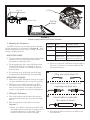
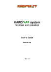
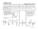
1. Cylinder Selection
Your PRT Tachometer is factory set for an eight cylinder
engine. For other applications the selector switches must be
set according to Diagram A.
Optional Items Which May Be Needed:
Flush In-Dash Mounting Bracket #240 104
On-Dash Mounting Bracket
#240 103
CAUTION: Read these instructions thoroughly before making installation. Always wear safety glasses, and always disconnect the battery ground before making any electrical connections. If in doubt,
please contact your dealer or VDO Instruments at 1-800-265-1818.
%
·
Remove the 4 cap nuts, lockwashers and rear cover.
·
Find your application in Diagram A and set the
switches accordingly.
·
Replace the rear cover, lockwashers and cap nuts.
DO NOT OVERTIGHTEN!
$ BUQb3_fUb
#"%
'%
!&#
((
%'%
3Q`>ed
%
$'%
#!(
=_TU
CgYdSX
BUcUd2edd_^
CU\USd_bCgYdSX
1
2
1
2
Di`U!)$2e\R
DQSX_]UdUb2QS[
bUQbSQ^bU]_fUT
·VRQ
F\OLQGHU
RQ
F\OLQGHU
RQ
F\OLQGHU
·VRQ
F\OLQGHU
Diagram A
Dimensions and Selector Switch Settings
P/N 0 515 010 561
Rev. 07/03
&ROXPQ0RXQW
2Q'DVK
9^4QcX
8QGHU'DVK
5ROO%DU
0RXQW
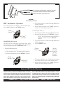
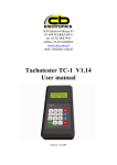
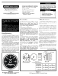
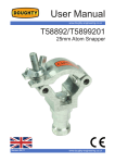
Diagram B
Possible mounting locations for the Extreme Tachometer
2. Mounting the Tachometer
Your PRT tachometer can be mounted almost anywhere.
Several suggestions are illustrated in Diagram B. Some
installation techniques may require optional accessories,
cutting, or drilling new holes.
MOUNTING NOTES:
·
The most common mounting location is on the steering
column or roll cage using a band clamp and the
included short mounting bracket.
·
For mounting in the dash, optional flush mounting
bracket [P/N 240 104] is recommended. The rear
cover may also be used as a mounting clamp for in
dash mounting.
·
For mounting on top of the dash, optional longer
mounting bracket [P/N 240 103] is recommended.
IGNITION
TYPE
CONNECTIONS
Standard
points / breakerless
negative terminal on coil
CD
points
points connection to CD box
breakerless
positive terminal on coil
MSD, ACCEL,
MALLORY, DDIS
(distributorless),etc.
Tach output terminal on ignition
box, or points connection to
ignition box, or negative coil
Electronic
·
¯
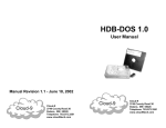
Be sure to connect the tachometer using the supplied
Posi-Lock Connectors. Use them as shown in the
following illustration:
CdbY`gYbUU^TcQR_ed
MOUNTING CAUTIONS:
·
Make sure your PRT Tachometer does not rest against
any glass, windshield A pillars, or any roll cage tubes.
·
VDO does not recommend mounting your PRT
Tachometer close to other electrical components or
their associated wiring. For example, the ignition
system box, the ignition coil, electric fuel pump, etc.
° 9^cUbdUQSXgYbUY^d_Q]Q\UU^T
Uh`_cY^W_^\iRQbUgYbU
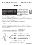
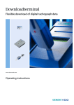
3. Wiring the Tachometer
·
Turn off the ignition and disconnect the negative
terminal from the battery post if you havent already
done so.
·
Wire the tachometer to the vehicle as shown in
Diagram C *.
* Refer to your vehicles owner/service manual or the
aftermarket ignition manufacturers instructions for
a recommended place to tap the signal. Typical
examples are shown in the table to the right.
±
·
8Q^TdYWXdU^]Q\UU^Tc
Y^d_U^Tc_VRQbbU\
Reconnect the battery and start your vehicle to test
the installation.
5('
YROWSRZHUDQGLOOXPLQDWLRQFRQQHFWWRIXVHSDQHO
%/$&.
7DFKJURXQGFRQQHFWWRFRPPRQFKDVVLVJURXQG
*5((1
,JQLWLRQ7DFKRPHWHUVLJQDOFRQQHFWLRQ
Diagram C
General Wiring Information
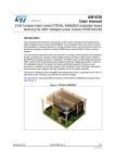
PRT Tachometer Operation
·
For normal operation and display of current engine speed,
rotate the Mode Switch to the TACH position.
The pointer will move to indicate the high RPM stored
by the tachometer.
·
Rotate the Mode Switch to the TACH position to
return to normal tachometer operation.
=_TU
CgYdSX
2. Resetting the memory.
·
Turn the ignition ON. The engine MAY be running.
·
Rotate the Mode Switch to the RECALL position.
NOTE: The PRT memory cannot be RESET if
the Mode Switch is not in the RECALL
position.
High RPM Recall Operation
·
The PRT will store and display the highest engine speed
achieved during a race. The high RPM recall is displayed by
the tachometer pointer when in RECALL mode.
The pointer will move to indicate the high RPM stored
by the tachometer.
·
Press the RESET button.
²DQSX³
@_cYdY_^
BUcUd
2edd_^
1. Display high RPM memory.
·
Turn the igniton ON. The engine MAY be running.
·
Rotate the Mode Switch to the RECALL position.
=_TU
CgYdSX
²BUSQ\\³
@_cYdY_^
=_TU
CgYdSX
=ecd2U
Y^dXU
²BUSQ\\³
@_cYdY_^
·
The pointer will drop to zero. (If the engine is running,
the pointer will drop to the current engine speed.)
·
Rotate the Mode Switch to the TACH position to
return to normal tachometer operation.
Siemens VDO Limited Warranty
VDO North America, LLC. warrants all merchandise against defects in factory workmanship and materials for a period of 24 months after purchase. This warranty
applies to the first retail purchaser and covers only those products exposed to
normal use or service. Provisions of this warranty shall not apply to a VDO product
used for a purpose for which it is not designed, or which has been altered in any
way that would be detrimental to the performance or life of the product, or misapplication, misuse, negligence or accident. On any part or product found to be
defective after examination by VDO North America, VDO North America will only
repair or replace the merchandise through the original selling dealer or on a direct
basis. VDO North America assumes no responsibility for diagnosis, removal and/
or installation labor, loss of vehicle use, loss of time, inconvenience or any other
consequential expenses. The warranties herin are in lieu of any other expressed or
implied warranties, including any implied warranty of merchantability or fitness,
and any other obligation on the part of VDO North America, or selling dealer.
(NOTE: This is a Limited Warranty as defined by the Magnuson-Moss Warranty Act of 1975.)
Siemens VDO . http://sso-usa.siemensvdo.com/ . Phone: 1-800-265-1818