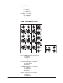
1
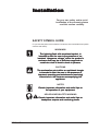
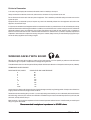
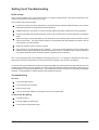
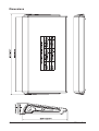
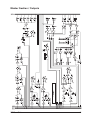
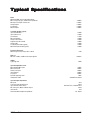
GB2 User
Guide
GB2 User Guide
1
IMPORTANT
Please read this manual carefully before using
your mixer for the first time.
© Harman International Industries Ltd. 2006
All rights reserved
Parts of the design of this product may be protected by worldwide patents.
Part No. ZM0344-01
Soundcraft is a trading division of Harman International Industries Ltd. Information in this manual
is subject to change without notice and does not represent a commitment on the part of the
vendor. Soundcraft shall not be liable for any loss or damage whatsoever arising from the use of
information or any error contained in this manual.
No part of this manual may be reproduced, stored in a retrieval system, or transmitted, in any
form or by any means, electronic, electrical, mechanical, optical, chemical, including photocopying
and recording, for any purpose without the express written permission of Soundcraft.
Harman International Industries Limited
Cranborne House
Cranborne Road
POTTERS BAR
Hertfordshire
EN6 3JN
UK
Tel:
+44 (0)1707 665000
Fax: +44 (0)1707 660742
http://www.soundcraft.com
2
GB2 User Guide
Contents
Introduction
Key Features
Warranty
5
6
7
Installation
9
SAFETY SYMBOL GUIDE
IMPORTANT SAFETY WARNINGS
Mains Installation
WORKING SAFELY WITH SOUND
Setting Up & Troubleshooting
Optional External Power Supply
Audio Connector Pinouts
Dimensions
9
10
12
14
14
16
17
18
Block Diagrams
19
Input Channels
Master Section / Outputs
20
21
Using The Console
23
Mono Input
Stereo Input
Master Section
Rear Connector Panel
Lamps
24
26
29
31
32
Typical Specifications
33
Mark Up Sheets
34
GB2 User Guide
3
NOTE: This equipment has been tested and found to comply with the limits for a Class A digital
device, pursuant to Part 15 of the FCC Rules. These limits are designed to provide reasonable
protection against harmful interference when the equipmentis operated in a commercial
environment. This equipment generates, uses and can radiate radio frequency energy and, if
not installed and used in accordance with the instruction manual, may cause harmful interference
to radio communications. Operation of this equipment in a residential area is likely to cause
harmful interference in which case the user will be required to correct the interference at his own
expense.
This Class A digital apparatus meets the requirements of the Canadian Interference-Causing
Equipment Regulations.
Cet appareil numérique de la Classe A respecte toutes les exigences du Règlement sur le
matériel brouilleur du Canada.
4
GB2 User Guide
Intr
oduction
Introduction
GB2 User Guide
5
Key Features
Thank you for buying the GB2 mixing console. its main features are:
Individually switched 48V phantom power on every mono input module.
6 Aux sends.
4 Group sends (paired).
6 X 2 Output Matrix.
New GB30 mic pre-amp.
4-band GB30 EQ.
Integral power supply, with an external power supply link option.
All metal TRS jacks and Neutrik XLRs.
Direct outputs on all mono input channels.
6
GB2 User Guide
Warranty
1
2
3
4
5
6.
7.
GB2 User Guide
Soundcraft is a trading division of Harman International Industries Ltd.
End User means the person who first puts the equipment into regular operation.
Dealer means the person other than Soundcraft (if any) from whom the End User
purchased the Equipment, provided such a person is authorised for this purpose by
Soundcraft or its accredited Distributor.
Equipment means the equipment supplied with this manual.
If within the period of twelve months from the date of delivery of the Equipment to
the End User it shall prove defective by reason only of faulty materials and/or
workmanship to such an extent that the effectiveness and/or usability thereof is
materially affected the Equipment or the defective component should be returned to
the Dealer or to Soundcraft and subject to the following conditions the Dealer or
Soundcraft will repair or replace the defective components. Any components
replaced will become the property of Soundcraft.
Any Equipment or component returned will be at the risk of the End User whilst in
transit (both to and from the Dealer or Soundcraft) and postage must be prepaid.
This warranty shall only be available if:
a) the Equipment has been properly installed in accordance with instructions
contained in Soundcraft's manual; and
b) the End User has notified Soundcraft or the Dealer within 14 days of the defect
appearing; and
c) no persons other than authorised representatives of Soundcraft or the Dealer
have effected any replacement of parts maintenance adjustments or repairs to the
Equipment; and
d) the End User has used the Equipment only for such purposes as Soundcraft
recommends, with only such operating supplies as meet Soundcraft's specifications
and otherwise in all respects in accordance Soundcraft's recommendations.
Defects arising as a result of the following are not covered by this Warranty: faulty or
negligent handling, chemical or electro-chemical or electrical influences, accidental
damage, Acts of God, neglect, deficiency in electrical power, air-conditioning or
humidity control.
The benefit of this Warranty may not be assigned by the End User.
End Users who are consumers should note their rights under this Warranty are in
addition to and do not affect any other rights to which they may be entitled against
the seller of the Equipment.
7
8
GB2 User Guide
Installa
tion
Installation
For your own safety and to avoid
invalidation of the warranty please
read this section carefully.
SAFETY SYMBOL GUIDE
For your own safety and to avoid invalidation of the warranty all text marked with these symbols
should be read carefully.
WARNINGS
The lightning flash with arr
arrowhead
owhead symbol, is
esence of unalertt the user to the pr
presence
intended to aler
ous voltage” within the pr
oduct’s
insulated “danger
product’s
“dangerous
enclosur
e that may be of suf
ficient magnitude to
sufficient
enclosure
constitute a risk of electric shock to persons.
CAUTIONS
The exclamation point within an equilateral triangle
is intended to aler
esence of
alertt the user to the pr
presence
impor
tant operating and maintenance (servicing)
important
instructions in the literatur
e accompanying the
literature
appliance.
NOTES
Contain impor
tant infor
mation and useful tips on
important
information
the operation of your equipment.
HEADPHONES SAFETY WARNING
Contain impor
tant infor
mation and useful tips on
important
information
headphone outputs and monitoring levels.
GB2 User Guide
9
IMPORTANT SAFETY WARNINGS
THIS UNIT MUST BE EARTHED
Under no circumstances should the mains earth be disconnected from
the mains lead.
The wires in the mains lead are coloured in accordance with the following code:
Earth:
Green and Yellow (Green/Yellow - US)
Neutral:
Blue (White - US)
Live:
Brown (Black - US)
As the colours of the wires in the mains lead may not correspond with the coloured markings identifying the terminals in your plug,
proceed as follows:
The wire which is coloured Green and Yellow must be connected to the terminal in the plug which is marked with
the letter E or by the earth symbol.
The wire which is coloured Blue must be connected to the terminal in the plug which is marked with the letter N.
The wire which is coloured Brown must be connected to the terminal in the plug which is marked with the letter L.
Ensure that these colour codings are followed carefully in the event of the plug being changed.
To avoid the risk of fire, replace the mains fuse only with the correct
value fuse, as marked on the rear panel.
The internal power supply unit contains no user serviceable parts. Refer
all servicing to a qualified service engineer, through the appropriate
Soundcraft dealer.
10
GB2 User Guide
WARNINGS
• Read these instructions.
• Keep these instructions.
• Heed all warnings.
• Follow all instructions.
• This unit contains no user serviceable parts. Refer all servicing to a qualified service engineer,
through the appropriate Soundcraft dealer.
• Clean the apparatus only with a dry cloth.
• Do not install near any heat sources such as radiators, heat resistors, stoves, or other apparatus
(including amplifiers) that produce heat.
• Do not block any ventilation openings. Ventilation should not be impeded by covering the
ventilation openings with items such as newspapers, table cloths, curtains etc. Install in
accordance with the manufacturer’s instructions.
• Do not use this apparatus near water. The apparatus must not be exposed to dripping or
splashing. Objects containing liquid must not be placed on the apparatus.
• The disconnect device is the mains plug; it must remain accessible so as to be readily operable
in use.
• Do not defeat the safety purpose of the polarized or grounding type plug. A polarized plug has
two blades with one wider than the other. A grounding type plug has two blades and a
third grounding prong. The wide blade or the third prong are provided for your safety.
When the provided plug does not fit into your outlet, consult an electrician for replacement
of the obsolete outlet.
• Protect the power cord from being walked on or pinched particularly at plugs, convenience
receptacles and the point where they exit from the apparatus.
• Only use cables and hardware specified by the manufacturer.
• Unplug this apparatus during lightning storms or when unused for long periods of time.
• Refer all servicing to qualified service personnel. Servicing is required when the apparatus has
been damaged in any way such as power-supply cord or plug is damaged, liquid has
been spilled or objects have fallen into the apparatus, the apparatus has been exposed
to rain or moisture, does not operate normally or has been dropped.
• It is recommended that all maintenance and service on the product should be carried out by
Soundcraft or its authorised agents. Soundcraft cannot accept any liability whatsoever
for any loss or damage caused by service, maintenance or repair by unauthorised
personnel.
• If a trolley is used to carry this apparatus, use caution when moving the trolley / apparatus
combination to avoid injury from tip-over.
• No naked flame sources, such as lighted candles or cigarettes etc., should be placed on the
apparatus.
• Warning: To reduce the risk of fire or electric shock, do not expose this apparatus to rain or
moisture. Do not expose the apparatus to dripping or splashing and do not place objects
filled with liquids, such as vases, on the apparatus.
GB2 User Guide
11
General Precautions
Avoid storing or using the mixing console in conditions of excessive heat or cold, or in positions where it is likely to be subject to
vibration, dust or moisture. Do not use any liquids to clean the fascia of the unit: a soft dry cloth is ideal.
Avoid using the console close to strong sources of electromagnetic radiation (e.g. video monitors, high-power electric cabling): this
may cause degradation of the audio quality due to induced voltages in connecting leads and chassis.
Caution! In all cases, refer servicing to qualified personnel.
Handling and Transport
The console is supplied in a strong carton. If it is necessary to move it any distance after installation it is recommended that this
packing is used to protect it. Be sure to disconnect all cabling before moving. If the console is to be regularly moved we recommend
that it is installed in a foam lined flightcase. At all times avoid applying excessive force to any knobs, switches or connectors.
Power Cable
Always use the power supply cable supplied with the mixer: the use of alternative cables may cause damage and voids the warranty.
W a r n i n g ! In the event of an electrical storm, or large mains voltage
fluctuations, immediately switch off the mixer and unplug from the mains.
Signal Levels
It is important to supply the correct input levels to the console, otherwise signal to noise ratio or distortion performance may be
degraded; and in extreme cases, damage to the internal) circuitry may result. Likewise, on all balanced inputs avoid sources with
large common mode DC, AC or RF voltages, as these will reduce the available signal range on the inputs. Note that OdBu =0.775V
RMS.
Refer to the Specifications section for details of input and output levels.
Mains Installation
General Wiring Procedures
To take full advantage of the excellent signal to noise ratio and low distortion of Soundcraft consoles, care must be taken to ensure
that incorrect installation and wiring does not degrade the performance of the desk. Hum, buzz, instability and Radio Frequency
interference can usually be traced to earth loops and inferior earthing systems. In some areas, especially heavily industrial areas,
the incoming mains earth will not be adequate and a separate technical earth for all the audio equipment must be supplied. However,
check with your local electricity supply company to ensure that safety regulations are not infringed or negated.
The successful, hum free, installation of a system requires forethought, and the establishment of a set of ground rules, which must
be consistently adhered to at all stages of installation.
12
GB2 User Guide
Initial Wiring Considerations
For optimum performance, it is essential for the earthing system to be clean and noise free, as all signals are referenced to this
earth. A central point should be decided on for the main earth point system, and all earths should be 'star fed' from this point. It is
common electrical practice to `daisy chain' the earths to all electrical outlets but this method is unsuitable for audio installations. The
preferred method is to run an individual earth wire from each outlet, back to the system star point to provide a safety earth screen
reference for each piece of equipment.A separate earth wire should also be run from each equipment rack and area, to the star
point. This may or may not be used depending on circumstances, but it is easier to install in the first place, than later when problems
arise.The location of the star point should be a convenient, easily accessible place, preferably at the rear of the console or in the
main equipment rack.
Install separate 'clean' and 'dirty' mains outlets, wired individually back to the incoming mains distribution box. Use the 'clean' supply
for all audio equipment and the `dirty' supply for all lighting, etc. Never mix the two systems.
If necessary, to provide sufficient isolation from mains borne interference, install an isolating transformer. This should be provided
with a Faraday Shield which must be connected with earth.
Never locate the incoming mains distribution box near audio equipment, especially tape recorders, which are very sensitive to
electro-magnetic fields.
Ensure that all equipment racks are connected to earth, via a separate wire back to the star point.
Equipment which has unbalanced inputs and outputs may need to be isolated from the rack to prevent earth loops.
Audio Wiring
Having provided all equipment with power and earthing connections, consideration must be given to the method of providing audio
interconnection and adequate screening of those interconnections. This must be done in a logical sequence to avoid problems and
assist in the localisation of problem equipment.
Connect the FOH or Monitor system to the console and check for any hum, buzz, or RFI. Only when you are satisfied with the
quietness of the console and the PA system should you proceed with the next step.
Connect stereo or multitracktape recorders, FX and foldback sends one at a time, checking and isolating any connection which
degrades performance.
Connect all other peripheral devices.
Connect all microphone lines.
By following this sequence much time and future trouble will be saved, and the result will be a quiet, stable system.
Shielding
Audio equipment is supplied with a variety of input and output configurations, which must be taken into consideration when deciding
where the screen connections should be made. There are three sources of unwanted signal being impressed on the screen, which
are as follows:
Extraneous electrostatic or electromagnetic fields.
Noise and interference on the earth line.
Capacitive coupling between the screen and signal wires.
To minimise the adverse affects of the unwanted coupling to the signal wires, it is important that the screen is connected at one end
only, i.e. the screen must not carry any signal) current. Any signal) on the wires within the screen will be capacitively coupled to the
screen. This current will ultimately be returned to the source of the signal, either directly, if the screen is connected at the signal
source end, or indirectly via the earthing system, if the signal is connected at the signal destination end. The indirect connection will
cause an increase in high frequency cross-talk, and should be avoided wherever possible.
Therefore, in general, always connect the shield only at the signal source end. In high RF areas, the screen can also be connected
to earth via a 0.01 mF capacitor. This will present a short circuit at RF frequencies, thus lowering the effective shield impedance to
ground. However, at low audio frequencies the reactance of the capacitor will be sufficiently high not to cause an earth loop problem.
GB2 User Guide
13
Points to Remember
In all cases, use good quality twin screened audio cable. Check for instability at the output.
Always connect both conductors at both ends, and ensure that the screen is only connected at one end.
Do not disconnect the mains earth from each piece of equipment. This is needed to provide both safety and screen returns to the
system star point.
Equipment which has balanced inputs and outputs may need to be electrically isolated from the equipment rack and/or other
equipment, to avoid earth loops.
It is important to remember that all equipment which is connected to the mains is a potential source of hum and interference and may
radiate both electrostatic or electromagnetic radiation. In addition, the mains will also act as a carrier for many forms of RF interference
generated by electric motors, air-conditioning units, thyristor light dimmers etc. Unless the earth system is clean, all attempts to
improve hum noise levels will be futile. In extreme cases there will be no alternative but to provide a completely separate and
independent `technical earth' to replace the incoming 'noisy earth'. However, always consult your local electricity supply authority to
ensure that safety regulations are not being infringed.
WORKING SAFELY WITH SOUND
Although your new console will not make any noise until you feed it signals, it has the capability to produce sounds which when
monitored through an amplifier or headphones can damage hearing over time.
The table below is taken from the Occupational Safety & Health Administration directive on Occupational noise exposure (1926.52):
PERMISSABLE NOISE EXPOSURE
DURATION PER DAY, HOURS
8
6
4
3
2
1.5
1
0.5
<0.25
SOUND LEVEL dBA SLOW RESPONSE
90
92
95
97
100
102
105
110
115
Conforming to this directive will minimise the risk of hearing damage caused by long listening periods. A simple rule to follow is the
longer you listen the lower the average volume should be.
Please take care when working with your audio - if you are manipulating controls which you don’t understand (which we all do when
we are learning), make sure your monitors are turned down. Remember that your ears are the most important tool of your trade, look
after them, and they will look after you.
Most importantly - don’t be afraid to experiment to find out how each parameter affects the sound - this will extend your creativity and
help you to get the best results.
Recommended headphone impedance is 50-600 ohms.
14
GB2 User Guide
Setting Up & Troubleshooting
Initial set-up
Once you have connected up your system (see the sections on connection and wiring earlier in this manual for guidance) you are
ready to set initial positions for the controls on your mixer.
Set up individual input channel as follows:
Connect your sources (microphone, keyboard etc.) to the required inputs and release the MUTE switches. Note: Phantom
powered mics should be connected before the 48V is switched on.
Set Master faders at 0, input faders at 0, route the channels to MIX and set power amplifier level to suit the application.
Provide a typical performance level signal and press the PFL button on the first channel, monitoring the level on the bargraph
meters.
Adjust the input gain until the meter display is in the amber section, with occasional peaks to the first red LED at a typical
maximum source level. This allows sufficient headroom to accommodate peaks and establishes the maximum level for
normal operation (but see note below).
Repeat this procedure on other channels as required.
Listen carefully for the characteristic sound of `feedback’. If you cannot achieve satisfactory input level setting without
feedback, check microphone and speaker placement and repeat the exercise. If feedback persists, it may be necessary to
use a Graphic Equaliser to reduce the system response at particular resonant frequencies.
Note: The initial settings should only be regarded as a starting point for your mix. It is important to remember that many factors
affect the sound during a live performance, for instance the channel EQ settings or even the size of the audience!
You are now ready to start building the mix and this should be done progressively, listening carefully for each component in the mix
and watching the meters for any hint of overload. If this occurs, back off the appropriate Channel Fader slightly until the level is out
of the red segments, or adjust the Mix Master Faders. This procedure will ensure that the mixer is set up correctly, with adequate
headroom. If more amplification is needed, adjust the power amplifier level controls.
Troubleshooting
No Power
Is the mains supply present?
Is the mains lead firmly connected?
Check the mains fusing
If only one of the power indicators is illuminated, consult your Soundcraft dealer
Condenser Mic Not Working
Is the 48V turned on?
Is the mic plugged into the Mic input?
Is the mic cable a balanced 3-wire type?
GB2 User Guide
15
Meters not showing any signal
Has the input gain been set correctly? (see above.)
Is the source connected to the appropriate input socket for the level of signal?
Do you have something connecetd on the Inserts, and is that external device switched on?
Are the Master faders set at max., are input faders set high enough and is the channel routed to the output being monitored?
Is the MUTE switch released on the relevant channels?
Is the appropriate monitor select switch pressed?
Is there a PFL/AFL pressed on another channel?
No Mix output
Check that the Mix Master Fader is up?
No Monitor output
Are the Monitor + Phones controls set high enough?
Is the appropriate monitor select switch pressed?
Headphones Distorting
Are the headphones less than 50Ω impedance?
Is the Phones level set too high?
Optional External Power Supply
Although the GB2 has its own internal power supply, an external backup power supply (DPS-3) can be connected to provide a
backup power supply. There is a dedicated connector on the rear connector panel.
16
GB2 User Guide
Audio Connector Pinouts
GB2 User Guide
17
Dimensions
18
GB2 User Guide
Bloc
k Dia
grams
Block
Diag
GB2 User Guide
19
Input Channels
20
GB2 User Guide
Master Section / Outputs
GB2 User Guide
21
22
GB2 User Guide
Using The Console
GB2 User Guide
23
Mono Input
The MIC GAIN control (1) adjusts the sensitivity of both mic (XLR) and Line (1/4” jack) inputs.
Both inputs are electronically balanced, and are located on the rear connector panel.
The PEAK LED (2) monitors two points in the audio path: pre-insert point and post-EQ.
The 48V switch (3) applies 48V phantom power to the input XLR. An adjacent LED
indicates when the phantom power is on.
Don’t connect microphones with the phantom power switched on. Only switch the
phantom power on or off with the output fader down.
The PHASE switch (4) reverses the phase of the input.
The HI-PASS switch (5) enables the high-pass filter.
The module insert point is pre-EQ , pre-fader. It is located on the rear connector panel.
The EQ section (6) is four band, with shelving HF and LF, and swept peaking high and low mid
sections.
The HF and LF sections give +/-15dB cut/boost at 12kHz and 60Hz respectively. The Lo-mid
section gives +/-15dB cut/boost at 80Hz-1.9kHz. The Hi-mid section gives +/-15dB cut/boost at
550Hz-13kHz.
The section is switched in by the EQ switch (7).
The signal in the module is turned on and off by the MUTE switch (8). An adjacent LED illuminates
when the module is muted. All outputs from the module are muted, except for the Direct Output
if its Pre button is depressed. The PFL will still work whilst the module is muted.
Signal is sent to the AUX 1-6 busses via individual level pots (9). Aux 1 and 2 are both post-eq*
pre-fade feeds. Aux 3 and 4 are jointly selectable, via the PRE switch (10) to be pre-fade* or
post-fade feeds. Aux 5 and 6 are post-fade feeds*.
* Note: there is a dealer-implemented option to connect aux 1 and 2 feeds as pre-eq
pre fade. This would also affect aux 3 and 4 when they are selected as pre-fade.
Aux 5 and 6 may be connected to follow aux3/aux4 pre/post routing.
The warranty is voided if these options are implemented by anyone other than an
Authorised Soundcraft Dealer.
Post-fader signal level is controlled by a 100mm fader (11).
Signal for the mix and group busses are routed via the PAN pot (12). The pan pot positions the
signal within the stereo image.
The signal can be sent to the stereo mix busses (13), groups 1-2 (14) and groups 3-4 (15). Note
the use of groups 1 & 2, and groups 3 & 4 as 2 sets of stereo pairs.
A signal LED (16), next to the fader, meters the post-EQ, pre-mute signal.
The PFL switch (17) feeds the pre-mute signal to the monitor outputs and phones output. An
adjacent LED indicates when the PFL is on.
24
GB2 User Guide
Rear Connectors
INSERT (1/4" TRS Jack)
Tip
Send Signal
Ring Return Signal
Sleeve Ground
LINE INPUT (1/4" TRS Jack)
Tip
Signal Hot
Ring Signal Cold
Sleeve Ground
MIC INPUT (3 pin female XLR)
Pin 1 Ground
Pin 2 Signal Hot
Pin 3 Signal Cold
DIRECT OUTPUT (1/4" TRS Jack)“
Tip
Signal Hot
Ring Signal Cold
Sleeve Ground
The DIRECT OUTPUT is normally post fader. Pressing the PRE button switches it to pre-insertpoint.
GB2 User Guide
25
Stereo Input
MIC GAIN (1) adjusts the sensitivity of the stereo pair of mix XLR inputs. They are electronically
balanced, and are located on the rear connector panel.
The 48V switch (2) applies 48V phantom power to the input XLRs. An adjacent
LED indicates when the phantom power is on.
Don’t connect microphones with the phantom power switched on. Only switch the
phantom power on or off with the output fader down.
The PHASE switch (3) inverts the phase of the left channel XLR.
The LINE level control (4) adjusts the signal level from the stereo pair of line input 1/4” jacks on
the rear connector panel. The line inputs are balanced.
The LINE TO MIX/LINE TO CHAN (5) switch works as follows:
When the switch is in the raised position (LINE TO MIX) the signals from the line
inputs are routed (via the line level control) directly to the main mix l & r busses.
The XLR mic inputs are routed through the channel. This, in effect, gives an extra
stereo return input.
When the switch is in the depressed position (LINE TO CHAN) the signals from
the line inputs are routed through the channel. The mic XLR inputs are not used.
The L switch (6) routes the left input signal to both L and R channels in the module. The R switch
similarly routes the right input signal. Pressing L and R together mono sums the input.
The PEAK LED (7), monitors both left and right signals pre-EQ.
The EQ section (8) has four bands, with shelving high and low frequencies and peaking highmid and low-mid bands.
The HF control gives +/-15dB cut/boost at 12KHz. The LF control gives +/-15dB cut/boost at
60Hz. The HM control gives +/-15dB cut/boost at a centre frequency of 2.5kHz, and the LM
control gives +/-15dB cut/boost at a centre frequency of 450Hz.
The EQ is switched in by the EQ switch (9).
The stereo signal in the module is turned on and off by the MUTE switch (10). An adjacent LED
illuminates when the module is muted. The PFL will still work whilst the module is muted. The
Line To Mix routing [see (5) above] is not affected by the MUTE switch.
A mono sum of the signal is sent to the AUX 1-6 busses via individual level pots (11). Aux 1 and
2 are both post-eq* pre-fade feeds. Aux 3 and 4 are jointly selectable, via the PRE switch (12) to
be pre-fade* or post-fade feeds. Aux 5 and 6 are post-fade feeds*.
* Note: there is a dealer-implemented option to connect aux 1 and 2 feeds as pre-eq
pre fade. This would also affect aux 3 and 4 when they are selected as pre-fade.
Aux 5 and 6 may be connected to follow aux3/aux4 pre/post routing.
The warranty is voided if these options are implemented by anyone other than an
Authorised Soundcraft Dealer.
The BAL control (13) allows the stereo image to be balanced between the left and right channels
within the module.
Post-fader signal level is controlled by a 100mm stereo fader (14).
The signal can be sent to the stereo mix busses (15), groups 1-2 (16) and groups 3-4 (17). Note
the use of group 1 & 2, and group 3 & 4 as 2 sets of stereo pairs.
A signal LED (18), next to the fader, meters the post-EQ, pre-mute signal.
The PFL switch (19) feeds a mono sum of the pre-mute signal to the monitor output and phones
output. An adjacent LED indicates when the PFL is on.
26
GB2 User Guide
Rear Connectors
MIC INPUT LEFT and RIGHT (3 pin female XLR)
Pin 1 Ground
Pin 2 Signal Hot
Pin 3 Signal Cold
LINE INPUT LEFT and RIGHT (1/4" TRS Jacks)
Tip
Signal Hot
Ring Signal Cold
Sleeve Ground
GB2 User Guide
27
28
GB2 User Guide
Master Section
GROUPS
There are four Groups. They are arranged as two stereo pairs.
Each GRP fader (1) is placed after its Group insert point (on the rear panel). The fader controls
the signal level which is then fed to the Group Output XLR on the rear connector panel.
Each PFL button (2) feeds its group’s post-insert pre-fader signal to the monitor outputs and
phones output.
Each post-fader group signal pair can be routed to the main mix stereo pair via the MIX switch
(3). Each pair of groups, 1-2 and 3-4, has a WIDTH pot (4); it is used to adjust the group pair’s
signal within the stereo image of the main mix. The separation of the two group signals in the
pair is maintained when the width pot is set to stereo, e.g. group 1 signal is routed to the main
mix left bus, and group 2 is routed to the main mix right bus; when the width pot is fully at mono,
a sum of group1 and group 2 is routed to the main mix left and main mix right busses.
Each group’s post-fader signal may be routed to one or both of the 2 matrix busses via the
matrix input pots (5).
AUX MASTERS
Each AUX master level pot (6) controls the level fed from its own aux bus to its aux output.
Aux outputs 1-4 are balanced via XLR connectors, aux 5 and 6 outputs are balanced via 3-pole
1/4” jack sockets on the rear connector panel.
Each AFL button (7) feeds its aux post-fader signal to the monitor output and phones output.
MATRIX MASTERS
Each MTX MASTER level pot (8) controls the level fed from its own matrix bus to its matrix
output on the rear connector panel.
Each AFL button (9) feeds its matrix master post-fader signal to the monitor output and phones
output.
Each MUTE switch (10) will mute its own matrix output signal.
Mix L, R and Mono Outputs
Each of the 2 main mix busses, Left and Right, has its own insert point. These are located on the
rear connector panel. The main mix busses share a stereo Fader (11) which follows the insert
points in the signal paths.
The post-fader signal for each bus is then routed to the following places:
• its main output XLR on the rear connector panel,
• feeds to the matrix 1- 2 busses (12),
• the REC output sockets on the rear connector panel,
• the MONITOR SOURCE select switch MIX (13).
A mono sum of the L & R outputs is available on the MONO output XLR on the rear connector
panel.
GB2 User Guide
29
Record Outputs
The REC outputs are via a stereo pair of RCA phono sockets on the rear connector. They carry
the same signals as the Mix L and Mix R outputs.
Monitoring & PFL/AFL
The monitor section feeds the Monitor L & R outputs ( 3-pole 1/4” balanced jack sockets on the
rear connector panel) and the headphones output (14).
The sources for the monitor section are:
• the 2-track input (15), its volume is controlled by the 2-TRK LEVEL control (16),
• groups 1 - 2 (17),
• groups 3 - 4 (18), and
• the main mix (13).
Any or all of these sources may be selected at any one time. The monitor signals (L & R) are
passed to the monitor L & R outputs via the C/ROOM level pot (19), and to the headphones
socket via the H/PHONES pot (20). The monitor L & R signals can be mono summed using the
MONO switch (21).
The L & R 12-segment meters (22) indicate the level of the monitored signal, as selected by the
monitor source select switches.
When any PFL or AFL button is pressed the meters display the pfl/afl signal level, and the pfl/afl
signal is routed to the control room outputs and to the headphones. This signal replaces the
normal monitor signal. The PFL/AFL LED (23) illuminates when this is happening.
Note: the 2-track input may also be routed directly to the main L-R mix via the 2 TRK TO MIX
switch (24).
Talkback
The talkback mic input is via an XLR (25) on the front panel.
The level of the talkback mic signal is controlled by the TALKBACK level pot (26). The signal is
the fed to aux 1-4 and/or all four groups using the appropriate buttons (27).
PSU Monitor LEDs
These LEDS (28) confirm the presence of the correct voltage on the +48V and the +/-17V power
rails in the console.
30
GB2 User Guide
Front Panel Connectors
T/B MIC (3-pin female XLR)
Pin 1 Ground
Pin 2 Signal Hot
Pin 3 Signal Cold
H/PHONES (1/4” TRS Jacks)
Tip
Left Signal
Ring Right Signal
Sleeve Ground
Rear Connector Panel
MIX L, R & MONO OUTPUTS (3-pin male XLRs)
Pin 1 Ground
Pin 2 Signal Hot
Pin 3 Signal Cold
MIX L & R INSERT POINTS (1/4” TRS Jacks)
Tip
Send Signal
Ring Return Signal
Sleeve Ground
L & R MONITOR OUTPUTS (1/4” TRS Jacks)
Tip
Signal Hot
Ring Signal Cold
Sleeve Ground
GROUP 1-4 OUTPUTS (3-pin male XLRs)
Pin 1 Ground
Pin 2 Signal Hot
Pin 3 Signal Cold
GB2 User Guide
31
GROUP 1-4 INSERT POINTS (1/4” TRS Jacks)
Tip
Send Signal
Ring Return Signal
Sleeve Ground
AUX 1-4 OUTPUTS (3-pin male XLRs)
Pin 1 Ground
Pin 2 Signal Hot
Pin 3 Signal Cold
AUX 5-6 OUTPUTS (1/4” TRS Jacks)
Tip
Signal Hot
Ring Signal Cold
Sleeve Ground
MATRIX 1-2 OUTPUTS (3-pin male XLRs)
Pin 1 Ground
Pin 2 Signal Hot
Pin 3 Signal Cold
REC OUTPUTS (RCA Phonos)
Centre Signal
Screen Ground
2-TRACK INPUTS (RCA Phono)
Centre Signal
Screen Ground
Lamps
The 4-pin sockets on the fascia, which are marked ‘LAMP’, can be used for a range of
commercially-available gooseneck lamps. The sockets provide a 12V supply.
32
GB2 User Guide
Typical Specif
ica
tions
Specifica
ications
Noise
Measured RMS, 22Hz to 22kHz Bandwidth
Mic E.I.N. @ unity gain, 150Ω source impedance
Mix Output, 32 inputs routed to mix
Group Outputs
Aux Outputs
Matrix Outputs
Crosstalk (@1kHz, typical)
Input Channel Mute
Input Fader cut-off
Pan isolation
Mix route isolation
Group route isolation
Adjacent channel crosstalk
Group to Mix
Aux Send pots offness (typical)
Matrix Send pots offness (typical)
Frequency Response
Mic/Line Input to any output, 20Hz - 20kHz
THD + N
Mic sens. -30dBu, +20dBu at all outputs @1kHz
CMRR
Typical @ 1kHz
Input & Output Max Levels
Mono & Stereo Mic Inputs
Mono Line Inputs
Stereo Line Inputs
Insert Returns
Any output
Nominal Operating Level
Headphone Power
Input & Output Impedances
Mic Inputs
Line Inputs and Stereo Returns
Input channels Insert Return
Mix, Group, Aux, Matrix & Direct outputs
Insert sends
Recommended Headphone Impedance
GB2 User Guide
-128dBu
<-85dBu
<-85dBu
<-83dBu
<-89dBu
<-93dB
<-92dB
<-70dB
<-93dB
<-93dB
<-99dB
<-90dB
<-80dB
<-80dB
<1dB
<0.006%
80dB
+15dBu
+30dBu
+20dBu
+20dBu
+20dBu
0dBu
2x250mW into 200Ω
2kΩ
10kΩ
5kΩ with EQ in, otherwise 3kΩ
150Ω
75Ω
50 - 600Ω
33
Mar
k Up Sheets
Mark
You may wish to photocopy the next pages to record settings for gigs.
34
GB2 User Guide
GB2 User Guide
35
36
GB2 User Guide