1
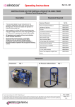
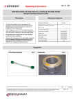
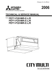
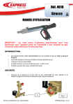
Ref: OI - 002
Operating Instructions
SIROCCO TUBE INTEGRITY & LENGTH TESTER
(STILT)
Description
Equipment Required
Equipment Required:
•
Provides a method for determining the length of a blown
fibre tube.
•
Provides a method for pressure testing a length of blown
fibre tubing.
The determination of the route length must be
undertaken prior to the pressure testing of the route
unless a period of 15 minutes has elapsed between
the tests.
Part No.
Sirocco Compressor (Petrol) or
XBFSC00002
220/240v DC (Electric)
XBFSC00013
STILT
XBFSC00030
Tube End Stop
XBFSC00076
Tube Cutter (part of kit 820/5) or
XBFSC00011
•
Provides a method for checking for and clearing water
from a blown fibre tube.
Individually
XBFSC00078
Air stone (part of kit 820/5) or
XBFSC00011
•
Provides a method for checking for blockages within a
blown fibre tube.
Individually
XBFSC00052
•
All operators must comply with any local statutory
Health & Safety regulations.
5 – 5mm Tube Connector
XBFSC00075
•
Working with Compressed Air is potentially
dangerous and any operator following these
procedures must have successfully completed a
Prysmian Cables & Systems UK Ltd approved training
course.
Equipment
STILT
Qty 1
Compressor
Qty 1
Prysmian Cables & Systems UK Ltd 2007. All Rights Reserved.
The information contained within this document must not be copied, reprinted or reproduced in any form, either wholly or in part, without the written consent of
Prysmian Cables & Systems UK Ltd. The information is believed correct at the time of issue. Prysmian Cables & Systems UK Ltd reserves the right to amend
this specification without notice. This specification is not contractually valid unless specifically authorised by Prysmian Cables & Systems UK Ltd.
RSu
01/2007
Page 1 of 10
Ref: OI - 002
Operating Instructions
Ancillary Equipment
Tube End Stop
Qty 1
Tube Cutter
Air Stone
Qty 1
5 - 5mm Tube Connector
Qty 1
Qty 1
Prysmian Cables & Systems UK Ltd 2007. All Rights Reserved.
The information contained within this document must not be copied, reprinted or reproduced in any form, either wholly or in part, without the written consent of
Prysmian Cables & Systems UK Ltd. The information is believed correct at the time of issue. Prysmian Cables & Systems UK Ltd reserves the right to amend
this specification without notice. This specification is not contractually valid unless specifically authorised by Prysmian Cables & Systems UK Ltd.
RSu
01/2007
Page 2 of 10
Ref: OI - 002
Operating Instructions
Measurement of the Length of a Blown Fibre Tube
Step 1
Step 2
Step 3
•
•
•
Identify the tube to be tested and ensure
that the ends of the tube are cut cleanly.
Place a Tube Sealing Cap onto the tube
at the remote end of the route. Ensure
that the sealing cap is tightened fully.
Connect the compressor hose to the
STILT.
Step 4
Step 5
Step 6
•
•
•
Close the inlet valve.
Close the outlet valve.
Start the compressor
Step 7
Step 8
Step 9
•
•
•
Open the compressor valve.
Open the inlet valve.
Fill the reservoir with compressed air.
This will take approx. 2 minutes.
Prysmian Cables & Systems UK Ltd 2007. All Rights Reserved.
The information contained within this document must not be copied, reprinted or reproduced in any form, either wholly or in part, without the written consent of
Prysmian Cables & Systems UK Ltd. The information is believed correct at the time of issue. Prysmian Cables & Systems UK Ltd reserves the right to amend
this specification without notice. This specification is not contractually valid unless specifically authorised by Prysmian Cables & Systems UK Ltd.
RSu
01/2007
Page 3 of 10
Ref: OI - 002
Operating Instructions
Step 10
Step 11
Step 12
•
•
•
Close the inlet valve. If the air pressure
indicated on the gauge, drops below 10
bars open the inlet valve and continue to
fill the reservoir.
Using the system vent valve regulate the
gauge needle to lie on the start line.
During the adjustment process if the air
pressure drops below 10 bars open the
inlet valve to increase the air pressure
within the reservoir. Repeat Step 12
Step 13
Step 14
Step 15
•
•
•
Close the compressor valve.
Switch off the compressor.
Connect the tube to the STILT using
the correct connector. An extension
piece of tubing can be used if required.
Step 16
Step 17
Step 18
•
•
•
Open the outlet valve
The pressure gauge will indicate a
pressure drop. Wait until the gauge
needle stops falling.
This will take up to 10 minutes.
When the gauge needle has stopped
falling the length of the route can be
read from the gauge.
If the gauge needle falls to 0 this indicates
that there is an air leak in the tube.
Ensure that the reading is taken from the
appropriate scale that corresponds to the
tube size.
Prysmian Cables & Systems UK Ltd 2007. All Rights Reserved.
The information contained within this document must not be copied, reprinted or reproduced in any form, either wholly or in part, without the written consent of
Prysmian Cables & Systems UK Ltd. The information is believed correct at the time of issue. Prysmian Cables & Systems UK Ltd reserves the right to amend
this specification without notice. This specification is not contractually valid unless specifically authorised by Prysmian Cables & Systems UK Ltd.
RSu
01/2007
Page 4 of 10
Ref: OI - 002
Operating Instructions
Step 19
•
Open the system vent valve and allow the
air pressure to decrease to 0.
Pressure Testing of a Blown Fibre Tube
Following On From Step 19
Step 20
Step 21
Step 22
•
•
Start the compressor.
Close the inlet valve.
Close the outlet valve.
Step 23
Step 24
Step 25
•
•
•
Open the compressor valve.
Open the inlet valve.
Open the outlet valve.
Prysmian Cables & Systems UK Ltd 2007. All Rights Reserved.
The information contained within this document must not be copied, reprinted or reproduced in any form, either wholly or in part, without the written consent of
Prysmian Cables & Systems UK Ltd. The information is believed correct at the time of issue. Prysmian Cables & Systems UK Ltd reserves the right to amend
this specification without notice. This specification is not contractually valid unless specifically authorised by Prysmian Cables & Systems UK Ltd.
RSu
01/2007
Page 5 of 10
Ref: OI - 002
Operating Instructions
Step 26
Step 27
Step 28
•
•
•
Allow the route to become pressurised to
above 10 bars.
Close the inlet valve.
Shut the compressor valve.
This may take up to 10 minutes.
Step 29
Step 30
Step 31
•
•
•
Switch off the compressor.
Step 32
Note the pressure at which the route is
fully pressurised.
If the air pressure drops below this
figure and continues to drop to 0 it
indicates that there is a leak in the
route.
Step 33
X
•
Under no circumstances should the
installation of the blown fibre commence
until the cause of the leak has been
identified and repaired.
•
Open the vent valve and allow the air
pressure to decrease to 0.
Prysmian Cables & Systems UK Ltd 2007. All Rights Reserved.
The information contained within this document must not be copied, reprinted or reproduced in any form, either wholly or in part, without the written consent of
Prysmian Cables & Systems UK Ltd. The information is believed correct at the time of issue. Prysmian Cables & Systems UK Ltd reserves the right to amend
this specification without notice. This specification is not contractually valid unless specifically authorised by Prysmian Cables & Systems UK Ltd.
RSu
01/2007
Page 6 of 10
Ref: OI - 002
Operating Instructions
Test Procedure (Checking for Water)
Following On From Step 33
Step 34
Step 35
Step 36
•
Remove the tube end stop at the remote
end of the route and connect a short section
of blown fibre tube to the route end.
During the test a person should hold this
extra section of tube to ensure that it is not
pointing at anyone and that anything being
blown out of the blown fibre tube is not a
hazard to anyone.
•
•
Step 37
Step 38
Step 39
•
•
•
Push the sponge into the tube.
Remove the blown fibre tube at the
output side of the STILT.
Connect the blown fibre tube to the
STILT.
Insert a small piece of sponge (10mm
long x 5mm dia) into the blown fibre
tube.
Close the outlet valve on the STILT.
Step 37
Step 38
Step 39
•
•
•
Start the Compressor and open the outlet
valve on the compressor.
Open the Inlet valve on the STILT.
Allow the pressure within the STILT to
build-up to 10 bar.
Prysmian Cables & Systems UK Ltd 2007. All Rights Reserved.
The information contained within this document must not be copied, reprinted or reproduced in any form, either wholly or in part, without the written consent of
Prysmian Cables & Systems UK Ltd. The information is believed correct at the time of issue. Prysmian Cables & Systems UK Ltd reserves the right to amend
this specification without notice. This specification is not contractually valid unless specifically authorised by Prysmian Cables & Systems UK Ltd.
RSu
01/2007
Page 7 of 10
Ref: OI - 002
Operating Instructions
Step 40
Step 41
Step 42
•
•
•
Open the outlet valve on the STILT.
The sponge will be blown through the
route removing any water that is trapped
in the blown fibre tube.
Step 43
Step 44
•
•
Close the outlet valve on the compressor
and switch it off in the recommended
manner.
If water is seen to be removed from the
route repeat steps 27 to 34 again.
Do not attempt to disconnect any of the
blown fibre tube until the entire route is at
atmospheric pressure.
Using the vent valve on the STILT vent
the air within the blown fibre route to
atmospheric pressure.
Do not attempt to disconnect any of the
blown fibre tube until the entire route is at
atmospheric pressure.
Test Procedure (Checking For Blockages)
Following On From Step 44
Step 45
Step 46
Step 47
•
•
•
At the remote end fit a ceramic stone.
Remove the blown fibre tube at the
output side of the STILT.
Cut off a sample of 4 fibre unit between
150 – 200mm long.
Prysmian Cables & Systems UK Ltd 2007. All Rights Reserved.
The information contained within this document must not be copied, reprinted or reproduced in any form, either wholly or in part, without the written consent of
Prysmian Cables & Systems UK Ltd. The information is believed correct at the time of issue. Prysmian Cables & Systems UK Ltd reserves the right to amend
this specification without notice. This specification is not contractually valid unless specifically authorised by Prysmian Cables & Systems UK Ltd.
RSu
01/2007
Page 8 of 10
Ref: OI - 002
Operating Instructions
Step 47
Step 48
Step 49
•
•
•
Using a pair of pliers crimp a Blown Fibre
Bead onto both ends of the fibre unit.
Gently shake the fibre unit to ensure that
the Blown Fibre beads are fixed to the
fibre unit. If any fall off fit a new Blown
Fibre Bead.
Insert the 100mm long piece of fibre
unit into the blown fibre tube.
Step 50
Step 51
Step 52
•
•
•
Connect the blown fibre tube to the STILT.
Close the outlet valve on the STILT.
Start the Compressor and open the
outlet valve on the compressor.
Step 53
Step 54
Step 55
•
•
•
Open the Inlet valve on the STILT.
Allow the pressure within the STILT to
build-up to 10 bar.
Open the outlet valve on the STILT.
Prysmian Cables & Systems UK Ltd 2007. All Rights Reserved.
The information contained within this document must not be copied, reprinted or reproduced in any form, either wholly or in part, without the written consent of
Prysmian Cables & Systems UK Ltd. The information is believed correct at the time of issue. Prysmian Cables & Systems UK Ltd reserves the right to amend
this specification without notice. This specification is not contractually valid unless specifically authorised by Prysmian Cables & Systems UK Ltd.
RSu
01/2007
Page 9 of 10
Ref: OI - 002
Operating Instructions
Step 56
Step 57
Step 58
•
•
No Picture
•
The fibre sample will be blown through the
route at very high speed.
In the event of there being no kinks or
blockages in the blown fibre tube the
sample will be caught in the ceramic
stone.
Step 56
Step 57
•
•
Close the outlet valve on the compressor
and switch it off in the recommended
manner.
If after a period of 20 minutes the fibre
has not arrived at the air stone then this
indicates that there is a blockage in the
route.
Using the vent valve on the STILT, vent
the air within the blown fibre route to
atmospheric pressure.
Do not attempt to disconnect any of the
blown fibre tube until the entire route is at
atmospheric pressure.
Prysmian Cables & Systems UK Ltd 2007. All Rights Reserved.
The information contained within this document must not be copied, reprinted or reproduced in any form, either wholly or in part, without the written consent of
Prysmian Cables & Systems UK Ltd. The information is believed correct at the time of issue. Prysmian Cables & Systems UK Ltd reserves the right to amend
this specification without notice. This specification is not contractually valid unless specifically authorised by Prysmian Cables & Systems UK Ltd.
RSu
01/2007
Page 10 of 10