1
Ref: OI - 005
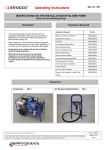
Operating Instructions
INSTRUCTIONS ON THE INSTALLATION OF BLOWN FIBRE
(Range Extending using the Coiler)
Description
Equipment Required
Equipment Required:
•
•
This document details the user instructions for the
installation of MK2 Blown Fibre Units using the Sirocco
Blowing Head. This document details the operation of
Range Extending using the Coiler.
Part No.
Equipment as detailed in document:
Ref: OI - 011
When installing 2 or 4 fibre EPFU the same fibre guides
within the blowing head can be used. When installing an 8
or 12 fibre unit it is necessary to change the fibre guides.
•
All operators must comply with any local statutory
Health and Safety regulations.
•
Working with compressed air is potentially dangerous
and any operator following these procedures must
have successfully completed a Prysmian Cables &
Systems UK Ltd approved training course.
Plus items required are:
Close Down Assembly
XBFSC00041
Inverter Pan
XBFSC00009
Blown Fibre Coiler
XBFSC00008
Pan Guide
XBFSC00043
Pan Guide Support
XBFSC00055
110v Power Supply
n/a
Equipment
Close Down Assembly
Qty 1
Inverter Pan
Prysmian Cables & Systems UK Ltd 2006. All Rights Reserved.
The information contained within this document must not be copied, reprinted or reproduced in any form, either wholly or in part, without the written consent of
Prysmian Cables & Systems UK Ltd. The information is believed correct at the time of issue. Prysmian Cables & Systems UK Ltd reserves the right to amend
this specification without notice. This specification is not contractually valid unless specifically authorised by Prysmian Cables & Systems UK Ltd.
Qty 1
RSu
02/2006
Page 1 of 9
Operating Instructions
Ref: OI - 005
Equipment (contd.)
Blown Fibre Coiler
Qty 1
Pan Guide
Qty 1
Pan Guide Support
Qty 1
110v Power Supply (transformer)
Qty 1
Summary
An installation, utilising Range Extending Techniques for distances greater than those recommended,
potentially has many parts. The first part can be considered a ‘Point to Point’ installation and the
procedure therefore is documented in procedure OI – 001.
The second and subsequent parts of an installation using these Range Extending Techniques are
detailed in this document, and cross-references procedure OI – 001.
N.B.
Having completed the first half of the installation of the fibre unit, the settings on the Blowing Head
remain the same for the second part of the installation. There is no adjustment required.
Prysmian Cables & Systems UK Ltd 2006. All Rights Reserved.
The information contained within this document must not be copied, reprinted or reproduced in any form, either wholly or in part, without the written consent of
Prysmian Cables & Systems UK Ltd. The information is believed correct at the time of issue. Prysmian Cables & Systems UK Ltd reserves the right to amend
this specification without notice. This specification is not contractually valid unless specifically authorised by Prysmian Cables & Systems UK Ltd.
RSu
02/2006
Page 2 of 9
Ref: OI - 005
Operating Instructions
Blowing Head Preparation
Refer to procedure OI – 001, and follow steps 1 – 29.
Proving the Route
The route should be proved using the Sirocco Tube Integrity and Length Tester (STILT), this will determine the length, and
whether there are any air leaks along the route. These procedures are detailed in procedure OI – 002.
Upon completion of this refer to procedure OI – 001 and follow steps 31 – 41.
Installing the Fibre Unit
Refer to procedure OI – 001, and follow steps 42 – 67.
Coiling the Fibre Unit
Step 1
Step 2
Step 3
•
•
•
Having blown in the first part of the fibre
unit (as detailed in document OI – 001),
remove the Air Stone and blow through
a further 4 or 5 metres.
Site the base of the coiler on a level
surface in line with the tube end bearing
the fibre unit, and ideally, within 2 – 3
metres of the tube end. Uncoil the lead
in the base of the coiler
Release the four catches and remove
the TOP end from an empty Inverter
Pan. Place the Pan over the coiler.
Prysmian Cables & Systems UK Ltd 2006. All Rights Reserved.
The information contained within this document must not be copied, reprinted or reproduced in any form, either wholly or in part, without the written consent of
Prysmian Cables & Systems UK Ltd. The information is believed correct at the time of issue. Prysmian Cables & Systems UK Ltd reserves the right to amend
this specification without notice. This specification is not contractually valid unless specifically authorised by Prysmian Cables & Systems UK Ltd.
RSu
02/2006
Page 3 of 9
Ref: OI - 005
Operating Instructions
Step 5
Step 4
Wide
grooved
wheel
•
Secure the Pan Guide Support to the
Inverter Pan.
Step 6
Narrow
grooved
wheel
•
Ensure the correct wheel is fitted to the
coiling head.
•
NB. The wheel with the narrower groove
is for 2 and 4-fibre unit, and the wider
grooved wheel is for 8 and 12 fibre unit.
•
Locate the coiler head on the drive
spindle of the coiler. Press the locking
knob through the aperture at the back of
the head to drop the head assembly fully
down onto the drive spindle. Hold the
feed wheel and rotate the head assembly
until the head locks with a definite click.
Step 7
Step 8
Step 9
•
•
•
Pass the end of the 4 or 5 metres of
fibre unit through the Pan Guide.
The end of the fibre unit should be taped
to the floor of the pan. Position the fibre
unit between the wheel and the guide
rollers.
Place the Pan Guide onto the Support
frame and secure in place.
Prysmian Cables & Systems UK Ltd 2006. All Rights Reserved.
The information contained within this document must not be copied, reprinted or reproduced in any form, either wholly or in part, without the written consent of
Prysmian Cables & Systems UK Ltd. The information is believed correct at the time of issue. Prysmian Cables & Systems UK Ltd reserves the right to amend
this specification without notice. This specification is not contractually valid unless specifically authorised by Prysmian Cables & Systems UK Ltd.
RSu
02/2006
Page 4 of 9
Ref: OI - 005
Operating Instructions
Step 10
Step 11
Step 12
This space has been left blank
intentionally
•
Connect the leads from the 110v power
supply and from the coiler to the control
unit.
Step 13
•
Ensure the reset button has zeroed the
length indicator, and that the on / off
switch is in the OFF position
•
Back at the blowing position re-start
blowing the fibre unit.
•
At the same time, at the coiling end,
switch on the coiler. As the fibre is
blown in the coiler will coil the fibre unit
into the Inverter Pan for the next part of
the installation.
Step 14
Step 15
•
•
This space has been left blank
intentionally
•
When the required amount of fibre unit
has been coiled, stop the blowing
operation and stop the coiler.
Using the finger grip, gently pull the
roller chain away from the feed wheel
and remove the fibre unit.
Remove the Pan Guide and lay on its
side, ensuring no damage to the fibre
unit.
Prysmian Cables & Systems UK Ltd 2006. All Rights Reserved.
The information contained within this document must not be copied, reprinted or reproduced in any form, either wholly or in part, without the written consent of
Prysmian Cables & Systems UK Ltd. The information is believed correct at the time of issue. Prysmian Cables & Systems UK Ltd reserves the right to amend
this specification without notice. This specification is not contractually valid unless specifically authorised by Prysmian Cables & Systems UK Ltd.
RSu
02/2006
Page 5 of 9
Ref: OI - 005
Operating Instructions
Step 16
Step 17
Step 18
This space has been left blank
intentionally
•
Remove the Pan Guide Support from
the Pan passing the fibre unit through
the gap in the belt of the support.
•
Remove the head assembly from the
base of the coiler by pressing the
locking knob and lifting the head
upwards. To prevent damage always
store head in box after use.
•
Carefully lift the Inverter Pan off the
base of the coiler.
Operating the Inverter Pan
Step 19
Step 20
This space has been left blank
intentionally
•
If the pan is to be moved for the second
blowing operation, withdraw sufficient
fibre unit to allow for this.
Step 21
Upper slot
•
Place the fibre unit emerging from the
pan in the upper slot of the sliding door.
•
Replace the TOP end of the Inverter
Pan, taking care not to trap the fibre
unit, and secure the four catches.
Prysmian Cables & Systems UK Ltd 2006. All Rights Reserved.
The information contained within this document must not be copied, reprinted or reproduced in any form, either wholly or in part, without the written consent of
Prysmian Cables & Systems UK Ltd. The information is believed correct at the time of issue. Prysmian Cables & Systems UK Ltd reserves the right to amend
this specification without notice. This specification is not contractually valid unless specifically authorised by Prysmian Cables & Systems UK Ltd.
RSu
02/2006
Page 6 of 9
Ref: OI - 005
Operating Instructions
Step 22
Step 23
Step 24
•
•
This space has been left blank
intentionally
•
With the sliding door on the far side of
the pan, lift the pan using its handles
and turn it upside down smartly whilst
keeping the sliding door on the opposite
side.
Lower the pan to the ground and check
that the fibre unit is not trapped beneath
the pan. The BOTTOM end of the pan
will now be uppermost.
Remove the BOTTOM of the pan and
the end of the fibre unit will be taped to
the inside.
Step 25
Step 26
Step 27
•
•
•
Take the fibre unit out of the slot in the
sliding door and secure to the underside
of the Pan Guide with tape.
Step 28
Pass the END of fibre unit through the
Pan Guide.
Step 29
Step 30
This space has been left blank
intentionally
This space has been left blank
intentionally
•
The Blowing Head is now moved to,
what was the coiling end, and set up
ready for onwardly blowing the fibre unit.
Place the Pan Guide onto the Pan and
secure the first length of installed fibre to
the top of the Pan Guide as shown.
•
A Close Down Assembly is fitted to the
tube into which the fibre unit is about to
be blown.
•
If the installation requires more blow on
and coil procedures then at this stage,
re-site the coiler at the next coiling
position and repeat steps 1 – 35 of this
document.
Prysmian Cables & Systems UK Ltd 2006. All Rights Reserved.
The information contained within this document must not be copied, reprinted or reproduced in any form, either wholly or in part, without the written consent of
Prysmian Cables & Systems UK Ltd. The information is believed correct at the time of issue. Prysmian Cables & Systems UK Ltd reserves the right to amend
this specification without notice. This specification is not contractually valid unless specifically authorised by Prysmian Cables & Systems UK Ltd.
RSu
02/2006
Page 7 of 9
Ref: OI - 005
Operating Instructions
Proving the Route
The route should be proved using the Sirocco Tube Integrity and Length Tester (STILT), this will determine the length, and
whether there are any air leaks along the route. These procedures are detailed in procedure OI – 002.
Upon completion of this refer to procedure OI – 001 and follow steps 31 – 41.
Installing the Fibre Unit
Refer to procedure OI – 001, and follow steps 42 – 60.
Closing Down at the Blowing Position
Step 31
Step 32
Step 33
As the fibre unit is installed into the route the
last few coils will leave the pan, slow the
installation speed down and remove the two
pieces of tape securing the original side of
the fibre unit to the pan guide, and allow the
fibre to run freely out of the pan.
•
•
Inch in the last few metres of the fibre
unit whilst holding the rear tube, until
this tube is pulled just up against the
back of the blowing head, ensuring no
strain is put on the fibre.
At this point, turn the installation speed
control to 0 and turn off the air at the
compressor valve.
Refer to procedure OI – 001 and follow steps 62 through 67
Prysmian Cables & Systems UK Ltd 2006. All Rights Reserved.
The information contained within this document must not be copied, reprinted or reproduced in any form, either wholly or in part, without the written consent of
Prysmian Cables & Systems UK Ltd. The information is believed correct at the time of issue. Prysmian Cables & Systems UK Ltd reserves the right to amend
this specification without notice. This specification is not contractually valid unless specifically authorised by Prysmian Cables & Systems UK Ltd.
RSu
02/2006
Page 8 of 9
Operating Instructions
Ref: OI - 005
Closing Down at the Blowing Position (contd).
Step 34
Step 35
•
•
Carefully remove the blown fibre tube and
fibre unit from the blowing head whilst
maintaining the gap left by the blowing
head between the tubes.
Remove the split ‘O’ ring from the tube,
and slide the Close Down Assembly
along the tube to cover the gap in the
tube. Tighten in place.
Prysmian Cables & Systems UK Ltd 2006. All Rights Reserved.
The information contained within this document must not be copied, reprinted or reproduced in any form, either wholly or in part, without the written consent of
Prysmian Cables & Systems UK Ltd. The information is believed correct at the time of issue. Prysmian Cables & Systems UK Ltd reserves the right to amend
this specification without notice. This specification is not contractually valid unless specifically authorised by Prysmian Cables & Systems UK Ltd.
RSu
02/2006
Page 9 of 9