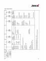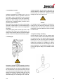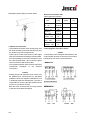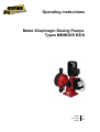
1
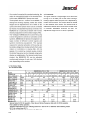
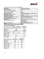
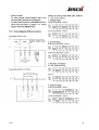
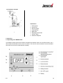
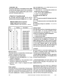
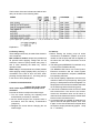
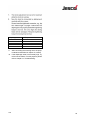
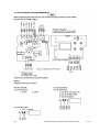
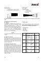
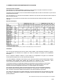
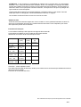
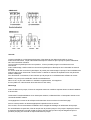
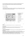
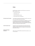
Operating instructions
Motor-Diaphragm Dosing Pumps
Types MEMDOS E/DX
Dosing
Conveying
Control
Liquids
Gases
Systems
Operating instructions
MEMDOS E/DX Lutz-Jesco
GmbH, 2003
Address:
Lutz-Jesco GmbH Am
Bostelberge 19 D30900 Wedemark PO
Box 10 01 64 D-30891
Wedemark
Tel.: +49 (0) 51 30 58 02-0
Fax: +49 (0) 51 30 58 02 6
Représenté par:
Rue de la Légende 41
4141 LOUVEIGNE
Belgique
Tel : +32 4 358 00 12
Fax : +32 4 358 00 14
[email protected]
www.hesperia.be
9.03
3
11. Maintenance................................................................................................................. 22-25
11.1 Lubrication...................................................................................................... 22
11.2 Maintenance of bearings ................................................................................ 22
11.3 Replacing the diaphragm........................................................................... 22-23
11.4 Circuit diagram electronic MEMDOS DX................................................... 24-25
12. Explosion-proof dosing pumps........................................................................................ 25
12.1 General .......................................................................................................... 25
12.2 Special conditions .......................................................................................... 25
12.3 Dosing of flammable media............................................................................ 25
13. Spare parts........................................................................................................................ 25
14. Troubleshooting ................................................................................................................ 26
15. Notice d’utilisation en français
16. Certificate of conformity .................................................................................................. 27-29
Hypalon® and Viton® are registered trademarks of DuPont Dow Elastomers
Teflon® is a registered trademark of the DuPont Company Hastelloy® is a
registered trademark of Haynes International, Inc
9.03
4
1. Safety
1.1 General
This Operating Manual contains basic information
to be noted during installation, operation and
maintenance. It is therefore essential that the Manual
be read by the fitter before installing and
commissioning the pump/system, as well as by the
relevant operating personnel / owner of the pump/
system. It must remain accessible at the pump/
system for reference at all times. In addition to the
general safety instructions set out under this main
heading Safety, the special safety precautions set
out under the other main headings must also be
observed, for instance in conjunction with private
use.
1.2 Warnings used in this Operating Manual
This Operating Manual contains warnings which may
endanger persons, the environment and the pump/
system if they are disregarded. These warnings are
identified by the hazard symbol
safety mark in accordance with DIN 4844-W9
The following symbol is used in conjunction with
electric power
safety mark in accordance with DIN 4844-W8
The word
Caution
appears in conjunction with safety instructions
which may endanger the machine and its operation
if disregarded.
Markings which are affixed directly to the pump,
such as
- Direction of rotation arrow
- Markings for fluid connections
9.03
5
- Leakages (e.g. at the shaft seal) of hazardous
substances (e.g. explosive, toxic, hot substances)
must be discharged in such a way as to exclude
all danger to persons and the environment.
Statutory regulations must be observed.
- Danger due to electric power must be excluded
(for further details, refer to the VDE regulations and
the regulations of the local public utilities).
- Separate regulations must be observed if the dosing
pumps are operated in explosion-hazard areas. The
explosion hazard must be defined (classification
of zones) and appropriate equipment selected by
the owner. Further information can be found in
section 7.1 (Installation), section 7.5 (Electrical
connection) and section 12 (Explosion-proof dosing
pumps).
1.7 Safety instructions for inspection,
maintenance and installation work
The owner must ensure that all maintenance,
inspection and installation work is undertaken by
authorized and duly qualified skilled personnel who
have also studied the Operating Manual in depth.
The pump must always have come to a complete
stop before starting any work on the pump. The
procedure specified in the Operating Manual for
shutting down the pump/system must be observed
without fail.
Pumps or units in contact with potentially harmful
media must be decontaminated. All safety
mechanisms and guards must be refitted and
reactivated as soon as the work is complete.
Particular care must be taken when repairing dosing
pumps which are used in explosion-hazard areas.
Due to the risk of sparking, care must be taken to
prevent metal parts or tools knocking against one
another. The dosing pump should preferably be
moved out of the explosion-hazard area in order to
be repaired.
The points set out in the section Installation and
commissioning must be observed before starting the
pump/system.
9.03
1.8 Unauthorized modification and production
of spare parts
The machine may only be modified or converted in
consultation with the manufacturer. Genuine spare
parts and accessories authorized by the
manufacturer ensure greater safety. Liability for
damage or loss may be extinguished if other parts
are used.
1.9 Impermissible modes of operation
The operational safety of the pump supplied can
only be guaranteed when it is used in conformity
with its intended use as specified in our contract
documents, especially the letter confirming the
order. The limit values specified in these documents
must never be exceeded.
1.10 Dosing of chemicals
- When working on dosing installations, the local
safety rules must be observed (e.g. wear personal
protective clothes).
- Before working on the dosing pump and plant,
disconnect it from the mains supply and protect it
against reconnection. Before the power supply is
switched on again, the dosing lines must be
connected so that any chemical left in the dosing
head cannot spurt out.
- The dosing head of the pump as well as connections
and lines of the plant may be under pressure.
Working on the dosing plant requires special safety
precautions and may only be carried out by
instructed technical personnel.
- Before startup, all screwed connections must be
checked for correct tightness and, if necessary,
must be tightened up using appropriate tools.
- If connections at the dosing head are unscrewed
during operation for venting or other reasons, leaking
chemical must be removed professionally. This is
the only way to avoid the danger of physical injury
and corrosion at the dosing pump. Leaking chemical
might also destroy the diaphragm at its mounting
points.
6
- When changing the chemical, check whether the
materials used for the dosing pump and the other
plant parts are chemically resistant. If there is the
danger of a chemical reaction between different
media, a thorough cleaning first is mandatory.
To operate the pump mount the fan shell in order
to ensure sufficient cooling of the motor.
Protective class of the control unit is only reached
if ports are protected by caps or serial plug-in
connectors are used.
Note
Under certain operating conditions, the drive motor
of the DX version might warm up considerably. To
avoid unintentional contact, provide an appropriate
device.
Adjustment works in the interior of the ATE drive
(optional at MEMDOS E) must be carried out
carefully. Connections and internal limit switches
might be "alive".
- Additional limit switches might be "alive" even with
the auxiliary voltage switched off (ATE-drive).
- After installation works at the ATE servomotor or
before startup remount the cover.
9.03
1.11 Scope of delivery
Note
Please unpack the dosing pump and ordered
accessories carefully in order not to miss small
parts. Immediately compare the scope of delivery
to the delivery note. If there are any discrepancies,
try to find out the reason.
For the transportation of the dosing pumps, no
special fittings are required. It is, however, advisable
to choose a transportation method, which is
appropriate for the weight of the dosing pumps (e.g.
wagon). During transportation without oil, the dosing
pump should be lying. Otherwise it must be
tightened to the transportation device.
2. General, purpose
The MEMDOS E/DX may only be used in
accordance with the specifications in the Technical
Data. Local regulations must be observed. Suitable
materials must be selected. The operating manual
must be consulted for installation, commissioning
and maintenance of the dosing pump. Dosing
pumps are produced according to highest quality
standards and have a long service life.
Nevertheless some parts are subject to wear (e.g
diaphragm, valve seats, valve balls). To ensure long
operating life, visual checks are required regularly.
Operating and maintenance personnel must be able
to access the pump easily. The MEMDOS E can
be operated in explosion-hazard areas of zone 1 if
the corresponding drive is taken into account.
Further information can be found in the operating
manual.
Diaphragm dosing pumps from the MEMDOS series
are used in industry, in the process engineering
sector, as well as in water and wastewater
processing. Two models of the MEMDOS E/DX
are available:
1. 0...4 bis 0...160 l/h and
2. 0...160 bis 0...380 l/h
7
3. Functional
The gear contains a single-stage worm wheel set
runing in an oil bath just as the roller bearings.
Dosing happens while the push rod is displaced by
means of an eccentric. The suction stroke is caused
by the resetting of the spring. The stroke length is
adjusted by limiting return travel of the poppet using
a manually adjustable eccentric as stop. An
adjustment range from 0 to 100% is possible.
4.1 Technical data
9.03
8
9.03
9
9.03
10
0
1
2
3
4
5
6
7
8
9 10
Stroke adjustment
0
4
1
2
3
4 5 6 7 8
Stroke adjustment
9 10
2
11
1bar
3bar
5bar
9.03
12
9.03
13
9.03
14
9.03
15
7.2 Installation location
Caution
Ambient temperatures exceeding 40°C are not
permitted. Radiant heat of apparatus and heat
exchangers must be shielded so that the dosing
pump can still dissipate its own heat sufficiently.
Exposure to direct sunlight must be avoided. If the
dosing pump is installed outside, provide a roof to
protect it against weather.
Mount the pump so that the suction and discharge
valve are in vertical position. To ensure that the pump
stands firm, fasten it with screws on an appropriate
foundation.
The system piping must not exert any force on the
connections and valves of the metering pump. To
avoid incorrect metering after the process is finished,
provide an electric and hydraulic interlocking system.
7.3 Drain pipe
a downward slope - above which the pipe ends at a
sufficient distance. Leakage can be returned via the
funnel through the tank cover. Besides, possible
leakage can be seen at the funnel.
Caution
If a leakage monitor is installed in the explosionhazard area, the electrical connection must be
intrinsically safe. The drive motor must be electrically
interlocked to prevent additional medium escaping
if a leak occurs.
7.4 Injection fitting assembly
Injection fittings are used to mix the metered medium into a main stream and simultaneously fulfil a
non-return function. The injection fitting is usually
installed in the main line from above. Installation
from below is only recommended in the case of
media with a tendency to crystallize, in order to
ensure that air bubbles are not entrapped. For this
type of installation, it is advisable to select a form
in which the injection fitting can be sealed off when
removed.
Caution
Drainage or leakage from the separating chamber
must be routed with a certain downward slope to the
containment tank. By no means must the drain pipe
be returned directly to the chemical through the tank
cover because otherwise effervescent media might
enter the pump gear. The drain pipe may only be
routed to a collecting tank free of gases (with a
downward slope) or to a collecting funnel - also with
9.03
16
Extractable injection fitting from down below
Electrical connection data
(other types upon request)
Pump
size
Voltage
[Volt]
Power
[Watt]
Current
[A]
MEMDOS
400/230
50
0.50/0.87
50
0.70
250
0.90/1.55
E4 ... 50
MEMDOS
E/DX 4 ... 26
MEMDOS
3~ 50 Hz
230 1~ 50
Hz
400/230
E50 ... 156
MEMDOS
E/DX50 ... 156
3~ 50 Hz
230 1~ 50
Hz
120
1.15
400/230
370
1.06/1.84
250
2.25
MEMDOS
7.5 Electrical connection
- The electrical connection of the dosing pump must
be made according to the local rules and may only
be carried out by technical personnel.
- Cable type und cable cross section of the supply
lines must be selected according to the motor data.
- The cable passage to the motor terminal box must
be made professionally. We recommend gland
screw connections with traction relief.
- The required protection class must be ensured by
professional installation of the electrical
connections.
E160 ... 380
3~ 50 Hz
MEMDOS
E/DX160 ... 380
230 1~ 50
Hz
Circuit diagram of the drive motor
Caution
To avoid early wear of the gear drive adhere to the
correct rotation direction of the motor by all means:
looking at the fan wheel, counterclockwise.
- MEMDOS E
Caution
- Dosing pumps with explosion-proof motors must
be installed and commissioned by specialists
qualified to work with equipment destined for use
in potentially explosive atmospheres. The user is
responsible for ensuring that the explosion-proof
motors are connected correctly.
- Both the motor and the pump must be grounded
to prevent electrostatic discharges.
9.03
17
9.03
18
7.6 Installation example
3
Explanation
4
2
1
2
3
4
5
6
7
8
Dosing pump
Suction line
Electric agitator
Chemical tank
Relief valve
Diaphragm shutoff valve
Injection fitting
Pulsation dampener
8. Operating
8.1 Operating panel MEMDOS DX
The operating panel has two green LEDs for operation and external control, one red LED for alarm, one 3digit multifunctional display and four keys for settings. The inputs for remote switchoff, low level indication
and external control are located below the display.
20
Technical changes are always reserved without notice.
9.03
The functions of the two indicators and built-in fault
relay can be seen in the following table:
*) LED 2 lights up in operating modes 1.1 - 1.64; 0...20 mA and 4... 20 mA
Explanation:
8.5 Factory setting
These settings should only be made if the electronic
unit is replaced.
Max. number of strokes: Keep the keys Mode and
I/0 pressed while applying voltage and set the
maximum number of pump strokes using keys T
and S. After releasing the Mode key, normal
operation starts.
Alarm relay: If the keys Mode and S bare pressed
while applying voltage (display RE0), the relay is
currentless in the case of error and OFF, when
pressing the keys Mode and T , the relay pulls up
in the case of error (display RE1).
9. Stroke length adjustment
Caution The stroke length
must not be adjusted when the pump is at a
standstill !
Proceed as follows to adjust the stroke length:
1. Turn the screw securing the adjusting knob
anticlockwise (to the left) to release it.
2. Set the stroke length to the required value in
accordance with the delivery characteristics
(chapter 5).
3. Retighten the screw without changing the set
stroke length.
9.03
10. Start up
1. Before starting the dosing pump all works
mentioned in "Installation" (chapter 7) must be
carried out. Fill the pump with the oil supplied. At
the same time the safety instructions must be
observed.
2. The dosing pump MEMDOS E is switched on by
a control to be installed externally.
The MEMDOS DX has its own control system.
Electrical connection and the control system
versions are explained in chapter 8, MEMDOS
DX operating elements.
3. The manual capacity adjustment must be set to
maximum stroke to improve priming. During first
priming no backpressure should be applied. For
this purpose we recommend to install a relief valve
on the discharge side of the dosing pump.
4. A previously installed priming aid must be filled
with chemical first. If the pump is not priming,
remove the discharge valve and fill water or
chemical (if not dangerous!) into the dosing head.
Remount valve and start priming.
5. If a venting facility is available as separate unit,
open it and wait until liquid escapes. Then close
it again. In the case of effervescent liquids allow
the liquid to escape permanently (approx. 1 drop
for 1...3 strokes).
21
6. When correct operation is achieved, set to
required output by means of the adjusting knob
(refer to chapter 9) or the electrical remote
adjustment. For approximation refer to the
performance curves (chapter 5). Depending on the
installation and the chemicals used, these values
may differ and must be checked under operating
conditions.
7. The manufacturer of the metering equipment is
not responsible for damages due to excessive or
low flow rates resulting from faulty pump settings
or incorrect and insufficient installation of
peripheral fittings.
10.1 Start up of MEMDOS E with ATE-servomotor
Switch on the main drive motor of the metering pump.
With an electrical interlocking system, only then can
the ATE drive be adjusted.
To check the direction of rotation send short control
pulses to the ATE servomotor.
If the direction of rotation is wrong, the supply lines
(terminals 2 and 3 in the case of direct controls) are
reversed.
The ATE servomotor must be moved to the final
positions in order to check the limit stop mechanism
of the integrated limit switches. When leaving the
factory, the angle of rotation is 270°. If required, the
angle of rotation and thus the maximum flow rate
can be restricted. To achieve this, the upper trigger
cam is shifted by the required value.
11. Maintenance
11.1 Lubrication
The diaphragm dosing pump MEMDOS E/DX
requires little maintenance. The gear of the pump is
lubricated with gear oil of viscosity class ISO-VG
460 according to DIN 51519 (corresponds to SAE
140 according to DIN 51512). The enclosed first filling
must be renewed after approximately 500 operating
hours. Further oil changes should be carried out every
5,000 operating hours. The filling capacity is about
0.25 l for gears of MEMDOS E/DX up to size 150
and about 0.7 l for gears of MEMDOS E/DX up to
size 380. The actually required quantity of gear oil
can be determined by checking the min.-max.
markings of the oil-measuring stick.
9.03
Caution
DX version: To avoid damaging of the approximation
initiator, the pump must be switched off before
removing the oil gauge.
11.2 Maintenance of bearings
The upper bearing of the pinion shaft is a sealed
and permanently lubricated ball bearing. This function
is simultaneously assumed by the motor bearing
on the output side of the size I MEMDOS E/DX
pumps (up to E/DX 150). The other rolling bearings
in the gearbox and the plain bearings of the
diaphragm rod are lubricated by the gear oil. The oil
also dissipates the heat generated. All bearings
must be examined for wear after 5000 hours of
operation. The service life of the rolling bearings
depends on the loads to which they are subjected.
The bearings must be replaced after 5000 hours of
operation if the dosing pump is operated at
maximum load.
11.3 Replacing the diaphragm
In the case of a rupture the diaphragm can be
replaced as follows:
1. The chemical contained in the metering line is
drained so that the metering lines become
pressureless. Please observe the aforementioned
safety instructions for this purpose.
2. The flow rate of the metering pump is set to zero
while the motor is running. Thus the diaphragm is
moved to its front end position.
3. The head is removed using an appropriate tool.
4. Grasped at the edge, the diaphragm can now be
turned out counterclockwise.
5. Before installing the new diaphragm the
diaphragm flange section must be cleaned of the
chemical. Otherwise the diaphragm might be
attacked from the rear side.
6. The new diaphragm is turned in clockwise until it
sits close (grease screw thread).
22
Diaphragm-ø
52
64
90
120
150
Torque +/- 10%
125 Ncm
2 Nm
6 Nm
6 Nm
10 Nm
9.
After connecting the metering lines, the pump
is started as described in chapter 10, startup.
10. If the diaphragm wear is excessively high, try
to find out the reason. For this purpose, please
refer to chapter 14. Troubleshooting.
9.03
23
24
Technical changes are always reserved without notice.
11.03
External control:
Phono jack (cinch)
1 : Middle contact = input (+) brown
2 : Outer contact = 0 (ground) white
External control:
CSA - variant
3pin plug with cable
1 : Input (+,brown)
2 : 0 (ground, blue)
3 : Not used
Protective class of the control unit is only reached if ports are protected by caps or serial plug-in connectors are
used.
12. Explosion-proof dosing pumps
12.1 General
The MEMDOS E explosion-proof dosing pump is a
motor-driven, explosion-proof diaphragm dosing
pump of equipment category 2, group II. In
combination with an explosion-proof motor (Ex II 2
G E Ex e II T3 or Ex II 2 G E Ex d/de IIB/IIC T4) it is
used to meter liquids in potentially explosive
areas of zone I. The pump bears the Ex identification
”Ex II 2 G c k T4 03 ATEX D085".
Caution
The pump must not be used to meter gaseous media
or solids.
12.2 Special conditions
Compliance with the minimum requirements for the
zone classification must be ensured when using the
dosing pump in potentially explosive areas. Both
the pump itself and the motor must meet with the
minimum requirements.
12.3 Dosing of flammable media
All metal parts in the intake and delivery piping must
be grounded to prevent electrostatic discharges
when dosing explosive liquids. Stainless steel is
recommended for the dosing head. Dosing pumps
with diaphragms measuring more than 90 mm in
diameter are equipped with special conductive
diaphragms to prevent static charging. Only the
original diaphragm may be fitted when ordering
replacement parts.
9.03
13. Spare parts
Genuine spare parts from Lutz-Jesco must be used.
Wear parts for the MEMDOS MR are available as a
set of spare parts containing the following:
- Pump diaphragm
- Valve balls
- Valve seats
- all valve seals
Pump
size
4 ... 26
Material
dosing head / valves
Part No.
PVC/PVDF Viton®
29750
29791
33698
29751
28274
28275
28276
PVC/PVDF PTFE
PVC/PVDF EPDM
1.4571
PVC
PVC
1.4571
PTFE
Hypalon®
Viton®
AF
110 ...
156
PP
Hypalon®
PP
1.4571
Viton
AF
160 ...
260
PP
Hypalon®
PP
1.4571
Viton®
AF
300 ...
380
PP
Hypalon®
50 ... 76
PP
1.4571
®
®
Viton
AF
28300
28301
28302
28308
28309
28310
28316
28317
28318
25
14. Troubleshooting
TYPE OF FAULT
POSSIBLE CAUSE
RECOMMENDED ACTION
Pump not delivering.
Valves leaking.
Clean and remove air from valves.
(See also startup of pump.)
Tighten screw connections.
Valves incorrectly installed.
Reassemble valves. Ensure that the
valve balls of suction and discharge
valve are located above the valve
seats.
Suction filter, foot valve or
suction pipe leaking or
blocked.
Clean and seal suction line.
No stroke movement.
Return spring broken. Replace
spring.
Consider density of the chemical!
Suction lift too high.
Pump delivering too little
or irregularly.
Valves blocked or leaking.
Clean and re-seal valves.
Pump delivering too
much.
Pressure on suction side too
high (pump siphoning).
Install backpressure valve in
discharge line.
Frequent diaphragm.
ruptures.
Diaphragm was not screwed
into diaphragm rod as far as
stop.
Screw in new diaphragm as far
as stop.
Injection nozzle blocked.
Clean injection nozzle; fit larger one, if
necessary.
Pressure peaks because
metering line is too long or
too narrow.
Change line or install pulsation
dampener. For increased safety
install relief valve (see installation
example).
Roller bearing defective.
Replace roller bearing.
No or little oil in gearbox.
Refill oil, as described in
section "maintenance".
Wrong connection.
Check electrical wiring.
Capacitor defective, wrong size
or incorrectly connected.
Connect capacitor correctly or
replace.
Pressure too high.
Check process.
Low level alarm signaling,
Low level main alarm,
internal error.
Check functions as described in
chapter 7 (MEMDOS DX control unit).
Pump very noisy.
Motor hums and
doesn't start.
Indication of alarm states
by red LEDs near display.
If the problem cannot be corrected on the basis of the above data, return the pump to the factory or contact
our Techical Sales Service for further measures. Repairs will be carried out immediately
26
15. MEMDOS E/DX NOTICE DE MAINTENANCE ET D'UTILISATION
Instructions dès réception
Faire attention en ouvrant l'emballage contenant la pompe doseuse, les petits accessoires de celle-ci
(raccord, huile, etc.) sont livrés en vrac dans le même carton.
Comparer le bon de livraison avec les marchandises réceptionnées et avertir te fournisseur au plus vite de
manquements éventuels.
Pour te transport, il n'y a pas de recommandation spécifique, les pompes sont livrées sans huile (l'huile est
dans un flacon externe).
Dans le cas où les pompes sont livrées avec huile, elles doivent être solidement fixées de manière
verticale.
Données techniques
1) Spécial pour fréquence 60Hz
2) Ne peut pas travailler en 60Hz
S
3) Température ambiante : tête PVC (40°C), tête PP ou INOX (60X) et pour court moment 80 C
Installation
Pour le choix de la pompe ou du local où celle-ci sera installée, il faut respecter les régles en vigueur.
Cela s'applique à la sélection du matériel, du mode de transport du liquide et de l'installation
électrique.
Par ex. d'après le tableau ci-dessus, ne pas oublier de comptabiliser la longueur et te diamètre
nominal des tuyauteries pour le choix de la pompe doseuse.
Lors de l'installation, l'utilisateur doit s'assurer qu'une fuite de produit ne puisse endommager d'autres
accessoires (fuite pouvant être causée par rupture de conduite ou de membrane). Nous
recommandons l'installation de sondes de détection de fuite et de bacs de récolte.
Les pompes doseuses sont fabriquées d'après des standards de haute qualité et ont une longue
espérance de vie, sauf les pièces d'usure normale telles que membranes, billes, joints. Pour
s'assurer de la bonne longévité de la pompe, un contrôle régulier est nécessaire.
Pour diminuer les risques de casse en fonctionnement anormal, nous recommandons l'utilisation
d'accessoires tels que soupape de sécurité, soupape de contre pression, sonde de détection de
fuite, sonde de niveau bas et ballons amortisseurs contre les fluctuations de pression.
Pour éviter des dommages aux parties plastiques, il ne faut jamais les serrer trop fortement au risque
de les casser, L'utilisation de vaseline ou de graisse silicone peut aider au montage / démontage des
parties plastiques.
Des modifications techniques peuvent être apportées sans notification
26/2
ATTENTION : Il faut respecter la compatibilité du matériel avec le produit dosé. Une température
ambiante > 40°C n'est pas autorisée sans ventilation forcée. Un chauffage ou échangeur de chaleur
ne peut être installé à proximité pour éviter une surchauffe des pièces plastiques. Une exposition au
soleil est à éviter et si la pompe est montée à l'extérieur, il faut prévoir un toit pour sa protéger des
rayons solaires et des intempéries.
La pompe doit être montée avec les clapets aspiration / refoulement dans un axe vertical. Pour être
certain que celle-ci ne bouge pas, il est recommandé de la fixer sur un support.
Les conduites ne doivent exercer aucune force sur les raccords.
Embout de fuite
Toute fuite via embout doit être dirigée vers un bac récolteur ou une tuyauterie d'évacuation ouverte. En
aucun cas, il ne peut être raccordé à une conduite fermée venant dune cuve d’aspiration pour éviter
des vapeurs de produit vers le réducteur.
Connexions électriques
Le raccordement électrique doit respecter tes régies locales et être fait
par du personnel qualifié. Le type de câble et te diamètre doit être
sélectionner en fonction de la fiche technique moteur.
Pompe
MEMDOS
Voltage
[Volt]
Power
[Watt]
Intensité
[A]
400/230
50
0.50/0.87
50
0.70
250
0.90/1.55
E4 ... 50
MEMDOS
E/DX 4 ... 26
MEMDOS
3~ 50 Hz
230 1~ 50
Hz
400/230
E50 ... 156
MEMDOS
E/DX50 ... 156
3~ 50 Hz
230 1~ 50
Hz
120
1.15
MEMDOS
400/230
370
1.06/1.84
E160 ... 380
3~ 50 Hz
MEMDOS
E/DX160 ... 380
230 1~ 50
Hz
250
2.25
Connexion : moteur triphasé normal.
Pour éviter d'endommager le réducteur, vérifier que le moteur tourne correctement {te ventilateur doit tourner
dans le sens anti-horloger)
Connexion du moteur DX avec frein.
Des modifications techniques peuvent être apportées sans notification
26/3
- MEMDOS E
Securité
Lorsqu'on travaille sur un équipement de dosage, il faut observer les règles de sécurité en vigueur.
Avant toute intervention, couper l'alimentation électrique et s'assurer que la pompe ne puisse redémarrer
sans une intervention humaine.
Les connexions hydrauliques sont sous pression , II faut si possible purger la conduite avant toute
intervention.
Avant le démarrage, vérifier toutes les connexions hydrauliques et électriques et si nécessaire les serrer à
nouveau.
En cas de retrait des connexions hydrauliques, le produit peut endommager la pompe, il faut immédiatement
nettoyer celle-ci pour éviter toute corrosion future ou abîmer la chambre de séparation et/ou les pièces de
fixation métalliques.
Pour fonctionner correctement, il faut s'assurer que la pompe ait un refroidissement suffisant du moteur.
NOTE : il se peut que le modèle DX chauffe considérablement.
Dans ce cas, on peut soit installer un ventilateur supplémentaire, soit supprimer
le frein (câble noir à déconnecter de la boite à borne et à isoler).
Démarrage
Avant de démarrer la pompe, il faut avoir respecter toutes tes conditions reprises dans te mode d'installation
et de sécurité.
La Memdos E est allumée/éteinte via un interrupteur externe, La Memdos DX a un interrupteur interne et une
commande ON/OFF externe.
Les réglages de la course et de ta fréquence doivent être mis au maximum lors de l'amorçage.
Aucune contre pression ne doit être appliquée à la première mise en service.
Pour ce faire, nous recommandons l'installation d'une soupape de décharge au refoulement de la pompe.
En cas d'utilisation de pot d'aide, il faut le remplir avec le produit à pomper. Si la pompe n'aspire pas, enlever
le clapet de refoulement et remplir la tête de pompe avec de l'eau (si l'eau n'est pas dangereuse pour le
produit à pomper) puis remonter te clapet et démarrer la pompe.
26/4
Si un évent est installé sur la conduite, laisser celui-ci ouvert jusqu'à ce que le liquide sorte puis refermer
celui-ci. En cas de liquide effervescent, ouvrir l’évent un coup tous les trois coups de ta pompe.
Lorsque la pompe est amorcée, régler correctement le débit sur la course de la membrane.
Unité de contrôle DX
Panneau de commande
Le panneau a deux Lads vertes pour "opération" et "contrôle externe", un Led rouge pour "alarme", un display
"3 digits" multifonctions et quatre touches pour programmation. L'entrée pour le ON/OFF distance, le niveau
et la commande externe se trouvent en bas du panneau.
ON/OFF
La pompe peut être manœuvrée ON/OFF par la touche I/O. Le display affiche alors OFP.
Mode opératoire
Pour sélectionner le mode, appuyer sur la touche Mode et le display affiche la position où se trouve la
pompe (ors peut modifier celle-ci par la flèche haut ou bas en circulant dans le menu).
Mode interne
INT apparaît sur le display et après avoir relâché la touche mode, la fréquence programmée s'affiche. On la
modifie par les flèches Haut/Bas.
Mode externe
Le display affiche le multiplicateur (1,1..1.84) ou le diviseur (2.1.,64.15 et le Led Externe est ON.
0/4-20mA Signal, Il est possible de choisir te signal en appuyant sur la touche mode et en appliquant la même
procédure que pour le choix du Multiplicateur/diviseur en cas d'impulsions. Après relâchement de celle-ci,
l'afficheur indique la fréquence correspondant au signal reçu. Le Led externe est ON.
En cas de courant excédant 20mA, te display affiche OVL et en cas de courant inférieur à 4mA pour une
programmation 4-20mA, le display affiche E-l, allume le Led Alarm et arrête la pompe.
26/5
Alarme
La pompe possède un contrôle interne. L'alarme est indiquée sur le display et est transmise à distance via
le relais.
Pré Alarme niveau bas : le Led alarm clignote, te relais est activé et le display affiche E-L
Alarme niveau bas : le Led Alarm est ON, le relais est activé et le display affiche E-L
Erreur interne : La pompe possède un contrôle interne qui arrête celle-ci si aucune fréquence n'est donnée
deux secondes après avoir démarré le moteur {par ex. contre pression trop haute) ou, si le détecteur de
coup ne fonctionne pas (le display affiche E-2)
En cas de connexion d'une détection de rupture de membrane, le display affiche E-H.
Programmation
A faire en cas de remplacement de l'électronique,
Nombre de coups maximum : retirer le courant, appuyer simultanément sur les touches
Mode et î/O en remettant Se courant puis placer la pompe à son nombre de coups
maximum par la flèche Haut. Après relâchement de la touche Mode, la pompe est à
nouveau en mode normal.
Relais d'alarme : retirer le courant, appuyer simultanément sur les touches Mode et
flèche Haut en remettant le courant (île display affiche RED), le relais est hors tension en
cas de défaut et OFF, par la flèche Bas, 1e relais sera sous tension en cas de défaut et
le display affichera BEI).
Maintenance
Lubrification ; Les pompes Memdos E/DX requièrent une légère maintenance. Le réducteur est lubrifié
avec une huile de viscosité ISO-VG 460 (suivant DIN 51519) correspondant à un type SAE 140 (suivant
DIN 51512).
Le premier remplissage doit être renouvelé après 500 heures de fonctionnement ; ensuite, une fois toutes
les 5000 heures. La capacité est de 0.25 I (jusque E/DX 150) et 0.7 i pour tes autres. La quantité peut être
vérifiée par l'indication MIN/MAX sur la jauge.
Pour les DX, la pompe doit être à l'arrêt avant de renouveler l'huile.
Remplacement de la membrane
Vider la conduite pour éliminer la pression.
La course de membrane de la pompe est placée sur zéro pendant que le moteur fonctionne
Démonter la tête en enlevant les vis de fixation.
Dévisser la membrane dans le sens anti-horloger
Avant de placer la nouvelle membrane, nettoyer la chambre de toute trace de produit.
Visser la nouvelle membrane dans le sens horloger (en ayant mis un peu de
graisse silicone sur le filet)
Mettre la pompe en service et régler la course au maximum.
Arrêter la pompe et remonter la tête à laide des vis
Reconnecter les raccordements hydrauliques et démarrer la pompe.
26/7
16. Certificat de conformité
EC – Declaration of Conformity
We,
Lutz-Jesco GmbH
Am Bostelberge 19 D
– 30900 Wedemark
hereby certify
that the product described in the following complies with the relevant fundamental safety
and sanitary requirements and the EC regulations mentioned below due to the concept
and design of the version sold by us.
If the product is modified without our consent, this declaration loses its validity.
Product description:
Diaphragm Dosing Pump
Model designation:
Minidos A, Memdos TM, Memdos M, Memdos ML,
Memdos E, Memdos MR., Memdos GMR
Relevant EC regulations:
EC Low-Voltage Directive (73/23/EEC)
EC Directive Relating to Machinery (89/392/EEC)
amended by 93/44/EEC
Applied harmonized
standards, especially:
EN 292 – 1 and EN 292 – 2, Safety of Maschines
prEN 809, Pumps and Pump Devices for Liquids,
Safety Requirements
Date, Signature of Manufacturer: 2003/02/02 ........ ... ........... .....................
Information on the signer:
Mr. Lucjan Gogolin, Head of Technical Office
This declaration is no assurance of characteristics in the sens of the product liability law.
The safety notes in the operating instructions must be observed.
9.03
27
EC – Declaration of Conformity
We,
Lutz-Jesco GmbH
Am Bostelberge 19 D
– 30900 Wedemark
hereby certify
that the product described in the following complies with the relevant fundamental safety
and sanitary requirements and the EC regulations mentioned below due to the concept
and design of the version sold by us.
If the product is modified without our consent, this declaration loses its validity.
Product description:
Diaphragm Metering Pump
Model designation:
Memdos DX
Relevant EC regulations:
EC Low-Voltage Directive (73/23/EEC)
EC Directive Relating to Machinery (89/392/EEC)
amended by 93/44/EEC
EC Electromagnetic Compatibility Directive
(89/336/EEC) amended by 93/31/EEC
Applied harmonized
standards, especially:
EN 292 – 1 and EN 292 – 2, Safety of Maschines
prEN 809, Pumps and Pump Devices for Liquids,
Safety Requirements
EN 50081 Parts 1 and 2, EN 50082 Parts 1 and 2,
Electromagnetic Compatibility, Emission of Noise
and Noise Immunity
Date, Signature of Manufacturer: 2003/02/02 . . . .^..^p£..^> ...................
Information on the signer:
Mr. Lucjan Gogolin, Head of Technical Office
This declaration is no assurance of characteristics in the sens of the product liability law.
The safety notes in the operating instructions must be observed.
9.03
28
EC – Declaration of Conformity
We,
Lutz-Jesco GmbH
Am Bostelberge 19 D
– 30900 Wedemark
hereby certify
that the product described in the following complies with the relevant fundamental safety
and sanitary requirements and the EC regulations mentioned below due to the concept
and design of the version sold by us.
If the product is modified without our consent, this declaration loses its validity.
Product description:
Explosion proofed Diaphragm Metering Pump
Model designation:
Memdos E, Memdos MR
Relevant EC regulations:
EC Low-Voltage Directive (73/23/EEC)
EC Directive Relating to Machinery (98/37/EC)
EC Directive for Equipment and protective systems
intended for use in potentially explosive atmospheres
(94/9/EC)
Applied harmonized
standards, especially:
EN 292–1 and EN 292–2, Safety of Maschines
EN 809, Pumps and Pump Devices for Liquids,
Safety Requirements
EN 13463–1, Non-electrical equipment for potentially
explosive atmospheres
Information on the signer:
Mr. Lucjan Gogolin, Head of Technical Office
This declaration is no assurance of characteristics in the sens of the product liability law.
The safety notes in the operating instructions must be observed.
9.03
29