1
OPERATING
GUIDE
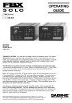
FBX-SOLO Model SL820
FBX-SOLO Model SM820
TABLE OF CONTENTS
• Front Panel Descriptions
5
• Back Panel Descriptions
6
• Applications for Use
8
• Before you Begin...
10
• Operating Instructions
13
• FBX Setup Instructions
14
• Trouble Shooting Tips
18
• Product Specifications
20
• Warranty & Cautions
22
QUICK START OPERATION
For best results, read all operating instructions
before using the FBX-SOLO (pages 10-19).
1
Patch in the SOLO where appropriate for your
model, and select the input/output level on the
back.
2
3
Adjust the Clip Level on the SOLO so at least
1 or 2 input LEDs light with your program input.
4
Continue raising the gain slowly until 7 FBX
filters are set, then reduce gain slightly.
With gain down on the mixer input channel, put
the SOLO in Active mode (green bypass
LED), then slowly raise the channel gain to the
point of feedback.
© 2006 Sabine, Inc.
CONGRATULATIONS!
You now have the state-of-the-art in feedback control. The Sabine FBX-SOLO gives you automatic
real-time feedback control for any channel of your
mix. In setup and during the performance, it gives
you more gain and increases the clarity of your
mains and monitors. It's the affordable solution to
feedback problems, perfect for wireless mics, monitors, acoustic/electric instruments, harmonica mics,
multi-mic locations like conference rooms and courthouses — wherever there's an open microphone.
The FBX-SOLO incorporates the latest in design
and digital signal processing technology. It automatically senses feedback in a sound system and
determines its pitch. It then places one of its eight
constant "Q" micro-filters on the resonating frequency and eliminates the feedback in typically less
than one second.
Special features of the SL820 and SM820:
•
New ultra fast Turbo Setup Mode grabs
feedback at very low levels.
•
The SL820 has 1/4" in/out connectors and
input/output level switches for any combination of ins and outs. The SL is for use
with acoustic/electric guitars and guitar
amplifiers, mixer insert points, powered
mixer patch points and high impedance
mics.
•
The SM820, with selectable phantom
power, has XLR in/out connectors for
use with microphones.
•
Both models offer standard FBX features
like switchable filter widths and lockable fixed filters.
•
New improved performance - 24 bit A/D
conversion, expanded dynamic range &
up to 8 FBX filters.
HOW CAN THE SOLO BE USED?
Assign a SOLO to any specific mixer channel. You
can also use the SM820 to connect a phantompowered mic to a non-phantom-powered mixer.
See SOLO Applications on page 8 & 9.
2
THE BEST FEEDBACK
CONTROLLER
Before the invention of the FBX, the most common
device for controlling feedback was the 31-band
graphic EQ. However, the FBX has three distinct
advantages. The most obvious is the FBX functions
automatically, even during the program. Another is
the FBX micro-filters are precisely placed while EQ
filters are fixed; FBX filters can be placed between
predetermined graphic filters. The difference: FBX
filters do not have to be as deep, so there is more
system gain. The final and most important advantage is that FBX micro-filters are ten times narrower
than 31-band EQ filters. FBX micro-filters return up
to 90 percent of the power removed by EQ filters.
Over the years, engineers stopped using 12-band
EQs in favor of the narrower-filter 31-band EQ for
controlling feedback. The FBX represents the next
step. An EQ would need more than 10,000 sliders
to be equivalent to your FBX. With the SOLO, your
monitors will finally sound loud enough, everyone in
the audience will understand each word, and the
mains will sound natural and transparent.
WHO NEEDS THE FBX?
Virtually every sound system will be improved with
the FBX. Small bands that do not have sound
technicians can now increase their monitor volumes
so they can hear themselves clearly and with full
fidelity, without worrying if the program is going to be
ruined by feedback.
Auditoriums and churches of all sizes will enjoy
reliable feedback control. Hotels and conference
centers around the world can offer meeting rooms
with sound systems that won’t howl during programs. The SOLO can be installed in theaters,
schools, sports arenas, courtrooms — anywhere
multiple microphones are used. It can also be used
for teleconferencing, intercoms or interactive remote classrooms.
WHY THE FBX?
The simple beauty of the FBX is its ability to quickly
and effectively eliminate feedback with narrower
filters than ever before possible. The FBX delivers
superior sound quality automatically.
3
A DIRECT HIT ON FEEDBACK! The FBX-SOLO
targets feedback without taking a big chunk out of
your sound. Tests prove that a single 1/3-octave EQ
slider pulled down 12 dB removes almost half the
power going to the speakers over a two-octave
range. And, as the illustration above shows, you
can't place a graphic EQ filter precisely on the
ringing frequency. When you pull down multiple
sliders in a normal setup (below), you end up with
giant holes in your sound. On the other hand, FBX
constant "Q" micro-filters are 10 times narrower you get back up to 90% of the power you lose with
a graphic EQ! That means more gain before feedback and no loss in sound quality.
FREQUENCY RESPONSE TEST: Full Set-Up FBX
vs. 1/3-Octave Graphic Equalizer. Test procedure: A
PA system was set up using a microphone, mixer, FBX,
power amp and two speakers. The system's gain was
raised until the FBX removed six feedback points. Next,
the FBX was replaced with a 1/3-octave graphic EQ.
The EQ was adjusted while the input was raised to the
same level achieved with the FBX. The frequency
response curves of each device were then plotted.
What this means to you: Doubling the cost of your
microphones, speakers and power amp probably would
not improve your system's frequency response as much
as replacing your EQ with an FBX for chasing feedback.
4
SL820 & SM820 FRONT PANELS
POWER
The On/Off power switch is a two-position push
button switch. The LEDs corresponding to all active
filters will blink on power-up.
ACTIVE/BYPASS
In Active mode, the unit controls feedback automatically. The two-color "BY" LED lights green
when the unit is in Active mode and lights red when
in Bypass mode. The mic preamp remains active in
Bypass mode; only the FBX function is bypassed.
DUAL-FUNCTION RESET
To reset only the dynamic filters, press and hold the
reset button. The LEDs will flash 3 times and then
the LEDs that indicate current Dynamic filter placement will shut off (fixed filter LEDs will remain on).
To reset ALL filters, hold the reset button until all
LEDs go off (approximately 7 flashes).
LOCK FIXED FILTERS
When the "Lock Fixed" button is pressed, its LED
will light to indicate that the FBX is in Lock Fixed
mode. Lock Fixed mode can be activated at any
time after system setup and will stay on until the
button is pressed again and the LED turns off. The
dynamic filters are not affected (see p.10 for details).
CLIP LEVEL ADJUST
The front panel clip level adjust knob has two
functions, and its use will depend on the setting of
the output switch on the back panel. When the
output is set to Unity, the Clip Level Adjust allows
you to set the optimal clip level for the input signal
— in order to optimize the dynamic range while
maintaining unity gain. Higher input levels will require the Clip Level Adjust to be turned counterclockwise to avoid distortion; lower input levels will
require the knob to be turned clockwise, to minimize noise.
5
Recommended setting of the Clip Level Adjust:
the clip LED should blink intermittently. NOTE: regardless of the Clip Level Adjust, setting Unity on the
back panel will maintain unity gain (no net gain or
loss of signal level).
When the back panel output is set to Line, the SOLO
acts as a preamplifier, and the Clip Level Adjust
knob becomes a gain control (see SL820 & SM820
Input Low/High Switch sections below).
SIGNAL LEVEL/TURBO INDICATOR
The LED ladder indicates the signal strength relative
to the SOLO's input level. Clip LED flashes independently
to indicate when the SOLO is in Turbo Setup mode.
FILTER ACTIVITY
When one of the unit’s constant "Q" filters is activated, the corresponding LED lights. A blinking LED
indicates the filter that was most recently activated.
All filter LEDs cycle to indicate Turbo Mode is about
to disengage. This occurs after the first dynamic filter
is set during the setup procedure.
FILTER WIDTH SWITCH
Switch to narrow 1/10-octave filters for music applications or to wider 1/5-octave filters for spoken word
applications. The change takes effect only on power
up. Selecting a new width has no effect unless you
power down and then power up again.
12 VOLT DC ADAPTOR
The FBX external power supply (single unit power
supply; model # SPSPOWR) is included with the
unit. Use of any other power supplies may cause
permanent damage to the unit and WILL VOID THE
WARRANTY.
SL820 BACK PANEL ONLY
INPUT LOW/HIGH SWITCH
Switch to Low for instrument or (high impedance
microphone) IN. Use with
low level inputs such as
piezo mic pick ups — this provides a 30 dB boost in
the FBX's input gain structure. Switch to High for
insert or line IN: use with high level output instruments
and signal processors.
6
OUTPUT UNITY/LINE SWITCH
Switch to Unity (level in = level out) for standard line,
insert, or guitar level applications. In the Unity setting,
the SL820 input level equals the output level, and the
front panel knob adjusts the clip level of the input
signal to the SOLO. Switch to Line (for line level out)
if your signal needs pre-amplification. In the Line
setting the front panel knob adjusts the output gain
between 0 and +35 dB (High IN); +30 to +65 dB (Low
IN).
INPUTS & OUTPUTS
The connector labeled IN/OUT serves as both the
unit's input (tip) and output (ring) when used with a
single TRS plug. When used with a Y-cord, use the
IN/OUT as the input and the OUT as the output (for
channel insert configurations).
SM820 ONLY BACK PANEL
OUTPUT LO/HI SWITCH
In the LO setting, the SM820
has unity gain (input = output); use LO for mic level. In
the HI setting, gain is adjustable between -15 dB
and +20 dB using the clip level adjust; use HI for line
level, or when you need to preamp the signal.
PHANTOM POWER ON/OFF SWITCH
The SM820 is set to "Phantom Power - OFF" at the
factory. If you wish to use phantom power, move the
switch to "ON." NOTE: The SM820 will not pass
phantom power from your mixer.
INPUT
The input accepts balanced XLR-3 (PIN 2 high)
plugs.
OUTPUT
Use balanced XLR-3 connectors (PIN 2 high) for
balanced mixer line inputs. NOTE: the output impedance of the SM820 is unbalanced.
7
APPLICATIONS
SL820: You can use the SL820 with
acoustic/electric guitars and guitar
amplifiers, mixer insert points, powered mixer patch points and high
impedance mics. Use the following
wiring diagrams as guides for setup:
SL820
NOTE: For Configurations 1-4, the output control on the
back panel of the SL820 may actually be set to either
Unity or Line. In the Unity setting the output level will
equal the input level, and, since the input level to the
SL820 in such a setup is already line level, the output will
be line level as well. When the output setting is switched
to Line, the front panel knob becomes a gain control,
and it is possible to add additional gain to your signal
path, if needed. Care should be taken in this situation
to avoid overdriving your mixer channel.
1. Mixer Channel Insert with TRS/TRS Cable
NOTE: Use a TRS
connector at both
ends of cable.
2. Mixer Channel Insert w/ Insert "Y" Cable
NOTE: Use a
TRS connector
only at the mixer
insert point.
3. Mixer Channel HI Impedance Mic on Line Input
8
4. Instrument IN for Amp
NOTE: An SL820 can be inserted at line level after
the mixer and before the power amp on smaller
systems.
Note for SM820: Use the SM820
with balanced microphones.
SM820
5. Mic Input to Mixer Line Input
6. Mic Input to Mixer Mic Input
9
BEFORE YOU BEGIN...
The FBX automatic feedback controller improves any
sound reinforcement system. By following these
simple instructions, you will be assured of the most
benefit from your FBX and sound system. The instructions presume that you are familiar with the
fundamentals of sound reinforcement. If any of the
terms are not clear, or if the system does not perform
as expected, contact your local Sabine dealer for
further information. Read on for a basic explanation of
FBX features you should understand before using
your FBX.
POWERING UP
When connecting the
power supply to the FBXSOLO, angle the connector down, then push
the connector up into the input gently, with the lip
facing up as shown. Do not force the connector into
or out of the FBX.
UNDERSTANDING FIXED & DYNAMIC FILTERS
The FBX has two types of constant “Q” filters: Fixed
and Dynamic. Both filters are placed the same way:
feedback is detected and the filter is placed just deep
enough to eliminate it. The difference between Fixed
and Dynamic comes after the filter is placed.
Fixed filters are set automatically during the initial
setup and remain on the initially detected feedback
frequency — they do not move. The system’s gain
before feedback is provided by the Fixed filters; i.e.,
increasing the number of Fixed filters increases the
system’s allowable gain before feedback. The FBX’s
Dynamic filters control intermittent feedback that
occurs during the program.
NOTE: Dynamic filters release only when necessary, i.e., after all filters have set, and a new
feedback frequency has been detected. These
filters will not "gradually release" as they might in
other feedback controllers — leaving you unprotected and at risk of feedback. Sabine's Dynamic
filters allow for adaptive, safe, continuous feedback control during the performance.
If Lock Fixed is not engaged, the Fixed filters will
control feedback during performance on their assigned frequencies (configured during setup). In10
creased activity at one of those frequencies may
cause the filter to go deeper (e.g.., deepen from -12
dB to -15 dB). Activating the Lock Fix function
prevents the Fixed filters from going deeper at their
assigned frequencies.
FIXED & DYNAMIC FILTER CONFIGURATION
The filters can be reconfigured easily from the factory
default setting (six fixed and two Dynamic) to any
combination of Fixed and Dynamic filters. For
example, the following procedure will set three filters
Fixed and five Dynamic:
1. Place the unit in Bypass mode.
2. Power down the SOLO.
3. While depressing the Reset button, power up
the unit.
4. Release the Reset button one second after the
Lock Fixed and Bypass LEDs turn on. The Filter
Indicator LEDs will now light in sequence.
5. When the third LED is lit, press the Reset button.
6. Notice that the first three LEDs flash three times
to verify that they are now the Fixed filters. Filters
which do not flash are Dynamic filters.
NOTE: The Fixed filters flash three times whenever the
FBX is powered up. Note: Resetting the number of fixed
versus dynamic filters also resets the noise gate to "off."
RESET OPTIONS
The Reset button has two functions: You can reset
all the FBX filters, or just the Dynamic filters. Press
and hold the Reset button and all filter LEDs will
begin flashing. To clear only the Dynamic filters,
press and hold the Reset button and release when
the Dynamic filter LEDs go off (after three flashes).
To clear all the filters, press and hold the Reset
button, but do not release until all the filters LEDs go
off (approximately 7 flashes). NOTE: A full reset is
recommended whenever you change speaker
or microphone positions. NOTE: Factory default
is 6 Fixed and 2 Dynamic filters, so if you reset
Dynamic filters, only those two lights will go out during
reset. A full reset also brings you into Turbo Mode.
WARNING: Do not reset all filters during the
program. This releases all the feedback you eliminated during setup. Use extreme caution when
resetting the Dynamic filters, because you may need
those filters at that moment during the show.
11
TURBO MODE SETUP
The FBX-SOLO incorporates Turbo Mode setup,
which is indicated by a flashing red Clip LED. This
lightning-quick setup feature cuts the time for FBX
filter initialization to just a few seconds.
NOTE: The SOLO is set in Turbo Mode at the factory
and automatically engages every time you reset
filters. The SOLO automatically returns to normal
program mode when the first dynamic filter is set, or
when you press the front panel Lock Fixed button. All
the filter LEDs will cycle to indicate that Turbo Mode
is about to disengage.
WARNING: Turbo Mode will cause distortion in
your audio program — it is for setup only. You
must follow the setup procedure outlined in the next
section, and do not talk or play program during
Turbo Setup Mode. Otherwise the FBX-SOLO will
clip, and filters may be set improperly. You’ll know
the FBX-SOLO is in Turbo Mode if the red Clip
LED flashes when no other signal level LEDs are
lit. You can manually override Turbo mode if necessary. If you are setting up in a noisy environment and
the SOLO is setting filters on that noise, press the
Lock Fixed button to exit Turbo mode, then press it
again to unlock the fixed filters. Follow the setup
procedure and allow the SOLO to place filters on
feedback. Press Lock Fixed when you are done to
lock those fixed filters.
MOBILE vs. STATIONARY MICROPHONES
One significant advantage offered by the Sabine
family of FBX Feedback Exterminator products is
their ability to adapt to changing acoustical relationships involving sound system components and various user applications. One major source of potential feedback problems arises in situations with
wireless microphones, when the user of the wireless
mic is moving around the stage/auditorium. As a
microphone moves in a sound space, with varying
degrees of proximity to the speakers and varying
acoustic responses, feedback frequencies may shift.
In such a situation, feedback-free mobility may be
more important a concern than maximum system
gain.
One method of setting FBX filters with mobile microphones is to turn a microphone on and walk around
to the various possible microphone locations. At the
12
same time, raise the system gain and set the FBX
filters one at a time.
In some situations, raising the number of dynamic
filters (versus fixed FBX filters) may allow a second
layer of defense against new feedback from new
locations. However, in many mobile microphone set
ups, fixed FBX filters will protect against feedback
across the range of microphone mobility.
OPERATING INSTRUCTIONS
SL820 SYSTEM INITIALIZING PROCEDURE
Choose the input level. Switch to LO for instrument
or microphone in (use with low level inputs such as
piezo mics); this provides a 30 dB boost in the FBX’s
input gain structure. Switch to HI for insert or line in
(use with high level output instruments and signal
processors).
Choose the output level. Switch to Unity when you
want level in to equal level out. In the Unity setting the
SL820 has a system gain of 1 (input = output level).
Switch to Line (for line level out) if your signal needs
pre-amplification. In the Line setting the gain is adjusted between 0 and +35 dB via the clip level adjust.
SM820 SYSTEM INITIALIZING PROCEDURE
Select Phantom Power ON/OFF. Your SM820 is
delivered from the factory with the phantom power
function disabled. If you wish to use phantom power,
you may enable the function by switching to “Phantom Power - ON” on the back panel. The majority of
low impedance balanced non-phantom-powered
mics are wired to ignore phantom power. Check your
microphone owner’s manual for verification to avoid
damage. The SM820 will not pass phantom power
from the mixer to your mic channel and is for
pre-fader channel input only.
SL820 & SM820 SETUP INSTRUCTIONS
Follow the steps on page 14 & 15 to obtain the
maximum gain before feedback without changing
the tonal quality of your program. Set up only one
SOLO at a time. The following instructions are for
using the SOLO on a channel insert. For use with
monitors, substitute monitor send and master monitor control for input channel level fader and mixer
master output. Be sure to turn off the mains when
initializing the SOLO in your monitor system.
13
FBX SETUP INSTRUCTIONS
1
Place the speakers and microphones in the positions where they
will be used during the program.
Avoid placing microphones directly
in front of speakers. If you are
using a graphic EQ, adjust it only
for the desired tonal qualities. DO
NOT NOTCH FOR FEEDBACK.
2
Set the mixer master output, all
channel level faders, and the
monitors to minimum.
OUTPUT, INPUT &
MONITOR LEVELS
3
Turn on the SOLO. Turn on the
mixer, any signal processing
equipment, and finally the power
amp. NOTE: Compressors in the
SOLO signal path should be off
during this procedure.
4
Press and hold the SOLO’s Reset
button (see page 8 for more details on the reset function) until
the LEDs stop flashing to clear
out all filters set previously.
NOTE: You are now in Turbo
Mode (see page 9 for details). Be
sure the “BY” LED is green (Active
mode) to indicate the SOLO is not
in Bypass mode (red).
5
Turn the SOLO’s clip level adjust
to the two o’clock position.
6
Set the mixer master output to a
nominal level.
MIXER MASTER
14
7
Slowly raise the input
channel level fader for
the channel being set
until feedback occurs.
The SOLO should
quickly remove the feedback.
CHANNEL
INPUT
LEVEL
FIRST FEEDBACK
TONE
The first Filter LED will then blink
to indicate a filter has been set.
8
Keep raising the level slowly
until all Fixed Filters and one
Dynamic filter is set. Turbo Setup
Mode goes OFF automatically
when the first Dynamic filter is
initialized. Any un-initialized Dynamic filters will be set later if
feedback occurs during the program.
FEEDBACK
TONES
CHANNEL INPUT
LEVEL
You can limit the total number of
filters in use by pressing the
Lock Fixed button before setup
is automatically ended.
Now lower the channel level fader
slightly so that the system is not
on the verge of another feedback
point. This is the maximum volume level that the FBX-SOLO
will be able to provide. Higher
levels will cause uncontrollable
feedback.
9
CHANNEL INPUT
LEVEL
Finally, during sound check, adjust the Clip Level Adjust so that
the red Clip LED blinks intermittently, as you would adjust the
recording level of a tape recorder.
The unit will clip and distort the
program if the Clip Level Adjust is
set too high. If it is set too low,
the signal-to-noise ratio will degrade and the system may hiss.
IMPORTANT: Make sure Turbo mode is OFF —
Clip LED NOT flashing!
15
HOW TO USE THE LOCK FIXED FEATURE
In certain situations the FBX may mistake music for
feedback and drive the fixed filters deeper than
necessary, like in a church with a pipe organ or during
a performance with a great deal of intentional sustained electric guitar feedback. You may prevent the
fixed filters from deepening beyond their initial depth
by pressing the Lock Fixed button on the front panel
AFTER setting the fixed filters as described previously. The Lock Fixed LED will light to indicate that
the FBX is in Lock Fixed mode. The fixed filters will
stay locked until you press the Lock Fixed button
again. The dynamic filters are not affected. In almost
every situation, it is best to lock the fixed filters
right after the initial setup.
LIMITING TOTAL NUMBER OF ACTIVE FILTERS
You may choose to limit the total number of active
filters for each application by using the Lock Fixed
button. For example, if you wish to use only three
fixed and one dynamic filter, set the FBX so there are
seven fixed and one dynamic filter. Then during the
setup procedure, simply press the Lock Fixed button
after setting the first three fixed filters. The remaining
four fixed filters will be locked in their zero position.
SELECTING FILTER WIDTH
If the SOLO is to be used for a music application, 1/10octave filters are most effective. However, in spoken
word applications, such as lectures or teleconferencing, the wider 1/5-octave filters are recommended.
Select the filter width using the switch on the SOLO
back panel. The change takes effect only on powerup. Selecting a new width has no effect unless you
power down and then power up again.
ENGAGING THE NOISE GATE
One outstanding feature of your FBX-SOLO is a userselectable noise gate. A noise gate is especially
useful in systems that have a number of open microphones, such as courtrooms, conference rooms, or
parliament buildings. Gating microphones greatly reduces the number of possible feedback points in the
room and allows for more system gain.
The level at which the noise gate turns on and off is
called the threshold. If the level coming into the gate
is greater than the threshold, the noise gate opens,
16
and the mic is turned
on. If it is less than
the threshold, the
noise gate closes,
and the mic is turned
off.
You can adjust your
SOLO to four different
threshold levels (see
diagram above), or
turn it off. To select
the threshold, power down the SOLO. Hold in the
Lock Fixed button, power up the SOLO and release
it one second after the Lock Fixed and Bypass LEDs
turn on. The clip level LEDs will light in sequence.
Select the threshold level by pressing the Lock Fixed
button again when the clip LED lights at the corresponding threshold level. The noise gate is now
enabled, indicated by a flashing level LED on powerup. Pressing the Lock Fixed button with no clip
LEDs lighted turns off the noise gate. If no lights
flash on power-up, the noise gate is not engaged. When the SOLO's noise gate is enabled, it
will not become engaged until after you've set all fixed
filters and one dynamic filter (if the SOLO is configured
for any). Note: Resetting the number of fixed versus
dynamic filters also resets the noise gate to "off."
USING SABINE'S OPTIONAL SOLO ACCESSORIES
1-U rack tray (model # SL6RACK): An optional 1U rack tray holds up to six SOLOs (and/or Sabine's
SDA102 digital delays). Mount the SL820s, SM820s,
or a combination of both side by side on the tray. Use
only Sabine supplied screws; use of any other screws
may damage the SOLO and void the warranty.
IMPORTANT OPERATING CONSIDERATIONS
MEMORY: The FBX stores the positions and depths
of the filters in nonvolatile internal memory when the
unit is turned off or during a power failure. The unit will
return all filters to their previous frequencies and
depths when it is turned back on.
BYPASS MODE: Placing the FBX-SOLO in bypass
mode only shuts down the FBX function; the microphone preamp still functions when the unit is in
bypass mode. The SOLO will not pass signal if the
power is off in either active or bypass mode.
17
RESETTING THE FILTERS: You must reset the
FBX if the microphones or speakers are moved
significantly.
To reset ALL filters: Press and hold the reset
button until the filter LEDs flash about 7 times, or
until all filter LEDs turn off.
To reset only the dynamic filters: Press and hold
the reset button for 3 flashes and let go. The LEDs
that indicate current dynamic filter placement will be
off, and the fixed filter LEDs will remain on.
TROUBLESHOOTING TIPS
Q. Can I patch the SOLO SL820 after the mixer and
before the power amp?
A. Yes, but only in cases where just eight feedback
filters are needed, such as on the monitors
alone. Eight FBX filters may not always provide
enough gain before feedback for your entire mix.
Q. Sometimes I don't get enough gain before feedback. Why?
A. Gain before feedback is determined by the number of fixed filters you set; increasing the number
of fixed filters during setup increases the system's
gain before feedback. Fixed filters are set
automatically during the initial setup and remain
on the initially detected feedback tone -- they do
not move. You can reconfigure the filters from
the factory default setting (six fixed and two
dynamic) to any combination of fixed and dynamic filters. Review the procedure on page 10,
UNDERSTANDING FIXED AND DYNAMIC FILTERS of this operating guide.
Q. The Clip Level LEDs do not light. The unit will not
catch feedback. Why?
A. The unit is not in the signal path. Check the
connections.
Q. Why does one of the Filter Activity LEDs blink?
A. The last filter to be automatically updated blinks.
During normal operation, the blinking will move
from filter to filter as the SOLO finds new feedback points. This gives the user a visual confirmation that the unit is functioning properly.
18
Q. Why does my SOLO set filters when music is
played through it?
A. Make sure the FBX’s Turbo Mode has been
turned off before you program. Check the signal
level ladder. If the red Clip LED lights with no
other signal level LEDs lit, the FBX-SOLO is still
in Turbo Mode. Turbo Mode turns off automatically after the first dynamic filter is set, or you can
turn it off manually by pressing the Lock Fixed
button. Turbo Mode sets filters very quickly —
without analyzing the signal — and may not
distinguish feedback from music or audio signal.
Q. Why would the FBX cause a noticeable hum?
A. It may hum if the system is improperly grounded.
Check for bad grounds.
Q. Why does my system sound thin and muffled?
A. Place the SOLO in Bypass Mode. If the system
still sounds thin, your problem is probably with
improper use of a graphic EQ. If the problem
exists only with the SOLO in Active mode, verify
the clip level setting, reinitialize the system and
lock the fixed filters.
Q. With the SL820 in the insert point, I hear no
audio. Why?
A. Your insert point may be wired opposite to the
SOLO. Try reversing the tip and ring (in and out)
of your Y-cord. If you are using a single TRS
cable, you will have to reconfigure one end of it
to conform to your mixer insert point.
Q. Will the SOLO eliminate feedback in both mains
and monitors?
A. Yes, but for maximum gain you should set as
many fixed filters as possible on the system with
the most feedback problems. Choose which
system is more likely to have feedback, and
follow the system initializing procedure for either
mains or monitors. During program, the dynamic filters will control feedback for both mains
and monitors if they are in use, but only on the
input channel the SOLO is patched into.
Q. The channel I have the SOLO in seems noisy.
What can I do?
A. If the noise floor is too high, you need to readjust
the gain structure of that channel. Follow the
SOLO initialization instructions in this guide.
19
PRODUCT SPECIFICATIONS
FILTERS
Eight independent digital notch filters controlled
automatically from 40 Hz to 20 KHz
Filter width: 1/10 octave, typical, or 1/5-oct.
selectable; constant "Q"
Filter depth: DSP controlled, variable to -50 dB
Resolution: 1/50th octave
Time required to find and eliminate feedback:
0.4 sec., typical @ 1 KHz
Total number of combined filters active: User
selectable, from 1-8
Number of Dynamic vs. Fixed filters: User
selectable
Last configuration stored in memory
INPUT/OUTPUT - SL820 ONLY
I/O Connectors: 1/4" TRS; tip = input, ring =
output, sleeve = ground
Input Impedance: Unbalanced >1 meg Ohm
Output Impedance: Unbalanced 10 Ohms
nominal; Maximum load 2K Ohms
Maximum Input/Output Level at lowest gain:
+20 dBV
Gain Range (with line out selected): 0 to +35 dB
(high in), +30 to +65 dB (low in)
Input to Output Gain @ unity setting: +/- 0.5 dBV
Bypass: Digital
INPUT/OUTPUT - SM820 ONLY
I/O Connectors: XLR-3 PIN 2 high Balanced
Input Impedance: 1K Ohm nominal
Output Impedance: Unbalanced 10 Ohms
nominal; Maximum load 2K Ohms
Maximum Input/Output Level at lowest gain: -10
dBV**
Gain Range: -15 to +20 dB (at high output)
Input to Output Gain @ unity setting: +/- 0.5 dBV
Bypass: Digital
EIN: -105 dBm @ 150 Ohms, 20 Hz - 20 KHz or
better
Phantom Power: 48V switch selectable
20
PERFORMANCE***
Frequency Response: < +0.75 dB, 20 Hz to 20
KHz
Signal to Noise Ratio: >94 dB typical
Total Harmonic Distortion: <0.01% @ 1 KHz @
+15 dBV
Dynamic Range: >100 dB
NOISE GATE
Attack Time: Fixed (400 mS)
Threshold: Selectable (-24 dB, -36 dB, -48 dB, -60
dB)
POWER SUPPLY
8-20 VDC @ 400 mA
DIMENSIONS
1-U height, 1/6-RU width; 2.78 x 1.65 x 5.5 in. (6.95
x 4.13 x 13.75 cm)
WEIGHT
9 oz. (0.26 kg)
OPTIONS
SL6RACK Rack Tray (holds up to six units)
*Below approximately 200 Hz the feedback filters become
slightly wider to increase the capture speed of feedback and
rumble at these low frequencies.
**Note: Inputs may be balanced or unbalanced.
***Tests performed using an Audio Precision System One
model 322 or equal.
SPECIFICATIONS SUBJECT TO CHANGE WITHOUT NOTICE.
21
CAUTION
EXPOSURE TO EXTREMELY HIGH NOISE LEVELS MAY CAUSE A PERMANENT HEARING
LOSS. INDIVIDUALS VARY CONSIDERABLY IN SUSCEPTIBILITY TO NOISE INDUCED HEARING LOSS, BUT NEARLY EVERYONE WILL LOSE SOME HEARING IF EXPOSED TO SUFFICIENTLY INTENSE NOISE FOR A SUFFICIENT TIME. THE U.S. GOVERNMENT'S OCCUPATIONAL SAFETY AND HEALTH ADMINISTRATION (OSHA) HAS SPECIFIED THE FOLLOWING
PERMISSIBLE NOISE LEVEL EXPOSURES:
DURATION/DAY
IN HOURS
8
6
4
3
2
SOUND LEVEL IN dBA,
SLOW RESPONSE
90
92
95
97
100
DURATION/DAY
IN HOURS
1-1/2
1
1/2
1/4 or less
SOUND LEVEL IN dBA,
SLOW RESPONSE
102
105
110
115
ACCORDING TO OSHA, ANY EXPOSURE IN EXCESS OF THE ABOVE PERMISSIBLE LIMITS
COULD RESULT IN HEARING LOSS. EAR PLUGS OR PROTECTORS IN THE EAR CANALS OR
OVER THE EARS MUST BE WORN WHEN OPERATING THIS DEVICE IN ORDER TO PREVENT
A PERMANENT HEARING LOSS. IF EXPOSURE IS IN EXCESS OF THE LIMITS AS SET FORTH
ABOVE, TO ENSURE AGAINST POTENTIALLY DANGEROUS EXPOSURE TO HIGH SOUND
PRESSURE LEVELS, IT IS RECOMMENDED THAT ALL PERSONS EXPOSED TO EQUIPMENT
CAPABLE OF PRODUCING HIGH SOUND PRESSURE LEVELS SUCH AS THIS DEVICE BE
PROTECTED BY HEARING PROTECTORS WHILE THIS UNIT IS IN OPERATION.
1.
2.
3.
4.
5.
6.
7.
8.
9.
10.
11.
12.
13.
14.
15.
Read all safety and operating instructions before using this product.
All safety and operating instructions should be retained for future reference.
Obey all cautions in the operating instructions and on the unit.
All operating instructions should be followed.
Use only shielded audio and data cables.
This product should not be used in the presence of moisture or rain, or near any water, i.e., a
bathtub, sink, swimming pool, wet basement, etc.
This product should be located so that its position does not interfere with proper ventilation. Do
not use in direct sunlight. Do not place flat against a wall or in a built-in enclosure that will impede
the flow of cooling air.
This product should not be placed near a source of heat such as a stove or radiator.
Connect only to a power supply of the type marked on the unit adjacent to the power entry module.
Never break off the ground pin on the power supply cord.
Power supply cords should always be handled carefully. Never walk or place equipment on power
supply cords. Periodically check cords for cuts or signs of stress, especially at the plug and the
point where the cord exits the unit.
The power supply cord should be unplugged when the unit is to be unused for long periods of time.
Care should be taken so that objects do not fall and liquids are not spilled into the unit through the
ventilation holes or any other openings.
This unit should be checked by a qualified service technician if:
A. The power supply cord or plug has been damaged.
B. Anything has fallen or been spilled into the unit.
C. The unit does not operate correctly.
D. The unit has been dropped or the enclosure damaged.
The user should not attempt to service this equipment. All service work should be done by a
qualified service technician.
OSHA 2201; 1995 revised.
FCC STATEMENT
Warning: Changes or modifications to this unit not expressly approved by the party responsible for
compliance could void the user's authority to operate the equipment.
This device complies with Part 15, Class B, of the FCC Rules. Operation is subject to the following
conditions: (1) This device may not cause harmful interference; and (2) This device must accept any
interference received, including interference that may cause undesired operation.
NOTE: This equipment has been tested and found to comply with the limits for a Class B digital
device, pursuant to Part 15 of the FCC Rules. These limits are designed to provide reasonable
protection against harmful interference in a residential installation. This equipment generates, uses,
and can radiate radio frequency energy and, if not installed and used in accordance with the instructions, may cause harmful interference to radio communications. However, there is no guarantee
that interference will not occur in a particular installation. If this equipment does cause harmful
interference to radio or television reception, which can be determined by turning the equipment off
and on, the user is encouraged to try to correct the interference by one or more of the following
measures:
• Reorient or relocate the receiving antenna.
• Increase the separation between the equipment and receiver.
• Connect the equipment into an outlet on a circuit different from that to which the receiver is
connected.
• Consult the dealer or an experienced radio TV technician for help.
This digital apparatus does not exceed the Class B limits for radio noise emissions from digital
apparatus set out in the Radio Interference Regulations of the Canadian Department of Communications.
Le present appareil numerique n'emet pas de bruits radioelectriques depassant les limites applicables
aux appareils numeriques de la class B prescrites dans le Reglement sur le brouillage radioelectrique
edicte par le ministere des Communications du Canada.
Japanese EMI Statement:
Only when used with the following Sabine-supplied power modules:
AD 1280-100
AD 1280-120
AD 1280-230
AD 1280-240A
AD 1280-240U
22
ONE-YEAR LIMITED WARRANTY:
THIS LIMITED WARRANTY VALID ONLY WHEN PURCHASED AND REGISTERED IN THE
UNITED STATES OR CANADA. ALL EXPORTED PRODUCTS ARE SUBJECT TO WARRANTY
AND SERVICES TO BE SPECIFIED AND PROVIDED BY THE AUTHORIZED DISTRIBUTOR FOR
EACH COUNTRY.
Ces clauses de garantie ne sont vaiables qu’aux Etats-Unis et au Canada. Dans tous les autres pays,
les clauses de garantie et de maintenance sont fixees par le distributeur national et assuree par lui
selon la legislation en vigueur.
Diese Garantie ist nur in den USA and Kanada gultig. Alle Export-Produkte sind der Garantie und dem
Service des Importeurs des jewelligen Landes untervorfen.
Esta garantia es valida solamente cuando el producto es comprado en E.U. continentales o en Canada.
Todos los productos que sean comprados en el extranjero, estan sujetos a las garantias y servicio que
cada distribuidor autorizado determine y otrezca en los diterentes paises.
ONE-YEAR LIMITED WARRANTY/REMEDY
SABINE, INC. (“SABINE”) warrants this product to be free from defects in material and workmanship
for a period of one (1) year from date of purchase PROVlDED, however, that this limited warranty is
extended only to the original retail purchaser and is subject to the conditions, exclusions and limitations hereinafter set forth:
CONDITIONS, EXCLUSIONS AND LIMITATIONS OF LIMITED WARRANTIES
These limited warranties shall be void and of no effect if:
a. The first purchase of the product is for the purpose of resale; or
b. The original retail purchase is not made from an AUTHORIZED SABINE DEALER; or
c. The product has been damaged by accident or unreasonable use, neglect, improper service or
maintenance, or other causes not arising out of defects in material or workmanship; or
d. The serial number affixed to the product is altered, defaced or removed; or
e. The power supply grounding pin is removed or otherwise defeated. In the event of a defect in
material and/or workmanship covered by this limited warranty, Sabine will repair the defect in material
or workmanship or replace the product, at Sabine’s option; and provided, however, that, in any case,
all costs of shipping, if necessary, are paid by you, the purchaser.
THE WARRANTY REGISTRATION CARD SHOULD BE ACCURATELY COMPLETED, MAILED TO
AND RECEIVED BY SABINE WITHIN FOURTEEN (14) DAYS FROM THE DATE OF YOUR
PURCHASE.
In order to obtain service under these warranties, you must:
a. Bring the defective item to any AUTHORlZED SABlNE DEALER and present therewith the ORIGINAL PROOF OF PURCHASE supplied to you by the AUTHORIZED SABINE DEALER in connection
with your purchase from him of this product. If the DEALER is unable to provide the necessary
warranty service, you will be directed to the nearest other SABINE AUTHORIZED DEALER which can
provide such service. OR
b. Call Sabine for a RETURN AUTHORIZATION NUMBER and ship the defective item, prepaid, to:
SABINE, INC. 13301 HIGHWAY 441
ALACHUA, FL 32615-8544 USA
including therewith a complete, detailed description of the problem, together with a legible copy of the
original PROOF OF PURCHASE and a complete return address. Upon Sabine’s receipt of these
items:
If the defect is remedial under the limited warranties and the other terms and conditions expressed
have been complied with, Sabine will provide the necessary warranty service to repair or replace the
product and will return it, FREIGHT COLLECT, to you, the purchaser.
Sabine’s liability to the purchaser for damages from any cause whatsoever and regardless of the form
of action, including negligence, is limited to the actual damages up to the greater of $500.00 or an
amount equal to the purchase price of the product that caused the damage or that is the subject of or
is directly related to the cause of action. Such purchase price will be that in effect for the specific
product when the cause of action arose. This limitation of liability will not apply to claims for personal
injury or damage to real property or tangible personal property allegedly caused by Sabine’s negligence. Sabine does not assume liability for personal injury or property damage arising out of or
caused by a non-Sabine alteration or attachment, nor does Sabine assume any responsibility for
damage to interconnected non-Sabine equipment that may result from the normal functioning and
maintenance of the Sabine equipment.
UNDER NO CIRCUMSTANCES WILL SABINE BE LIABLE FOR ANY LOST PROFITS, LOST
SAVINGS, ANY INCIDENTAL DAMAGES OR ANY CONSEQUENTIAL DAMAGES ARISING OUT OF
THE USE OR INABILITY TO USE THE PRODUCT, EVEN IF SABINE HAS BEEN ADVISED OF THE
POSSIBILITY OF SUCH DAMAGES.
THESE LIMITED WARRANTIES ARE IN LIEU OF ANY AND ALL WARRANTIES, EXPRESS OR
IMPLIED, INCLUDING BUT NOT LIMITED TO, THE IMPLIED WARRANTIES OF MERCHANTABILITY AND FITNESS FOR A PARTICULAR USE; PROVIDED, HOWEVER, THAT IF THE OTHER
TERMS AND CONDITIONS NECESSARY TO THE EXISTENCE OF THE EXPRESS LIMITED
WARRANTIES, AS HEREINABOVE STATED, HAVE BEEN COMPLIED WITH, IMPLIED WARRANTIES ARE NOT DISCLAIMED DURING THE APPLICABLE ONE-YEAR PERIOD FROM DATE OF
PURCHASE OF THIS PRODUCT.
SOME STATES DO NOT ALLOW LIMITATION ON HOW LONG AN IMPLIED WARRANTY LASTS,
OR THE EXCLUSION OR LIMITATION OF INCIDENTAL OR CONSEQUENTIAL DAMAGES, SO THE
ABOVE LIMITATIONS OR EXCLUSIONS MAY NOT APPLY TO YOU. THESE LIMITED WARRANTIES GIVE YOU SPECIFIC LEGAL RIGHTS, AND YOU MAY ALSO HAVE OTHER RIGHTS WHICH
MAY VARY FROM STATE TO STATE.
THESE LIMITED WARRANTIES ARE THE ONLY EXPRESS WARRANTIES ON THIS PRODUCT,
AND NO OTHER STATEMENT, REPRESENTATION, WARRANTY OR AGREEMENT BY ANY
PERSON SHALL BE VALID OR BINDING UPON SABINE.
In the event of any modification or disclaimer of express or implied warranties, or any limitation of
remedies, contained herein conflicts with applicable law, then such modification, disclaimer or limitation, as the case may be, shall be deemed to be modified to the extent necessary to comply with such
law.
Your remedies for breach of these warranties are limited to those remedies provided herein, and
Sabine gives this limited warranty only with respect to equipment purchased in the United States of
America.
INSTRUCTIONS-WARRANTY REGISTRATION CARD
1. Mail the completed WARRANTY REGISTRATION CARD to:
SABINE, INC. 13301 HighWAY 441
ALACHUA, FL 32615-8544 USA
a. Keep the PROOF OF PURCHASE. In the event warranty service is required during the warranty
period, you will need this document. There will be no identification card issued by Sabine, Inc.
2. IMPORTANCE OF WARRANTY REGISTRATION CARDS AND NOTIFICATION OF CHANGES
OF ADDRESS:
a. Completion and mailing of WARRANTY REGISTRATION CARDS - Should notification become
necessary for any condition that may require correction, the REGISTRATION CARD will help ensure
that you are contacted and properly notified.
b. Notice of address changes - If you move from the address shown on the WARRANTY REGISTRATION CARD, you should notify Sabine of the change of address so as to facilitate your receipt of any
bulletins or other forms of notification which may become necessary in connection with any condition
that may require dissemination of information or correction.
3. You may contact Sabine directly by telephoning (386) 418-2000.
4. Please have the Sabine product name and serial number available when communicating with
Sabine Customer Service.
23
REGISTER YOUR SABINE
PRODUCT ONLINE AT
WWW.SABINE.COM
Manufactured by: Sabine, Inc.
13301 NW US Highway 441
Alachua, Florida 32615-8544 USA
+USA (386) 418-2000 • Fax: +USA (386) 418-2001
www.Sabine.com
FBX® and FBX Feedback Exterminator® are registered trademarks of Sabine, Inc., and are the brand names of its line of
automatic feedback controllers. Covered by U.S. Patent No.
5,245,665, Australian Patent No. 653,736, Canadian Patent No.
2,066,624-2, German Patent No. 69118486.0, and British Patent
No. 0486679. Other patents pending.
© 2006 Sabine, Inc.
LITSOLO-OP-060210.pmd - rr