1
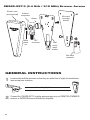
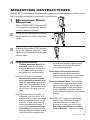
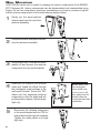
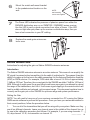
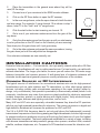
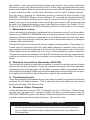
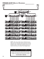
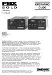
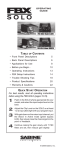
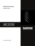
2.4 GHz / 915 MHz Smart Spectrum®
Extension Antenna Kit
SWASS-EXT-3-M1 / SWASS-EXT-3-M9
Operating Guide
This guide is for use with
SWM7000-M1 Series models:
SWM6000-M9 Series models:
SW71-R-M1
SW61-R-M9
SW72-R-M1
SW62-R-M9
SW72-NDR-M1
SW62-NDR-M9
SWA6SS-M1
SWA6SS-M9
SWASS-EXT-3 benefits
• Wall mount or mic-stand mount
• Straight and right angle TNC connectors
• 130 degree reception pattern
• Variable gain, from 0 to +44 dB
• Wood-tone finish
• Phantom-powered from either the receiver or
the distribution amp; Power LED indicator
Included with the SWASS-EXT-3
• One pair of antennas, each with mic
stand mounts attached
• Two European mic stand adaptor inserts
• Four straight TNC male crimp connectors
• Two right angle TNC male to female
connectors
• Operating Guide
OVERVIEW
The SWASS-EXT-3-M1 Antenna Extension Kit is designed for use with Sabine SWM7000
2.4 GHz and the SWASS-EXT-3-M9 is for use with the SWM6000 915 MHz. wireless microphone receivers and antenna distribution amplifiers. Both of the SWASS-EXT-3 units
allow for optimal placement of external antennas for maximum wireless performance. One
SWASS-EXT-3 kit can accommodate up to 70 receiver channels. (See block diagram
detail on page 10).
Antenna Placement
Extension antennas should be placed in an open area within visual range of the intended
transmitter locations. Note that the range of a True Mobility transmitter is about 100 meters, but that structural objects can reduce that range.
Cautions
• Since the installation of the antennas influences the operating efficiency of the receiver,
the most important rule is to minimize the distance between receiving antenna and
transmitter for better reception and performance. Make sure the antennas can “see”
the transmitter.
• Keep the system away from electrical-noise sources (electric motors, refrigerators, arc
welders, etc.). Place the SWM7000/SWM6000 receiver or SWA6SS Antenna Distribution Amplifier at least 1.5 meters above floor level. Keep all transmitters at least 3
meters away from a receiver antenna.
Antenna Cabling & Cable Loss
While an extension antenna affords the opportunity to increase the distance from transmitter to receiver, there is a loss of signal in the interconnecting cable that limits that distance. The maximum connection length is determined by the type of cable used, and the degree
of signal attenuation acceptable. Let’s presume that an acceptable degree of loss over the total cable run is 6 dB. Without
external signal boosts, the different cables shown in the table would then allow maximum
lengths ranging from less than 4 M (RG-58) to 24 M (RG8/U). Thus, for a passive extension antenna, your choices are to limit the cable run, or increase your budget and buy the
more expensive, thicker cable.
Coaxial Cable Attenuation Table
Cable
Type
Belden #
Insulation
Center
Condctor
10 Meter
Attenuation (dB)
2.4 GHz
915 MHz
Maximum Practical Distance
using SWASS-EXT set
for +22 dB boost (meters)
2.4 GHz
915 MHz
Connector
Type
9203
Polyethylene
#20 Stranded
-16.29
-16.29 -6.5
14
TNC
14 35
TNC
RG58/AU
9311
Foam
Polyethylene
#20 Stranded
-11.10 -4.7
-11.10
20
TNC
20 47
TNC
RG212/U
9861
Polyethylene
#15.5 solid, silver plated
-6.11
-6.11 -3.0
36
N
36 73
N
#10 solid
-2.50
-2.50 -1.3
88
N
88 170
N
#18 solid,
silver plated
-6.54
-6.54 -4.0
34
TNC
34 55
TNC
RG58
RG8/U
9913
Semi-solid Polyethylene
RG142
83242
Teflon
2
Fortunately, Sabine’s SWASS-EXT-3 Active Extension Antenna offers a far better, more
cost-effective solution, due to its built-in active 18 dB signal boost. In the case of low-cost
RG-58 cable, adding an SWASS-EXT-3 to your setup increases the acceptable maximum
cable run by more than 4 times, to 14 meters. With RG-8 cable, the maximum length is
extended to 88 meters! Power for the Extension Antenna is delivered from any Sabine SWM7000/SWM6000
series receiver or SWA6SS Antenna Distribution Amplifier.
An additional advantage of using Sabine’s SWASS-EXT-3 Extension Antenna stems from
its more focused, directional nature. Sabine receiver’s coaxial dipole antennas (standard
equipment that mount directly on the front or rear panels of the receiver or SWA6SS) are
more omni directional in nature. In contrast, the Sabine’s Extension Antenna is sensitive
to RF reception in a 180-degree arc in front of its mounted position. It extends sensitivity
to the front and off-axis side locations as it increases rear RF rejection.
The multiple functions (relocation of antenna, boost of signal, directional sensitivity) of
Sabine’s Extension Antenna mean there are many applications in which its addition to your
system can greatly enhance performance. Here’s a partial list of such applications:
1. Antenna repositioning. Provides solutions when receiver placement options are
limited or challenging. Sabine’s Extension Antenna’s multiple mounting options allow
higher placement (wall mount or microphone stand mount).
2. Barriers interrupting transmission. Any time a barrier interferes with transmission
and reception, Sabine’s SWASS-EXT-3 can be mounted on the transmitter side of the
barrier with cable connections made on the receiver side. The most common situation of this nature would arise when receiver and transmitter are located in separate
rooms.
3. Expanded or directional sensitivity required. Sabine’s Extension Antenna picks up
in a 180-degree arc, focused towards the front. Reception in this arc is enhanced.
4. Rear RF rejection required. Because Sabine’s Extension Antenna is less sensitive
to signals received from the rear, it can be positioned to reject any such directional RF
interference.
6. Variable Gain. This model allows for continuously variable gain settings from 0 to +44
dB. There should be a minimum of 12dB of cable loss before the antenna gain is set
to the maximum gain setting of +44 dB. If maximum gain is set with less than 12dB
of cable loss the receiver front end may get overloaded. Refer to the chart at left and
use maximum gain only for extending the maximum practical distance of the cable you
are using. See page 7 for instructions on setting the antenna gain.
LIT-SWASS-EXT-3-OP-080625.indd
LIT-SWASS-EXT-3-OP-092508.indd
3
© 2008
2009 Sabine, Inc
5. Extended operational range. Given a potential maximum cable length of almost 90
meters from Extension Antenna to receiver, Sabine’s SWASS-EXT-3 allows more options for extending the distance between transmitter and receiver. Consider that RF
signal strength through air is diminished by the square of the distance (twice as far
away = ¼ the signal strength), while signal loss through cable is (roughly) inversely
proportional (twice as far away = ½ the signal). That means you can use an extension
antenna to replace transmission-through-air with transmission-through-cable, to help
minimize signal loss.
SWASS-EXT-3 (2.4 GHz / 915 MHz) External Antenna
Exterior case
(wood-grained)
Antenna
component
Mic stand
mounting
bracket
Spacer
White
plastic
nut
TNC
connector
Wall
mount
metal
bracket
Mic stand
connector
General Instructions
1
Locate and install the antennas so that they are within line-of-sight of intended wireless microphone locations.
Line-of-sight path
2
4
Connect the SWASS-EXT-3 to either antenna input on your SWM7000 /SWM6000
receiver or SWA6SS Antenna Distribution Amplifier.
Mounting Instructions
SWASS-EXT-3 Antennas can be permanently mounted on wall surfaces, or affixed to the
top of microphone stands for convenient re-positioning.
1
Microphone Stand
Mounting
Attach SWASS-EXT-3 Antenna Kits
to microphone stands and position
stands in desired locations.
Gently pry the wood-grained exterior
case from the rest of the antenna assembly.
3
Attach antenna cable to TNC connector on the antenna assembly. Hand
tighten only. Reattach the wood-grain
exterior case
4
Placing Extension Antennas Position anntennas about 10-15
feet apart. When you mount the
extension antennas on a stand or on
a wall, make sure the short side of
the triangle is up, as shown above. In order for the system to be effective,
both extension antennas should
be in a good pickup position at all
times but separated by about ten or
fifteen feet if the antennas are within
100 or so feet. Separate them about
20 to 25 feet in very large rooms or
fields. If you put the antennas too far apart, i.e.,
at opposite ends of the room, or in
separate rooms, to improve coverage,
diversity is defeated and you will get
dropouts. In other words, diversity
is more important that coverage. If
you mount the extension antennas
in the ceiling, the antennas metallic
backplane must be orientated parallel
to the floor and the antennas must
not be blocked by pillars, lights or similar
obstructions. Aim the hole in the plastic
cover toward the podium.
Do not daisy-chain extension antennas
together in series. Receivers and the
antenna distribution amp are only designed
to use one left and one right antenna. Extension Antenna Cables: Use coax cable
to connect the extension antennas to the
receiver or to the ADA. See the chart on
the previous page for cable specifications. Use the SWATNC-N step-down cable to
connect thicker RG8 cables to the extension
antenna.
The SWASS-EXT-3 extension antennas add
between 0 and 44dB signal strength to
overcome cable loss. See page 7 for
instructions on setting the antenna gain.
Bad crimp connections are a common
cause of dropouts. Check them carefully!
LIT-SWASS-EXT-3-OP-080625.indd
LIT-SWASS-EXT-3-OP-092508.indd
5
© 2009
2008 Sabine, Inc
2
Wall Mounting
CAUTION: Be careful not to scratch or damage the interior components of the SWASSEXT-3 Antenna Kit. Interior components can be disassembled and reassembled using
fingers. Do not use metal pliers, wrenches, screwdrivers or knives to unscrew or tighten
interior antenna components to the metal antenna bracket frame.
1
Gently pry the wood-grained
exterior case from the rest of the
antenna assembly.
2
Unscrew the black microphone mount
from the antenna assembly.
3
Using fingers only, unscrew the white
plastic nut and remove the antenna
component from the metal bracket.
4
Attach the TNC elbow to your antenna
cable and thread the elbow through
the rectangular metal cutaway in the
wall-mount bracket. Screw the TNC
elbow onto the separated antenna
component so that the cable end will
go through the cutaway. Tighten finger
tight only.
5
6
Reconnect the antenna component
to the metal bracket with the TNC elbow positioned through the cutaway.
Tighten the white plastic nut finger
tight only.
NOTE: Make sure
the rectangular
silver shield case
(shield-w2antl) will
face away from the
bracket when the
component has been
remounted.
6
7
8
Mount the metal wall-mount bracket
to the predetermined location on the
wall.
NOTE:
wall-mounting
screws not supplied
The Power LED indicates the presence of phantom power from either the
SWA6SS distribution amp or an SWM7000 / SWM6000 series receiver. Use this LED to verify a good connection from either of these. If the LED
does not light after you power up the receiver or distribution amp, then you
have a bad connection in your RF cabling. Replace the wood-grain antenna exterior case.
Setting Antenna Gain
Instructions for adjusting the gain on Sabine SWASS extension antennas.
Introduction
The Sabine SWASS extension antenna is an active antenna. This means it can amplify the
RF signal it receives before transmitting it to the cable it is attached to. The reason it has this
ability is to make up for the loss in the cable connecting it to the Antenna Distribution Amplifier
(ADA) or SWM receiver. For example, RG8 cable has a loss at 2.4 GHz of approximately
7.4dB per 100 feet. Therefore, the correct gain for the SWASS would be 7.4dB for 100 feet of
RG8. Although it might seem like a good idea to add even more gain in an attempt to extend
the range of the transmitters, don’t do it. It will cause signal clipping in the receiver which will
lead to audible artifacts and reduced, not increased range. This document explains how to
correctly set the gain pot on the SWASS for optimum range and system performance.
Setting the Gain
1.
Turn on all of the transmitters that you will be using with your system. Make sure they
are all on different channels. Leave one channel open in the middle of the channel line up
for use in the calibration procedure that follows. For example, if you are using channels 1 –
20, skip channel 10. IE, no transmitter on channel 10.
7
LIT-SWASS-EXT-3-OP-080625.indd
LIT-SWASS-EXT-3-OP-092508.indd
2009 Sabine, Inc
© 2008
NOTE: You will need to have one of your receivers connected to a PC running the Sabine
SWM remote software to perform this procedure. Once you have your antennas installed in
their correct positions, follow the procedure below.
2.
Place the transmitters in the general area where they will be
used, IE the stage.
3.
Connect one of your receivers to the SWM remote software.
4.
Click on the RF Scan button to open the RF scanner.
5.
In the scan range boxes, enter the open channel in both the start
and stop range. For example, if using channel 10 as shown in step 1
above, enter 10 in the “from” and “to” range boxes.
6.
Click the start button to start scanning on channel 10.
7.
Go to one of your extension antennas and turn the gain all the
way down.
8.
Go to the other antenna and turn the gain up until you start seeing
a red or yellow bar on the RF chart on the channel you are scanning.
Now slowly turn the gain down until it just goes away.
Gain pot
9.
Go to the other antenna and repeat the same procedure, turning
the gain down just until the red/yellow bar disappears.
Your extension antennas are now correctly set.
Installation Cautions
Extension Antenna cables — For best results, use high quality coaxial cable with a 50 Ohm
impedance. Specifications will vary by cable manufacturer. For best results, use cable with
minimal attenuation. The longer your cable, the more you will reduce the 100-meter range
between transmitter and receiver antenna. A well-placed pair of extension antennas will
eliminate trouble spots and generally improve overall performance of the wireless.
Common Sources
of
RF Interference
The typical sources of interference for conventional wireless mics can be high-powered
broadcasters such as radio stations and TV transmitters, or other short-range wireless
devices, including multiple radio microphones operating at the same location (either by
design, or by coincidence), that operate in proximate (or harmonically related) bands. Less
commonly, interference may arise from spurious outputs emitted by electronic equipment
(notably computers, printers, or similar devices with digital clocks), faulty electrical equipment, neon signs, dimmers and lighting controllers, and so forth.
Many UHF and VHF mics are especially vulnerable because they share the RF spectrum
with the very high-powered transmitters for television. The coming conversion to digital and
high-definition broadcast will increase the problems for UHF and VHF.
The 2.4 to 2.4835 GHz frequency band is not only well above the fundamental (nominal)
transmission frequencies of such strong analog and digital broadcasts, but also high enough
to escape interference problems occurring at the strong first harmonic of even the highest
digital television broadcast. The band is approved worldwide for a variety of uses, including
such diverse transmitters as baby monitors, garage door openers, wireless LANs, amateur
satellite, cordless telephones, etc. Compared to RF broadcast sources like television and
8
radio stations, these low power devices produce very localized, short range interference;
furthermore, many of the devices working in the 2.4 GHz range use spread spectrum transmission and reception. Both of these facts mean such uses of the RF spectrum are less likely
to cause interference with, or suffer from interference from the use of, Sabine’s systems. Your first step in checking for interference should be utilizing the Scan function in the
SWM7000 / SWM6000 Remote Control Software. RF scanning will reveal potential RF
sources in your location and allow you to make an informed choice of channels to use. The
scanner can scan for long periods of time and will give you a report of RF activity over time
for each of the channels available on your Smart Spectrum system. See Section 13.4.2.5
RF Scan of the SWM7000 / SWM6000 Operating Guide for more details on RF scanning.
1. Microwave ovens
In the vast majority of situations, interference from microwave ovens will not affect performance of your SWM7000 / SWM6000 series microphone systems. Since barriers such as
walls work to block interference, a microwave oven will likely present a problem only when
located in fairly close proximity within the same room as the wireless receiver (or reception
antenna). See caution below.
Commercial quality microwave ovens present a bigger potential problem. They sweep over
a wider band of frequencies than the limited band affected by consumer units, and use
two magnetron tubes which alternate to avoid inactivity during a power cycle. Fortunately,
Sabine systems are only affected by such ovens in close proximity to receiver antennas.
That protection, plus the availability of multiple RF channels to choose from, makes serious
interference problems arising from microwave ovens avoidable and unlikely. See caution
below.
2. Wireless Local Area Networks (WLANS)
These computer network devices allow computers to connect via wireless devices that act
as both receivers and transmitters. These low-powered transceivers often have selectable
channels and can utilize the entire 2.4 GHz band. In general, Sabine microphones should
not be affected by these WLANS because their spread spectrum technology does not present a problem for the Sabine Smart SpectrumTM system. See caution below.
3. Cordless phones
These home telephones broadcast at very low power and should not present interference
problems for your Sabine wireless. This is especially true if the telephone uses spread
spectrum technology. See caution below.
4. Wireless Video Cameras
Certain wireless video cameras (X10, for example) use the 2.4 GHz band. These devices
are also very low power and, in general, should not present a problem when using the
SWM7000 / SWM6000 system. See Section 5 Receiver Operation for methods of optimizing clear reception and minimizing interference. See caution below.
As a general precaution, keep 2.4 GHz cordless telephones, microwave ovens,
WLAN antennas and 2.4 GHz wireless video camera transmitters twice the distance
from your Sabine wireless microphone system antennas as that of your Sabine 2.4
GHz transmitters.
LIT-SWASS-EXT-3-OP-080625.indd
LIT-SWASS-EXT-3-OP-092508.indd
9
© 2009
2008 Sabine, Inc
Antenna Placement Caution
SWASS-EXT Block Diagram
SWASS-EXT-3 External Antenna
SWASS-EXT-3 External Antenna
NOTE: When using multiple Antenna Distribution Amps,
make sure and connect the extension antennas to the first
distribution amp, and distribute the signal to the rest of the
distribution amps. These other amps should then be connected to the receivers, as shown in the diagram above.
!
!
IMPORTANT
Active Electronics Antenna
Sabine wireless receivers provide antennas with active
electronics. The inputs to the receiver & antenna distributor
amplifier have phantom power available for this purpose.
DO NOT SHORT TO GROUND
10
FBX and FBX Feedback Exterminator® are registered trademarks of Sabine,
Inc., and are the brand names of its line of automatic feedback controllers. Covered by U.S. Patent No. 5,245,665, Australian Patent No. 653,736, Canadian Patent No. 2,066,624-2, German Patent No. 69118486.0, and U.K.
Patent No. 0486679. Other patents pending. True Mobility® is a trademark
of Sabine, Inc. Copyright 2004 Sabine, Inc. All rights reserved.
THIS LIMITED WARRANTY VALID ONLY WHEN PURCHASED AND
REGISTERED IN THE UNITED STATES OR CANADA. ALL EXPORTED
PRODUCTS ARE SUBJECT TO WARRANTY AND SERVICES TO BE
SPECIFIED AND PROVIDED BY THE AUTHORIZED DISTRIBUTOR FOR
EACH COUNTRY.
Ces clauses de garantie ne sont vaiables qu’aux Etats-Unis et au Canada.
Dans tous les autres pays, les clauses de garantie et de maintenance sont
fixees par le distributeur national et assuree par lui selon la legislation en
vigueur.
Diese Garantie ist nur in den USA and Kanada gultig. Alle Export-Produkte
sind der Garantie und dem Service des Importeurs des jewelligen Landes
untervorfen.
Esta garantia es valida solamente cuando el producto es comprado en E.U.
continentales o en Canada. Todos los productos que sean comprados en
el extranjero, estan sujetos a las garantias y servicio que cada distribuidor
autorizado determine y otrezca en los diferentes paises.
ONE-YEAR LIMITED WARRANTY/REMEDY
SABINE, INC. (“SABINE”) warrants this product to be free from defects in
material and workmanship for a period of one (1) year from date of purchase
PROVIDED, however, that this limited warranty is extended only to the original
retail purchaser and is subject to the conditions, exclusions and limitations
hereinafter set forth:
CONDITIONS, EXCLUSIONS & LIMITATIONS OF LIMITED WARRANTIES
These limited warranties shall be void and of no effect if:
a.The first purchase of the product is for the purpose of resale; or
b.The original retail purchase is not made from an AUTHORIZED SABINE
DEALER; or
c.The product has been damaged by accident or unreasonable use,
neglect, improper service or maintenance, or other causes not arising
out of defects in material or workmanship; or
d.The serial number affixed to the product is altered, defaced or removed;
or
e.The power supply grounding pin is removed or otherwise defeated. In
the event of a defect in material and/or workmanship covered by this
limited warranty, Sabine will repair the defect in material or workmanship or replace the product, at Sabine’s option; and provided, however, that, in any case, all costs of shipping, if necessary, are paid by you,
the purchaser.
THE WARRANTY REGISTRATION CARD SHOULD BE ACCURATELY
COMPLETED, MAILED TO AND RECEIVED BY SABINE WITHIN FOURTEEN (14) DAYS FROM THE DATE OF YOUR PURCHASE.
In order to obtain service under these warranties, you must:
a.Bring the defective item to any Authorized SABINE DEALER and present
therewith the ORIGINAL PROOF OF PURCHASE supplied to you by the
AUTHORIZED SABINE DEALER in connection with your purchase from
him of this product. If the DEALER is unable to provide the necessary
warranty service, you will be directed to the nearest other SABINE AUTHORIZED DEALER which can provide such service. OR:
b. Ship the defective item, prepaid, to:
SABINE, INC.
13301 NW US HIGHWAY 441
ALACHUA, FL 32615-8544
Include therewith a complete, detailed description of the problem, together
with a legible copy of the original PROOF OF PURCHASE and a complete
return address. Upon Sabine’s receipt of these items:
If the defect is remedial under the limited warranties and the other terms
and conditions expressed have been complied with, Sabine will provide the
necessary warranty service to repair or replace the product and will return
it, FREIGHT COLLECT, to you, the purchaser.
and regardless of the form of action, including negligence, is limited to the
actual damages up to the greater of $500.00 or an amount equal to the
purchase price of the product that caused the damage or that is the subject
of or is directly related to the cause of action. Such purchase price will be
that in effect for the specific product when the cause of action arose. This
limitation of liability will not apply to claims for personal injury or damage
to real property or tangible personal property allegedly caused by Sabine’s
negligence. Sabine does not assume liability for personal injury or property
damage arising out of or caused by a non-Sabine alteration or attachment,
nor does Sabine assume any responsibility for damage to interconnected
non-Sabine equipment that may result from the normal functioning and
maintenance of the Sabine equipment.
UNDER NO CIRCUMSTANCES WILL SABINE BE LIABLE FOR ANY LOST
PROFITS, LOST SAVINGS, ANY INCIDENTAL DAMAGES OR ANY CONSEQUENTIAL DAMAGES ARISING OUT OF THE USE OR INABILITY TO
USE THE PRODUCT, EVEN IF SABINE HAS BEEN ADVISED OF THE
POSSIBILITY OF SUCH DAMAGES.
THESE LIMITED WARRANTIES ARE IN LIEU OF ANY AND ALL WARRANTIES, EXPRESS OR IMPLIED, INCLUDING BUT NOT LIMITED TO, THE
IMPLIED WARRANTIES OF MERCHANTABILITY AND FITNESS FOR A
PARTICULAR USE; PROVIDED, HOWEVER, THAT IF THE OTHER TERMS
AND CONDITIONS NECESSARY TO THE EXISTENCE OF THE EXPRESS
LIMITED WARRANTIES, AS HEREINABOVE STATED, HAVE BEEN COMPLIED WITH, IMPLIED WARRANTIES ARE NOT DISCLAIMED DURING
THE APPLICABLE ONE-YEAR PERIOD FROM DATE OF PURCHASE OF
THIS PRODUCT.
SOME STATES DO NOT ALLOW LIMITATION ON HOW LONG AN IMPLIED
WARRANTY LASTS, OR THE EXCLUSION OR LIMITATION OF INCIDENTAL OR CONSEQUENTIAL DAMAGES, SO THE ABOVE LIMITATIONS OR
EXCLUSIONS MAY NOT APPLY TO YOU. THESE LIMITED WARRANTIES
GIVE YOU SPECIFIC LEGAL RIGHTS, AND YOU MAY ALSO HAVE OTHER
RIGHTS WHICH MAY VARY FROM STATE TO STATE.
THESE LIMITED WARRANTIES ARE THE ONLY EXPRESS WARRANTIES
ON THIS PRODUCT, AND NO OTHER STATEMENT, REPRESENTATION,
WARRANTY OR AGREEMENT BY ANY PERSON SHALL BE VALID OR
BINDING UPON SABINE.
In the event of any modification or disclaimer of express or implied warranties,
or any limitation of remedies, contained herein conflicts with applicable law,
then such modification, disclaimer or limitation, as the case may be, shall be
deemed to be modified to the extent necessary to comply with such law.
Your remedies for breach of these warranties are limited to those remedies
provided herein, and Sabine gives this limited warranty only with respect to
equipment purchased in the United States of America.
INSTRUCTIONS for WARRANTY REGISTRATION
1.Mail the completed Warranty Registration Card to:
SABINE, INC.
13301 NW US HIGHWAY 441
ALACHUA, FLORIDA 32615-8544 USA
OR: Register online at www.Sabine.com
2.Keep the PROOF OF PURCHASE. In the event warranty service is
required during the warranty period, you will need this document. There
will be no identification card issued by Sabine, Inc.
IMPORTANCE OF WARRANTY REGISTRATION & NOTIFICATION OF
CHANGES OF ADDRESS:
a.Completion and mailing of Warranty Registration Card — Should notification become necessary for any condition that may require correction,
the Registration Card/Online Registration will help ensure that you are
contacted and properly notified.
b.Notice of address changes - If you move from the address shown on
the Warranty Registration Card, you should notify Sabine of the change
of address so as to facilitate your receipt of any bulletins or other forms
of notification which may become necessary in connection with any
condition that may require dissemination of information or correction.
3.You may contact Sabine directly by telephoning (386) 418-2000.
4.Please have the Sabine product name and serial number available
when communicating with Sabine Customer Service.
Sabine’s liability to the purchaser for damages from any cause whatsoever
LIT-SWASS-EXT-3-OP-080625.indd
LIT-SWASS-EXT-3-OP-092508.indd
11
2009 Sabine, Inc
© 2008
WARRANTY
!
!
IMPORTANT
Active Electronics Antenna
Sabine wireless receivers provide antennas with active
electronics. The inputs to the receiver & antenna distributor
amplifier have phantom power available for this purpose.
DO NOT SHORT TO GROUND
13301 NW US Highway 441 • Alachua, Florida 32615-5-8544 USA
+USA (386) 418-2000 • +USA (386) 418-2001 (fax) • www.Sabine.com