1
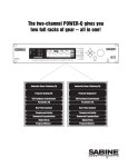
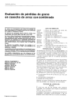
OPERATING
GUIDE
www.Sabine.com
INSIDE THIS GUIDE:
SDA-102 Controls
2
Digital Delay Advantage
3-6
Delay Applications
6-8
Calculating Delay Time
9
Basic Operating Instructions 9
Engineering Specifications
10
FCC Information
10
Safety Information
11
Warranty
12
SDA-102
Front Panel
SDA-102
Back Panel
CONGRATULATIONS! You have chosen the ultimate digital delay for acoustical
alignment of speaker systems in auditoriums, churches, stadiums, theaters, conference rooms, and venues of all sizes and designs. For an explanation of the digital
delay solution and advantage, see page 3. For the delay application guide, turn to
page 6.
Special features of the SDA-102 Instant Delay:
• One input, two outputs
• 20-bit A/D & D/A converters with 24-bit digital processing
• Up to 999.98 millisecond delay
• 20 microsecond resolution
• Input and output level controls
• Front panel lockout
• Optional rack tray holds up to six units
MADE IN USA. © 1997 Sabine Inc.
○
○
○
○
○
○
○
○
○
○
○
○
○
○
○
○
○
○
○
○
○
○
○
○
○
○
○
○
○
○
○
○
○
○
○
○
○
○
○
○
○
○
○
○
○
○
○
○
○
○
○
○
○
○
○
○
○
SDA-102 Front & Back Panels
POWER
The ON/OFF power switch is a two-position push button switch.
The LED display illuminates on power-up.
ACTIVE/BYPASS
In Active mode, the unit delays the input signal. When the
BYPASS button is depressed, the unit is in Bypass mode. If the
unit is turned off, it must be in Bypass to pass audio.
INPUT LEVEL CLIP INDICATOR
The red clip LED comes on when the input level is 6dB below
clipping level. Adjust the clip IN so that the SDA's red clip LED
blinks intermittently during maximum program levels. Higher
levels cause clipping and distortion, and lower levels introduce
noise.
SIGNAL INDICATOR
The SIGNAL LED lights when the signal level is above -30dB of
clip level.
LEVEL IN
Use a small flathead screwdriver to increase or decrease the
input level.
LEVEL OUT A/B
The output level for channels A and B can be adjusted
individually. Use a screwdriver to increase or decrease the
output level for either channel. The output level is adjustable
from 0 to 100%. Full output level is +26dBV into 600 Ohms,
balanced. Peak output capability is +29dBV peak, balanced.
A/B SELECT & CHANNEL INDICATORS
This push button allows you to set delay time for channels A and
B separately. Select a channel using the A/B button, and the
corresponding channel indicator LED will light red. Then use
the arrow keys to adjust the delay time for that channel.
UP/DOWN ARROWS
Use the arrow keys to increase or decrease delay time (in
milliseconds) for either channel individually.
LED DISPLAY
The four-digit LED display shows delay time in milliseconds.
2
FRONT PANEL LOCKOUT SWITCH
The unmarked switch at the upper left of the back panel is the
front panel lockout switch. When in the UP position, the unit is
unlocked (default) and anyone can adjust the SDA's controls.
When the switch is in the DOWN position, the unit is locked,
and the delay time can't be changed.
12VDC ADAPTOR
The SDA external power supply is included with the unit. Use
of any other power supplies may cause fire, injury or permanent damage to the unit and WILL VOID THE WARRANTY.
INPUT/OUTPUT CONNECTORS
The SDA includes three Euroblock three-pin connectors. The
numbers 3-2-1 marked above the connectors refer to LOW (3) HIGH (2) - SHIELD (1).
○
○
○
○
○
○
○
○
○
○
○
○
○
○
○
○
○
○
○
○
○
○
○
○
○
○
○
○
○
○
○
○
○
○
○
○
○
○
○
○
○
○
○
○
○
○
○
○
○
○
○
○
○
○
○
○
○
THE DIGITAL DELAY ADVANTAGE: Synchronize loudspeakers,
eliminate comb filter distortion, align the acoustic image
Why Digital Delays?
The most intelligible sound occurs when two people speak face to face. The sound is loud
and dry and the direction of the sound aligns with the speaker. It stands to reason that the
most intelligible sound systems are the ones that come closest to emulating face to face
communication. If this is your goal, a digital delay is essential to your sound system.
Special thanks to
Hans Drobilitsch of
Hans Drobilitsch
Audio GmbH.
(Wollersdorf,
Austria) for his
invaluable technical
advice.
Until recently, a digital delay’s cost was prohibitive for the average user. Only high-end
applications could justify the cost. But recent drops in component prices now put the benefits
of digital delays within affordable reach of every user.
There are three distinct applications for digital delays. The first and most important is
synchronization of the loudspeakers to control excess reverberation and echo. Secondly,
digital delays help control comb filter distortion, and finally, digital delays are useful for
aligning the acoustic image so the direction of the sound seems to be coming from the
performer rather than the loudspeaker.
This manual goes beyond the typical operating guide that only explains the front and back
panel adjustments. Instead, we discuss the basic acoustical concepts needed to get the
most out of your SDA-102 and present examples of several practical applications.
Loudspeaker Synchronization
Sound travels at about 1,130 feet per second in air, or about 1 millisecond per foot. On the
other hand, electronic signals travel almost one million times faster through your sound
system to the loudspeakers. The main task of digital delays is to synchronize multiple
loudspeakers so the sound traveling different distances arrives at the listener’s ears at about
the same time. Synchronizing the loudspeakers reduces reverberation and echoes for
improved intelligibility.
How to Synchronize Your Signals
There are several powerful tools available for precisely measuring the time a loudspeaker
signal takes to arrive at a certain point in the audience. Most of these tools are very sophisticated and tend to be quite expensive. Fortunately, simpler tools are sufficient for most
applications.
In the 1930’s, engineers synchronized the low and high frequency speakers in movie theaters
by feeding a sharp click through the system. They moved the speakers until they could only
hear a single sharp click coming from both speakers. You can use this same method with a
common child’s toy called a clicker. Pressing the thin metal strip makes a loud sharp click.
A clicker is especially useful when synchronizing the direct sound from the performer with the
sound from the loudspeakers.
Alternatively, you can use a phase checker especially for synchronizing the signals of two
loudspeakers (either LF and HF or two full range systems) since most of the phase checkers
include a click generator and receiver. Phase checkers are quite affordable and have other
uses besides synchronizing.
Processing (or Group) Delays
Converting signals back and forth from the analog to digital domain always delays the signal
a little. These conversion delays are often called processing (or group) delays, and usually
range between 0.9 to 5 milliseconds. You will notice that Sabine delays always display the
processing delay as the smallest possible delay value. For the SDA-102, the processing
delay is 0.9 milliseconds. You can simply bypass the unit for 0 seconds delay.
3
○
○
○
○
○
○
○
○
○
○
○
○
○
○
○
○
○
○
○
○
○
○
○
○
○
○
○
○
○
○
○
○
○
○
○
○
○
○
○
○
○
○
○
○
○
○
○
○
○
○
○
○
○
○
○
○
Not all manufacturers acknowledge processing delays in their specifications, but you must
take them into account when synchronizing your system. Make sure all digital equipment is
on and not bypassed when synchronizing. Also, be careful to make an appropriate adjustment in your delay lines if you later add any type of digital equipment to the system.
Center Cluster Speakers
Center cluster speakers offer several advantages over systems that have speakers mounted
on the sides. The most obvious advantage is that the distance to the closest and most
distant locations in the audience is almost equal, so most listeners hear about the same
level. Center clusters also offer two other advantages regarding the visual imaging.
Studies have shown that people can detect even small horizontal changes in the direction of
a sound source, but vertical shifts are much less noticeable. This suggests that the sound
from center-cluster speakers is more likely to be visually aligned with the performer than
loudspeakers placed on each side of the stage.
All those in the audience who are closer to the performer than the center cluster will hear the
direct sound from the performer before they hear the sound from the loudspeakers. This
makes the sound seem to come from the performer, not the loudspeakers. (See the Precedence Effect below.)
Comb Filter Distortion
Many who took high school science may remember ripple tank experiments where waves are
generated from two separate point sources. The waves from each source combine to form
visible interference patterns. In some places, the wave crests and troughs are in phase so
they combined to make a larger wave. In other places the crests are out of phase, so the
crest of one wave source is canceled by the trough of the other. Ripple tank experiments
show the interference patterns are strongest when the amplitude of the waves from each
source is equal.
A similar interference occurs in sound systems when a signal is delayed and mixed back into
the original signal. These interference patterns are called COMB FILTERS because their
frequency response plots look like the teeth of a comb (see Figs. 1 & 2). There are a number
of common situations that cause comb filters. For example, when the program is played
through two loudspeakers, the loudspeaker that is farther away interferes with the closer
loudspeaker. Comb filters are also created when a performer is picked up by two microphones, one closer than the other. You even introduce comb filters by mixing digital effects
back into the “dry” signal at the mixer’s effects loop.
Fig. 1:
COMB FILTERS. Input
signal mixed with a 2 msec.
delayed signal. (Both signals
have the same amplitude.
Max. filter gain is +6dB, and
max. depth is -4.)
4
○
○
○
○
○
○
○
○
○
○
○
○
○
○
○
○
○
○
○
○
○
○
○
○
○
○
○
○
○
○
○
○
○
○
○
○
○
○
○
○
○
○
○
○
○
○
○
○
○
○
○
○
○
○
○
○
○
○
Fig. 2:
COMB FILTERS. Input
signal mixed with a 2 msec.
delayed signal. (Delayed
signal has 10dB less
amplitude. Max. filter gain is
+2.5dB, and max. depth is
-3.) Reducing the amplitude
of the delayed signal reduces
the comb filters' effect.
Calculating Comb Filter Frequencies
The frequencies of the reinforcements and cancellations depend on the delay time (the time
difference between the arrival time of the original signal and the delayed signal). The
frequency of the first cancellation occurs at 1/(2 x t)Hz, where t = the delay time in seconds.
The cancellations are separated by (1/ t)Hz. Fig. 3 shows how the comb filters change with
the delay time.
Fig. 3:
Comb filters get
closer as delay
time increases.
Comb Filter Amplitude
If the original signal and the delayed signal are the same amplitude, the reinforced frequencies increase in amplitude by 6dB, while the out-of-phase frequencies cancel completely to
-4 dB.
Comb filters cause a lot of problems. The frequencies that are reinforced are prone to excite
feedback, while the out-of-phase cancellations make the program sound thin and over
equalized.
Try this simple experiment to hear what comb filters do to your sound.
Fig. 4:
Comb filters
noticeably affect
your sound.
5
○
○
○
○
○
○
○
○
○
○
○
○
○
○
○
○
○
○
○
○
○
○
○
○
○
○
○
○
○
○
○
○
○
○
○
○
○
○
○
○
○
○
○
○
○
○
○
○
○
○
○
○
○
○
○
○
○
Stack two identical full-range loudspeakers as shown in Fig. 4. Carefully align the HF horns
and wire the speakers in mono. Stand in front while listening to your favorite full-spectrum
CD. Ask a friend to move the top speaker slowly away from you. The degradation in sound
quality you hear is caused by comb filters. The experiment is most dramatic when you use
good quality speakers.
Correcting Comb Filters
Comb filters are inevitable to some degree in every live sound system, and they cannot be
corrected with equalization. Fortunately, most comb filter problems can be reduced to a
minimum by synchronizing the signals and reducing the amplitude of the delayed signal. The
examples below show several practical applications.
The Precedence Effect: Aligning the Acoustic Image
Helmut Haas published a study in 1951 describing a series of experiments that demonstrates
how people perceive delayed signals and echoes. In his experiments, a listener was positioned between two speakers placed 3 meters away; one was placed 45 degrees to the right
and the other was placed 45 degrees to the left. When the same program was played
through both speakers simultaneously, the listener perceived the acoustic image (the
direction from which the sound seemed to be coming) centered between the speakers.
When Haas delayed the signal going to one of the speakers by somewhere between 5 to 35
milliseconds, the listener perceived a shift in the acoustic image to the speaker heard first.
While the delayed speaker did not contribute to the apparent direction of the sound, it did
make the program seem louder and “fuller.”
Haas showed that you must increase the loudness of the delayed signal by about 8 to 10 dB
(twice the perceived loudness) in order for the acoustic image to move back to the original
center position. Increasing the loudness more than this, or increasing the delay somewhat
more than 35 milliseconds, makes the delayed signal sound like an echo.
The phenomenon describing how the acoustic image follows the signal we hear first is called
the Precedence Effect. The phenomenon that makes two distinct sounds heard less than 35
msec. apart seem like only one sound is call the Haas Effect. However, the terms are often
used interchangeably in the sound industry.
THREE APPLICATIONS
APPLICATION I: Under-The-Balcony Speakers
Fig. 5:
Overhead view
of under-balcony
application.
6
Fig. 5 above shows a typical situation where the performer is amplified by a center cluster
hanging above the stage. Almost everybody in the audience will enjoy good sound, except
those seated in the shadow of the balcony. So we add an under-balcony speaker to fill in the
shadow.
○
○
○
○
○
○
○
○
○
○
○
○
○
○
○
○
○
○
○
○
○
○
○
○
○
○
○
○
○
○
○
○
○
○
○
○
○
○
○
○
○
○
○
○
○
○
○
○
○
○
○
○
○
○
○
○
○
Now we have sufficient volume under the balcony, but the sound from the two speakers
arrives at the listener’s ears some 76 to 84 milliseconds apart. The two signals, along with
their echoes, result in an unintelligible cacophony. We must delay the sound from the underbalcony speaker to synchronize the signals. Do we set the SDA-102 delay to 76 or 84
milliseconds? Obviously, the geometry will not allow us to exactly synchronize every location
under the balcony; we have to compromise.
First, you must consider the program type. For spoken word programs, you will produce the
best intelligibility if the signals from the under-balcony speakers arrive within 10 msec. of the
signals from the center cluster. Therefore we should set the delay to 84-86 msec. You can
allow a little more reverberation for programs that are mostly music.
Next, we must eliminate comb filter distortion. Find the axis where the levels of the center
cluster and under-balcony speaker are equal. (See "Comb Filter Distortion," p.4.) Use the
SDA-102 to precisely synchronize the speakers along this axis to eliminate the most severe
comb filters. Comb filters off the equal-level axis are much less of a problem since a louder
signal is not affected very much by a weaker signal.
Finally, you can experiment with adding 5 to 10 milliseconds delay to both sets of speakers to
enhance the Precedence Effect for the audience seated near the performer.
In the final analysis, every setting is a compromise, and your ear has to be the final judge.
Check the sound in several different locations throughout the auditorium and correct the most
severe irregularities.
Application II: Center Cluster with Front Fills
Fig. 6 below describes a typical application that has a stage with a microphone, a center
cluster above the stage, and front fills in front of the stage. There must be thousands of
installations throughout the world like this that "get by" without digital delays. But with the
SDA-102, you can improve the intelligibility and add a new quality without ringing up any
significant costs. Use the SDA-102 in this situation to align the visual image with the
acoustic image. The program is much more enjoyable when the amplified sound seems to
be originating with the performer, not the loudspeakers.
Fig. 6:
Synchronizing
center clusters
and front fills.
Find a central place in the audience where the center cluster is 6 to 8dB louder than the direct
sound from the performer. Delay them so that their sound arrives 5 to 8 milliseconds after
the direct sound from the performer. Experiment by bypassing the SDA-102 in and out to
hear how the source of the sound seems to move from the loudspeakers to the performer and
back. Now your ears have the same directional information as your eyes, so the performance will sound more natural and exciting. The best seats in the house just got better.
What about the front fills? Their purpose is to add intelligibility and listening comfort to the
first few rows nearest the stage by filling in the areas missed by the center clusters. Simply
7
○
○
○
○
○
○
○
○
○
○
○
○
○
○
○
○
○
○
○
○
○
○
○
○
○
○
○
○
○
○
○
○
○
○
○
○
○
○
○
○
○
○
○
○
○
○
○
○
○
○
○
○
○
○
○
○
○
add about 8 msec. to the front fills to take advantage of the Precedence Effect.
The 8 msec. setting presumes the performer is standing on the front few feet of the stage.
But some stages are well over 30 feet deep. What if there is a second performer standing 25
feet behind the first? The direct sound from his or her voice will reach the first few rows
about 25 msec. after the first performer's. The audience will perceive the first performer
directly and the second performer through the loudspeakers.
We can add the advantage of the Precedence Effect to the second performer by placing an
SDA-102 in the mixer's channel insert point and adding a 25 msec. delay.
Certainly taking advantage of the Precedence Effect is not as obvious to the audience as
eliminating feedback, but it is nice to know you did all that is possible to make the performance enjoyable.
Application III: Synchronizing the signals of a far-throw and short-throw loudspeaker.
In order to reach the proper coverage in larger venues, we often stack two full range speakers
- a short-throw center cluster for the audience below and a far-throw speaker for the back of
the auditorium. It is almost impossible to perfectly align the stacked speakers mechanically,
so comb filter distortion becomes a problem in the area where the levels from both speakers
are equal. The same thing happens with speakers mounted on the right and left sides.
Fig. 7:
Aligning far- and
short-throw
speakers. (The
level from both
speakers is equal.)
It is impossible to remove comb filters with equalization, but the SDA-102 eliminates them in
short order without affecting the spectral balance for the rest of the audience. Find the axis
where the levels from the two speakers are equal. This is where the comb filters are most
severe. Carefully adjust the SDA-102 so that the signal from both speakers arrives at
precisely the same time. The SDA provides 20 microsecond resolution for this purpose.
Use the same procedure to align speakers within a cluster when necessary.
8
○
○
○
○
○
○
○
○
○
○
○
○
○
○
○
○
○
○
○
○
○
○
○
○
○
○
○
○
○
○
○
○
○
○
○
○
○
○
○
○
○
○
○
○
○
○
○
○
○
○
○
○
○
○
○
○
○
CALCULATING DELAY TIME USING DISTANCE
Calculating delay time in terms of distance is a common and accepted method. For a good
start, estimate the delay at 1 millisecond per foot between speakers. Use the following
equation for more precise estimates:
Delay (milliseconds) = 1000
OR
Delay (milliseconds) = 1000
(
(
D (distance in feet)
1130
)
)
D (distance in meters)
344
These measurements presume standard temperature (68 degrees F, 20 degrees C) and
pressure (29.2 in. Hg., 760 mm Hg.). Sound travels slower in cooler or drier air and at higher
pressures. For example, the speed of sound decreases about 0.61 meters per second as the
temperature drops from 20 degrees C to 0 degrees C.
BASIC OPERATING INSTRUCTIONS
The SDA-102 Instant Delay is designed for acoustical alignment of speaker systems only, not
for use as an effect. Using the SDA for your speaker system fills will help the audience
perceive the sound as originating on the stage, making the sound more natural.
Follow these operating instructions for best results.
1. Place the SDA between the mixer and the power amplifier - but after all signal processing
equipment for the delayed speaker system. (If you're using a Sabine FBX Feedback
Exterminator, place the SDA after the FBX in the chain.)
2. Make sure that the SDA is patched in correctly and that it is powered up. (When
connecting the power supply to the SDA-102, angle the connector down, then
push the connector up into the input gently, with the lip facing up as shown. Do
not force the connector into or out of the SDA.) Play program material, and
adjust the input level using a small flathead screwdriver until the red clip LED
blinks intermittently during maximum program levels. (The red CLIP LED
comes on when the input level is 6dB below clipping level.) Higher levels
cause clipping and distortion, and lower levels introduce noise.
3. Adjust the output level for each channel individually, using a small screwdriver.
4. Press the A/B button to select channel A or B for setup. (The corresponding LED will
light to indicate which channel is being set.) Enter the desired delay time (in milliseconds) using the up/down arrow keys.
5. If you want to lock out the front panel controls so the delay time can't be reprogrammed,
set the lockout switch on the back panel to the DOWN position. (The factory default is in
the UP position, which is UNLOCKED.)
6. The SDA's memory backup allows the last configuration to be stored in memory, so the
delay time last programmed into the unit when it is powered down is the delay time that
appears when the unit is powered up again.
9
○
○
○
○
○
○
○
○
○
○
○
○
○
○
○
○
○
○
○
○
○
○
○
○
○
○
○
○
○
○
○
○
○
○
○
○
○
○
○
○
○
○
○
○
○
○
○
○
○
○
○
○
○
○
○
○
○
ENGINEERING SPECIFICATIONS
PERFORMANCE
Frequency Response: +/- 0.5 dB @ +22 dBV, 20 Hz to 20 kHz
Dynamic Range: >100 dB
THD: <0.01% @ 22 dBV @ 1 kHz
DIGITAL RESOLUTION
20 bit A/D & D/A
DELAY RANGE
0.90 - 999.98 milliseconds
INPUT/OUTPUT
Input Impedance: Balanced >10 K Ohms, PIN 2 high
Output Impedance: Balanced 10 Ohms nominal, PIN 2 high
Input/Output Maximum Signal Levels: Balanced +26 dBV peak
into 600 Ohms
Headroom: +22 dBV peak @ 4 dBV nominal input
I/O Connectors: Euroblock 3-pin
POWER INPUT
100, 117, 230 VAC +/-15%, 50/60 Hz, <12 Watt
Thermal fusing contained in wall mount transformer
MINIMUM INCREMENT
20 microseconds for all display readings
DIMENSIONS
1-U height, 1/6-RU width; 2.78 x 1.65 x 5.5 in. (6.95 x 4.13 x 13.75 cm)
Weight: <2.0 lb.
DISPLAY
4 digit numeric LED
Millisecond display
DISPLAY RESOLUTION
0.90 - 99.98 milliseconds, 20 microseconds
100.0 - 999.9 milliseconds, 100 microseconds
OPTION
SL6RACK Rack Tray (holds up to six units)
FRONT PANEL LOCKOUT SWITCH
SPECIFICATIONS SUBJECT TO CHANGE WITHOUT NOTICE.
FCC STATEMENT:
This device complies with Part 15, Class B, of the FCC Rules. Operation is subject to the following two conditions: (1) This device may not cause
harmful interference; and (2) This device must accept any interference received, including interference that may cause undesired operation.
10
○
○
○
○
○
○
○
○
○
○
○
○
○
○
○
○
○
○
○
○
○
○
○
○
○
○
○
○
○
○
○
○
○
○
○
○
○
○
○
○
○
○
○
○
○
○
○
○
○
○
○
○
○
○
○
○
○
SAFETY INFORMATION
Warning! This equipment must be earthed.
Caution! Risk of electric shock. Do not open.
Caution! Shock hazard. Do not remove covers. No user
serviceable parts inside. Refer servicing to qualified service
personnel.
Warning! To reduce the risk of fire or electric shock, do not
expose this product to rain or moisture.
Attention! Cet appareil doit être relié à la terre.
Attention! Risque de choc électrique; ne pas ouvrir.
Attention! Risque de choc; ne pas oter les capots. Aucune
pièce accessible à l'intérieur. S'addresser à un technicien
qualifié.
Attention! Pour réduire le risque d'incendie ou de choc
électrique, ne pas laisser l'appareil sous la plouie ou à
l'humidité.
Achtung! Dieses Gerät muss schutzgeerdet sein.
Achtung! Gefar eines elektrischen Stormschlags. Gehause
nicht öffnen.
Achtung! Gefar eines elektrischen Stormschlags. Gehäuse
nicht öffnen. Keine con Benutzer zu bedienenden Teile im
Geräteinneren.
Überlassen Sie das Gerät zu Servicezwecken nur geschultem
Fachpersonal.
Um Brandgefar oder das Risiko eines elektrischen Schlags
auszuschließen, das Gerät vor Nässe und Feuchtigkeit
schützen.
Warning!
The SDA-102 is designed to operate from standard AC power.
Please be sure the power in your area is compatible with the
power module accompanying the unit. Using the wrong input
voltage may cause permanent damage to the unit and will void
the warranty.
The SDA-102 is supplied with one of the following AC adapter
modules:
Japan
U.S./North America
Continental Europe
United Kingdom
Australia
100 VAC
120 VAC
230 VAC
240 VAC
240 VAC
Advertencia! Este equipo debe estar conectado a tierra.
Precaución! Reisgo de descarga eléctrica. No abrir.
Precaución! Riesgo de descarga eléctrica. No desmontar las
tapas. Piezas interiores no reparables por el usuario. Reparable sólo por personal cualificado.
Advertencia! Para reducir el riesgo de incendio o de descarga
eléctrica no exponga este producto a la lluvia o humedad.
CAUTION:
EXPOSURE TO EXTREMELY HIGH NOISE LEVELS MAY CAUSE A PERMANENT
HEARING LOSS. INDIVIDUALS VARY CONSIDERABLY IN SUSCEPTIBILITY TO
NOISE INDUCED HEARING LOSS, BUT NEARLY EVERYONE WILL LOSE SOME
HEARING IF EXPOSED TO SUFFICIENTLY INTENSE NOISE FOR A SUFFICIENT
TIME. THE U.S. GOVERNMENT'S OCCUPATIONAL SAFETY AND HEALTH
ADMINISTRATION (OSHA) HAS SPECIFIED THE FOLLOWING PERMISSIBLE
NOISE LEVEL EXPOSURES:
DURATION/DAY IN HOURS
8
6
4
3
2
1-1/2
1
1/2
1/4 or less
SOUND LEVEL IN dBA, SLOW RESPONSE
90
92
95
97
100
102
105
110
115
ACCORDING TO OSHA, ANY EXPOSURE IN EXCESS OF THE ABOVE
PERMISSIBLE LIMITS COULD RESULT IN HEARING LOSS. EAR PLUGS OR
PROTECTORS IN THE EAR CANALS OR OVER THE EARS MUST BE WORN
WHEN OPERATING THIS DEVICE IN ORDER TO PREVENT A PERMANENT
HEARING LOSS. IF EXPOSURE IS IN EXCESS OF THE LIMITS AS SET FORTH
ABOVE, TO ENSURE AGAINST POTENTIALLY DANGEROUS EXPOSURE TO
HIGH SOUND PRESSURE LEVELS, IT IS RECOMMENDED THAT ALL PERSONS
EXPOSED TO EQUIPMENT CAPABLE OF PRODUCING HIGH SOUND
PRESSURE LEVELS SUCH AS THIS DEVICE BE PROTECTED BY HEARING
PROTECTORS WHILE THIS UNIT IS IN OPERATION.
1. Read all safety and operating instructions before using this product.
2. All safety and operating instructions should be retained for future reference.
3. Obey all cautions in the operating instructions and on the unit.
4. All operating instructions should be followed.
5. This product should not be used near water, i.e a bathtub, sink, swimming pool,
wet basement, etc.
6. This product should be located so that its position does not interfere with its
proper ventilation. It should not be placed flat against a wall or placed in a built-in
enclosure that will impede the flow of cooling air.
7. This product should not be placed near a source of heat such as a stove or
radiator.
8. Connect only to a power supply of the type marked on the unit adjacent to the
power.
9. Never break off the ground pin on the power supply cord.
10. Power supply cords should always be handled carefully. Never walk or place
equipment on power supply cords. Periodically check cords for cuts or signs of
stress, especially at the plug and the point where the cord exits the unit.
11. The power supply cord should be unplugged when the unit is to be unused for
long periods of time.
12. Care should be taken so that objects do not fall and liquids are not spilled into
the unit through the ventilation holes or any other openings.
13. This unit should be checked by a qualified service technician if:
A. The power supply cord or plug has been damaged.
B. Anything has fallen or been spilled into the unit.
C. The unit does not operate correctly.
D. The unit has been dropped or the enclosure damaged.
14. The user should not attempt to service this equipment. All service work should
be done by a qualified service technician.
OSHA 2201; 1995 revised.
11
○
○
○
○
○
○
○
○
○
○
○
○
○
○
○
○
○
○
○
○
○
○
○
○
○
○
○
○
○
○
○
○
○
○
○
○
○
○
○
○
○
○
○
○
○
○
○
○
○
○
○
○
○
○
○
○
○
ONE-YEAR LIMITED WARRANTY:
THIS LIMITED WARRANTY VALID ONLY WHEN PURCHASED AND
REGISTERED IN THE UNITED STATES OR CANADA. ALL EXPORTED PRODUCTS ARE SUBJECT TO WARRANTY AND
SERVICES TO BE SPECIFIED AND PROVIDED BY THE AUTHORIZED DISTRIBUTOR FOR EACH COUNTRY.
Ces clauses de garantie ne sont vaiables qu’aux Etats-Unis et au
Canada. Dans tous les autres pays, les clauses de garantie et de
maintenance sont fixees par le distributeur national et assuree par lui
selon la legislation en vigueur.
Diese Garantie ist nur in den USA and Kanada gultig. Alle ExportProdukte sind der Garantie und dem Service des Importeurs des
jewelligen Landes untervorfen.
Esta garantia es valida solamente cuando el producto es comprado en
E.U. continentales o en Canada. Todos los productos que sean
comprados en el extranjero, estan sujetos a las garantias y servicio que
cada distribuidor autorizado determine y otrezca en los diterentes paises.
ONE-YEAR LIMITED WARRANTY/REMEDY
SABINE, INC. (“SABINE”) warrants this product to be free from defects in
material and workmanship for a period of one (1) year from date of
purchase PROVlDED, however, that this limited warranty is extended only
to the original retail purchaser and is subject to the conditions, exclusions
and limitations hereinafter set forth:
CONDITIONS, EXCLUSIONS AND LIMITATIONS OF LIMITED
WARRANTIES
These limited warranties shall be void and of no effect if:
a. The first purchase of the product is for the purpose of resale; or
b. The original retail purchase is not made from an AUTHORIZED
SABINE DEALER; or
c. The product has been damaged by accident or unreasonable use,
neglect, improper service or maintenance, or other causes not arising out
of defects in material or workmanship; or
d. The serial number affixed to the product is altered, defaced or
removed; or
e. The power supply grounding pin is removed or otherwise defeated. In
the event of a defect in material and/or workmanship covered by this
limited warranty, Sabine will repair the defect in material or workmanship
or replace the product, at Sabine’s option; and provided, however, that, in
any case, all costs of shipping, if necessary, are paid by you, the
purchaser.
THE WARRANTY REGISTRATION CARD SHOULD BE ACCURATELY COMPLETED, MAILED TO AND RECEIVED BY SABINE
WITHIN FOURTEEN (14) DAYS FROM THE DATE OF YOUR
PURCHASE.
In order to obtain service under these warranties, you must:
a. Bring the defective item to any AUTHORIZED SABINE DEALER and
present therewith the ORIGINAL PROOF OF PURCHASE supplied to you
by the AUTHORIZED SABINE DEALER in connection with your purchase
from him of this product. If the DEALER is unable to provide the
necessary warranty service, you will be directed to the nearest other
SABINE AUTHORIZED DEALER which can provide such service.
OR
b. Call Sabine for a RETURN AUTHORIZATION NUMBER and ship the
defective item, prepaid, to:
SABINE, INC.
13301 HIGHWAY 441
ALACHUA, FL 32615-8544 USA
including therewith a complete, detailed description of the problem,
together with a legible copy of the original PROOF OF PURCHASE and a
complete return address. Upon Sabine’s receipt of these items:
If the defect is remedial under the limited warranties and the other terms
and conditions expressed have been complied with, Sabine will provide
the necessary warranty service to repair or replace the product and will
return it, FREIGHT COLLECT, to you, the purchaser. Sabine’s liability to
the purchaser for damages from any cause whatsoever and regardless of
the form of action, including negligence, is limited to the actual damages
MADE IN USA.
Manufactured by: Sabine, Inc. • 13301 Highway 441 • Alachua, FL 32615-8544 USA •
Phone: (904) 418-2000 • Fax: (904) 418-2001 • www.sabine.com
up to the greater of $500.00 or an amount equal to the purchase price of
the product that caused the damage or that is the subject of or is directly
related to the cause of action. Such purchase price will be that in effect
for the specific product when the cause of action arose. This limitation of
liability will not apply to claims for personal injury or damage to real
property or tangible personal property allegedly caused by Sabine’s
negligence. Sabine does not assume liability for personal injury or
property damage arising out of or caused by a non-Sabine alteration or
attachment, nor does Sabine assume any responsibility for damage to
interconnected non-Sabine equipment that may result from the normal
functioning and maintenance of the Sabine equipment.
UNDER NO CIRCUMSTANCES WILL SABINE BE LIABLE FOR ANY
LOST PROFITS, LOST SAVINGS, ANY INCIDENTAL DAMAGES OR
ANY CONSEQUENTIAL DAMAGES ARISING OUT OF THE USE OR
INABILITY TO USE THE PRODUCT, EVEN IF SABINE HAS BEEN
ADVISED OF THE POSSIBILITY OF SUCH DAMAGES.
THESE LIMITED WARRANTIES ARE IN LIEU OF ANY AND ALL
WARRANTIES, EXPRESS OR IMPLIED, INCLUDING BUT NOT
LIMITED TO, THE IMPLIED WARRANTIES OF MERCHANTABILITY
AND FITNESS FOR A PARTICULAR USE; PROVIDED, HOWEVER,
THAT IF THE OTHER TERMS AND CONDITIONS NECESSARY TO
THE EXISTENCE OF THE EXPRESS LIMITED WARRANTIES, AS
HEREINABOVE STATED, HAVE BEEN COMPLIED WITH, IMPLIED
WARRANTIES ARE NOT DISCLAIMED DURING THE APPLICABLE
ONE-YEAR PERIOD FROM DATE OF PURCHASE OF THIS PRODUCT.
SOME STATES DO NOT ALLOW LIMITATION ON HOW LONG AN
IMPLIED WARRANTY LASTS, OR THE EXCLUSION OR LIMITATION
OF INCIDENTAL OR CONSEQUENTIAL DAMAGES, SO THE ABOVE
LIMITATIONS OR EXCLUSIONS MAY NOT APPLY TO YOU. THESE
LIMITED WARRANTIES GIVE YOU SPECIFIC LEGAL RIGHTS, AND
YOU MAY ALSO HAVE OTHER RIGHTS WHICH MAY VARY FROM
STATE TO STATE.
THESE LIMITED WARRANTIES ARE THE ONLY EXPRESS
WARRANTIES ON THIS PRODUCT, AND NO OTHER STATEMENT,
REPRESENTATION, WARRANTY OR AGREEMENT BY ANY PERSON
SHALL BE VALID OR BINDING UPON SABINE.
In the event of any modification or disclaimer of express or implied
warranties, or any limitation of remedies, contained herein conflicts with
applicable law, then such modification, disclaimer or limitation, as the case
may be, shall be deemed to be modified to the extent necessary to
comply with such law.
Your remedies for breach of these warranties are limited to those
remedies provided herein, and Sabine gives this limited warranty only with
respect to equipment purchased in the United States of America.
INSTRUCTIONS-WARRANTY REGISTRATION CARD
1. Mail the completed WARRANTY REGISTRATION CARD to:
SABINE, INC.
13301 HIGHWAY 441
ALACHUA, FL 32615-8544 USA
a. Keep the PROOF OF PURCHASE. In the event warranty service is
required during the warranty period, you will need this document. There
will be no identification card issued by Sabine, Inc.
2. IMPORTANCE OF WARRANTY REGISTRATION CARDS AND
NOTIFICATION OF CHANGES OF ADDRESS:
a. Completion and mailing of WARRANTY REGISTRATION CARDS Should notification become necessary for any condition that may require
correction, the REGISTRATION CARD will help ensure that you are
contacted and properly notified.
b. Notice of address changes - If you move from the address shown on
the WARRANTY REGISTRATION CARD, you should notify Sabine of the
change of address so as to facilitate your receipt of any bulletins or other
forms of notification which may become necessary in connection with any
condition that may require dissemination of information or correction.
3. You may contact Sabine directly by telephoning (904) 418-2000.
4. Please have the Sabine product name and serial number available
when communicating with Sabine Customer Service.
4/10/97
00.12.13 - hto