1
GE Energy
Industrial Solutions
EV Charging Station
Installation Manual Ed.02
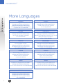
This manual
is available in
more languages.
See page 2
GE imagination at work
DuraStation™
EV Charging Station
More Languages
FRANÇAIS
Vous pouvez télécharger le manuel d’installation:
www.ge.com/fr/industrialsolutions
www.ge.com/be/industrialsolutions
Vous pouvez commander un exemplaire
sur papier par le code 451116
ESPAÑOL
Descarga el Manual de Instalación en:
www.ge.com/es/industrialsolutions
Puede solicitar la versión impresa
con el código 451114
ITALIANO
Il manuale di installazione può essere scaricato da:
www.ge.com/it/industrialsolutions
La versione stampata è ordinabile
con codice 451117
PORTUGUÊS
Manual de Instalação pode ser descarregado em:
www.ge.com/pt/industrialsolutions
Manual está igualmente disponível em versão
papel. Para pedir exemplares,
utilize o código 451120
DEUTSCH
Die Installations-Anleitung kann hier
heruntergeladen werden:
www.ge.com/de/industrialsolutions
Die gedruckte Version können Sie mit
der Nr. 451111 bestellen.
NEDERLANDS
Voor de installatiehandleiding surf naar:
www.ge.com/nl/industrialsolutions
www.ge.com/be/industrialsolutions
Een gedrukt exemplaar kan besteld
worden met code 451118
SUOMEN
SVENSKA
Asennusohjeet ovat ladattavissa:
www.ge.com/fi/industrialsolutions
Painettu versio on tilattavissa
tuotekoodilla 451115
Installationsmanual can laddas ner på:
www.ge.com/fi/industrialsolutions
Tryckt version kan beställas
med produktkoden 451112
DANSK
NORSK
Installation’s Manual kan downloaded’s:
www.ge.com/fi/industrialsolutions
Printet version kan bestilles med kode 451110
Installasjonsmanual kan nedlastes fra:
www.ge.com/fi/industrialsolutions
Papirversjon kan bestilles med kode 451119
ENGLISH
This Installation Manual can be downloaded:
www.ge.com/ex/industrialsolutions
www.ge.com/uk/industrialsolutions
Extra printed versions can be ordered
with code 451113
2
DuraStation™
EV Charging Station
Installation instructions
Installation Manual Ed.02
INDEX
1.
Safety and Compliance . . . . . . . . . . . . . . . . . . . . . . . . . . . . . . . . . . . . . . . . . . . . . . . . . . . . . 4
2.
Receiving . . . . . . . . . . . . . . . . . . . . . . . . . . . . . . . . . . . . . . . . . . . . . . . . . . . . . . . . . . . . . . 4
3.
Definition and Terms . . . . . . . . . . . . . . . . . . . . . . . . . . . . . . . . . . . . . . . . . . . . . . . . . . . . . . 4
4.
Technical Data . . . . . . . . . . . . . . . . . . . . . . . . . . . . . . . . . . . . . . . . . . . . . . . . . . . . . . . . . . 5
4.1.
Technical characteristics . . . . . . . . . . . . . . . . . . . . . . . . . . . . . . . . . . . . . . . . . . . . . . . . 5
4.2.
Catalogue data . . . . . . . . . . . . . . . . . . . . . . . . . . . . . . . . . . . . . . . . . . . . . . . . . . . . . . 6
4.2.1. TN-S distribution system . . . . . . . . . . . . . . . . . . . . . . . . . . . . . . . . . . . . . . . . . . . . 6
4.2.2. TN-S with surge arrestor . . . . . . . . . . . . . . . . . . . . . . . . . . . . . . . . . . . . . . . . . . . . 6
4.2.3. TN-C distribution system . . . . . . . . . . . . . . . . . . . . . . . . . . . . . . . . . . . . . . . . . . . . 6
5.
Hardware Installation . . . . . . . . . . . . . . . . . . . . . . . . . . . . . . . . . . . . . . . . . . . . . . . . . . . . . . 7
5.1.
Before installing . . . . . . . . . . . . . . . . . . . . . . . . . . . . . . . . . . . . . . . . . . . . . . . . . . . . . . 7
5.2.
Safety requirements . . . . . . . . . . . . . . . . . . . . . . . . . . . . . . . . . . . . . . . . . . . . . . . . . . . 7
5.3.
Wiring information . . . . . . . . . . . . . . . . . . . . . . . . . . . . . . . . . . . . . . . . . . . . . . . . . . . . 7
5.4.
Installation overview and specifications . . . . . . . . . . . . . . . . . . . . . . . . . . . . . . . . . . . . . . . 8
5.5.
Compact pedestal. . . . . . . . . . . . . . . . . . . . . . . . . . . . . . . . . . . . . . . . . . . . . . . . . . . . . 9
5.6.
Back-to-back pedestal . . . . . . . . . . . . . . . . . . . . . . . . . . . . . . . . . . . . . . . . . . . . . . . . . 13
5.7.
Wall mounted . . . . . . . . . . . . . . . . . . . . . . . . . . . . . . . . . . . . . . . . . . . . . . . . . . . . . . 17
5.8.
Pole mounted . . . . . . . . . . . . . . . . . . . . . . . . . . . . . . . . . . . . . . . . . . . . . . . . . . . . . . 20
6.
Controller Settings . . . . . . . . . . . . . . . . . . . . . . . . . . . . . . . . . . . . . . . . . . . . . . . . . . . . . . . 23
7.
Network Setup Instructions. . . . . . . . . . . . . . . . . . . . . . . . . . . . . . . . . . . . . . . . . . . . . . . . . . 25
7.1.
Firewall and security considerations . . . . . . . . . . . . . . . . . . . . . . . . . . . . . . . . . . . . . . . . . 25
7.2.
Controller configuration . . . . . . . . . . . . . . . . . . . . . . . . . . . . . . . . . . . . . . . . . . . . . . . . 25
7.2.1. Introduction . . . . . . . . . . . . . . . . . . . . . . . . . . . . . . . . . . . . . . . . . . . . . . . . . . . 25
7.2.2. Prepare service laptop or PC . . . . . . . . . . . . . . . . . . . . . . . . . . . . . . . . . . . . . . . . . 26
7.2.3. Configuration server interface. . . . . . . . . . . . . . . . . . . . . . . . . . . . . . . . . . . . . . . . 28
7.3.
Recommended network designs for RFID authentication. . . . . . . . . . . . . . . . . . . . . . . . . . . . 31
7.3.1. Option 1: Stand-alone network configuration . . . . . . . . . . . . . . . . . . . . . . . . . . . . . . . 31
7.3.2. Option 2: Charging station network isolated from customer
Network with Host system in a DMZ . . . . . . . . . . . . . . . . . . . . . . . . . . . . . . . . . . . . . 35
7.3.3. Install EV100 RFID host application software . . . . . . . . . . . . . . . . . . . . . . . . . . . . . . . 40
7.3.4. Setup validation . . . . . . . . . . . . . . . . . . . . . . . . . . . . . . . . . . . . . . . . . . . . . . . . . 41
7.4
Setup without RFID authentication . . . . . . . . . . . . . . . . . . . . . . . . . . . . . . . . . . . . . . . . . . 43
7.5.
Reset controller to factory default. . . . . . . . . . . . . . . . . . . . . . . . . . . . . . . . . . . . . . . . . . 44
7.6.
Trouble shooting guide. . . . . . . . . . . . . . . . . . . . . . . . . . . . . . . . . . . . . . . . . . . . . . . . . 44
3
DuraStation™
1. Safety and Compliance
This document provides instructions to install the IEC DuraStation products included in section 4.2. Before installing
the DuraStation charging station, review this manual carefully and consult with a licensed contractor, licensed
electrician, and trained installation expert to insure compliance with local building codes, climate conditions,
safety standards and wiring regulations.
EV Charging Station
The DuraStation must be connected to a grounded, permanent wiring system. Connections to the DuraStation shall
comply with all local codes and ordinances.
Only a licensed contractor, and a licensed electrician in accordance with all local and national codes and standards
should install the DuraStation.
Under no circumstances will compliance with the information in this manual relieve the user of his/her responsibility
to comply with all applicable codes, safety standards or wiring regulations.
2. Receiving
Upon receipt of shipment, examine the package for damage that may have been sustained in transit.
If the shipping container must be opened outdoors, take proper precautions to prevent the entrance of moisture.
While unpacking, examine the product for broken, bent, or loose parts or other damage. If damage from shipment
is evident, file a damage claim with the transportation company and notify the nearest sales office.
3. Definition and Terms
• EV: Electrical Vehicle
• EVSE: EV Supply Equipment
• EV Charging station = Charging station = EVSE
• PE: Protective Earth
• Kiosk: main body of EVSE
• Host System/Host PC: The PC that runs the GE DuraStation Manager Application to manage authorization and
collect data from the Charging Stations.
• Firewall: A network security device that provides controlled access between two or more network segments,
denying anything except approved communications between the various network segments.
• DMZ: Demilitarized Zone. An isolated network segment attached to a separate connection point on a firewall.
This segment is then granted specific access to or from any other “Zone” to control who/what can connect INTO
the DMZ or what the system or systems within the DMZ can connect OUT to.
• Switch: A network device that provides multiple connection points for attaching devices (CS, KIOSK, etc) to an
individual segment of a communications network. For the purpose of this document, they are Ethernet network
switches.
• NIC: Network Interface Card. A PC card with an RJ45 port that provides Ethernet connectivity.
• Service laptop or PC: A laptop or PC used to configure individual EVSE stations via direct Ethernet connection
(use a cross-over cable)
4
DuraStation™
4. Technical Data
The DuraStation has a list of basic features that are upgradeable, resulting in a robust and reliable solution for the
need of EV charging infrastructure.
Installation instructions
• The socket satisfies mode 3 charging standards, and is optionally equipped with an electromechanical interlock.
• LED light to display charger status:
Green = Station active
Blinking Green = Vehicle connected, but not charging
Amber = Charging
Red = Fault occurred
• Option for a Radio Frequency Identification (RFID) reader:
users will gain charging authorization by swiping RFID cards in front of the readers.
• Ethernet network offered for RFID authorization service.
• RFID software application registers usage of the EVSE enabling data collection and will also monitor status of
communication between RFID and DuraStation.
• Residual current protection and auto re-closure.
• Vehicle ground monitoring circuit.
• Single phase metering.
4.1. Technical characteristics
IEC Compliant
Mode 3 per IEC 61851
Vehicle Interface
Type 2 connector per IEC 62196
Voltage and Current Rating
230VAC at 16A or 400VAC at 32A
AC Max. Charging Power Output**
22kW (400VAC at 32A)
3.6kW (230VAC at 16A)
AC Power Input
230VAC requiring only L1, N, and PE
400VAC requiring only L1, L2, L3, N and PE
Recommended Panel Breaker
Compact pedestal, Pole, Wall:
1x4-pole 40A , or 2-pole 20A breaker on dedicated circuit
Back-to-back pedestal:
2x4-pole 40A, or 2-pole 20A breaker on dedicated circuit
Ground Fault Protection
Internal 30mA RCD with auto re-closure
Cold Load Start
Random start up between 0 and 15 minutes for peak protection
Local Area Network
CAT5 Ethernet
Network Communication Protocol
TCP/IP
RFID Reader
ISO15693 and ISO14443 compliant
Standby Power
5W typical
Outdoor Rated
Enclosure IP54-IK10, socket outlet IP44
Safety Compliance
IEC 61851 and IEC 62196 compliant
CE Marking Certification
CE
Low Voltage (2006/95/EG) and EMC Directive (2004/108EC).
Resistance against surges
IEC 61851 compliant
EMI Compliance
IEC 61851 compliant
Operating Temperature
-30°C to +50°C ambient
Operating Humidity
Up to 95% non-condensing
Approximate Shipping Weights
Compact pedestal: 30kg
Back-to-back pedestal: 45kg
Pole: 25kg
Wall: 25kg
Dimensions HxWxD (in mm)
Compact pedestal: 1300 x 275 x 200
Back-to-back pedestal: 1300 x 350 x 300
Pole: 800 x 237 x 200
Wall: 800 x 237 x 200
** The maximum available power consumption is determined by the DuraStation. The actual power consumption is
determined by the EV.
5
DuraStation™
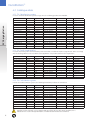
4.2. Catalogue data
4.2.1. TN-S distribution system
For use in electrical distribution systems of type TN-S, the following products are available:
EV Charging Station
Cat No.
EVSPE16A1P1N
EVSPE32A3P1N
EVSPE16A1P2N
EVSPE32A3P2N
EVSPE16A1P1R
EVSPE32A3P1R
EVSPE16A1P2R
EVSPE32A3P2R
EVSWA16A1P1N
EVSWA32A3P1N
EVSWA16A1P1R
EVSWA32A3P1R
EVSPO16A1P1N
EVSPO32A3P1N
EVSPO16A1P1R
EVSPO32A3P1R
Ref. No.
450100
450101
450102
450103
450104
450105
450106
450107
450108
450109
450110
450111
450112
450113
450114
450115
Type
Pedestal
Pedestal
Pedestal
Pedestal
Pedestal
Pedestal
Pedestal
Pedestal
Wall
Wall
Wall
Wall
Pole
Pole
Pole
Pole
Max Output
230V 16A 1 phase
400V 32A 3 phase
230V 16A 1 phase
400V 32A 3 phase
230V 16A 1 phase
400V 32A 3 phase
230V 16A 1 phase
400V 32A 3 phase
230V 16A 1 phase
400V 32A 3 phase
230V 16A 1 phase
400V 32A 3 phase
230V 16A 1 phase
400V 32A 3 phase
230V 16A 1 phase
400V 32A 3 phase
No. of Sockets
1
1
2
2
1
1
2
2
1
1
1
1
1
1
1
1
RFID
N
N
N
N
Y
Y
Y
Y
N
N
Y
Y
N
N
Y
Y
Integrated Meter
Single phase
Singe phase
Single phase
Single phase
Single phase
Single phase
Single phase
Single phase
Single phase
Single phase
Single phase
Single phase
Single phase
Single phase
Single phase
Single phase
4.2.2. TN-S with surge arrestor
In certain electrical systems the DuraStation power circuit has to include an impulse surge arrestor device to comply
with the local regulations or the conditions of the application. See products below for this requirement:
Cat No.
EVSPE16A1P1N-SA
EVSPE32A3P1N-SA
EVSPE16A1P2N-SA
EVSPE32A3P2N-SA
EVSPE16A1P1R-SA
EVSPE32A3P1R-SA
EVSPE16A1P2R-SA
EVSPE32A3P2R-SA
EVSWA16A1P1N-SA
EVSWA32A3P1N-SA
EVSWA16A1P1R-SA
EVSWA32A3P1R-SA
Ref. No.
450131
450133
450139
450141
450132
450134
450140
450142
450135
450137
450136
450138
Type
Pedestal
Pedestal
Pedestal
Pedestal
Pedestal
Pedestal
Pedestal
Pedestal
Wall
Wall
Wall
Wall
Max Output
230V 16A 1 phase
400V 32A 3 phase
230V 16A 1 phase
400V 32A 3 phase
230V 16A 1 phase
400V 32A 3 phase
230V 16A 1 phase
400V 32A 3 phase
230V 16A 1 phase
400V 32A 3 phase
230V 16A 1 phase
400V 32A 3 phase
No. of Sockets
1
1
2
2
1
1
2
2
1
1
1
1
RFID
N
N
N
N
Y
Y
Y
Y
N
N
Y
Y
Integrated Meter
Single phase
Singe phase
Single phase
Single phase
Single phase
Single phase
Single phase
Single phase
Single phase
Single phase
Single phase
Single phase
RFID
N
N
N
N
Y
Y
Y
Y
N
N
Y
Y
Integrated Meter
Single phase
Singe phase
Single phase
Single phase
Single phase
Single phase
Single phase
Single phase
Single phase
Single phase
Single phase
Single phase
4.2.3. TN-C distribution system
In TN-C electrical distribution systems, the following DuraStation products are considered:
Cat No.
EVSPE16A1P1N-NC
EVSPE32A3P1N-NC
EVSPE16A1P2N-NC
EVSPE32A3P2N-NC
EVSPE16A1P1R-NC
EVSPE32A3P1R-NC
EVSPE16A1P2R-NC
EVSPE32A3P2R-NC
EVSWA16A1P1N-NC
EVSWA32A3P1N-NC
EVSWA16A1P1R-NC
EVSWA32A3P1R-NC
Ref. No.
450143
450145
450151
450153
450144
450146
450152
450154
450147
450149
450148
450150
Type
Pedestal
Pedestal
Pedestal
Pedestal
Pedestal
Pedestal
Pedestal
Pedestal
Wall
Wall
Wall
Wall
Max Output
230V 16A 1 phase
400V 32A 3 phase
230V 16A 1 phase
400V 32A 3 phase
230V 16A 1 phase
400V 32A 3 phase
230V 16A 1 phase
400V 32A 3 phase
230V 16A 1 phase
400V 32A 3 phase
230V 16A 1 phase
400V 32A 3 phase
No. of Sockets
1
1
2
2
1
1
2
2
1
1
1
1
CAUTION: In TN-C Networks, ensure that all earth connections are the same point, and also, as it is
indicated in the section “Wiring Information”, neutral and earth functions are combined.
6
DuraStation™
5. Hardware Installation
5.1. Before installing
Before any installation work is performed, study the entire manual and drawings furnished by the supplier for a
particular installation.
5.2. Safety requirements
Installation instructions
- Eye protection with appropriate glasses (especially when using an electrical drill).
- During the installation be sure not to connect the power distribution network cables without additional protection.
- Ensure that no power is connected at all times when working.
- Use appropriate tools for each function.
- Turn off equipment used during the installation (better unplugged), for a change or cleaning process.
- Comply with the general security requirements common to all electrical appliances.
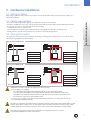
5.3. Wiring information
This equipment is designed for use in networks according to earthing types TN-C and TN-S, as it is shown in the
following wiring diagrams for each category:
Single-phase 230VAC at 16A
L1
L2
L3
L1
L2
L3
PE
N
CPN
PEN
Cat No. TN-C
Cat No. TN-S
L1
L1
N GND
TN-C distribution system
N GND
EVSPE16A1P1-X-NC
EVSPE16A1P1-X
EVSPE16A1P2–X-NC
EVSPE16A1P2-X
EVSWA16A1P1–X-NC
EVSWA16A1P1-X
EVSPO16A1P1–X-NC
TN-S distribution system EVSPO16A1P1-X
Three-phase 400VAC at 32A
CPN
L1
L2
L3
L1
L2
L3
PEN
PE
N
Cat No. TN-C
Cat No. TN-S
L1 L2 L3 N GND
L1 L2 L3 N GND
TN-C distribution system
EVSPE32A3P1-X-NC
EVSPE32A3P1-X
EVSPE32A3P2–X-NC
EVSPE32A3P2-X
EVSWA32A3P1–X-NC
EVSWA32A3P1-X
EVSPO32A3P1–X-NC
TN-S distribution system EVSPO32A3P1-X
IMPORTANT: In countries with different supply system as the previous,
• If a 110 voltage L-N is supplied,
- The single-phase DuraStation model (230VAC at 16A) can be connected to phase-phase;
- In the three-phase DuraStation model (400VAC at 32A), a possible solution would be to connect the
DuraStation to the output of an auto-transformer to go from 230 to 400 V. Connect the 3 phases and
the transformer to generate its own artificial neutral.
• In cases where the supply system does not correspond to any of the above, the wiring connection should
be evaluated by a qualified electrician.
CAUTION: The single-phase DuraStation model is designed to work only with a single-phase 230VAC (phase-neutral
or phase-phase) power supply system. The three-phase model is designed to be connected only to a three-phase
400VAC supply. Other connectivity to the power source may result in incorrect operation or a safety hazard.
NOTE: For serial connection of more than one DuraStation on a single power source, refer to the
corresponding installation instruction section below.
7
DuraStation™
5.4. Installation overview and specifications
This document describes how to install units of the DuraStation product line.
It includes step-by-step instructions for installing the body assembly for the following stations:
EV Charging Station
- Compact Pedestal
- Back-to-back Pedestal
- Wall Mounted
- Pole Mounted
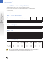
Table 1: Torque specifications
Type
Size
Characteristics
Rated Torque N/m
HBN Article
Pedestal
M12
DIN934, 304 Quality, Class 80
21
1202-23
M12x1000
DIN975 A2
21
1120-42
Wall mounted
M10x35
DIN933, 304 Quality, Class 80
14
1120-26
Pole mounted
M10x35
DIN933, 304 Quality, Class 80
14
1120-26
Table 2: Cable gland
Type
Cable Range (Inches)
Cable Range (mm)
Thread Length (mm)
Knockout Diameter (mm)
M32x1.5
0.669 - 0.984
18-25
12
32
Table3: Tools
Type
Characteristics
Screwdriver
0.6 x 3.5 (Used in ground connections)
Screwdriver
PZ2 (Used in wiring connections)
Hexagonal key
Socket size (mm): 19
Electric drill
Used in the wall mounted and pole mounted fixation.
Wire stripper, hammer, wall anchors.
Table 4: Contact blocks
Type Range
Size
1 Single wire
(solid)
(min-max)
mm2
1 Single wire
(semi-solid)
(min-max)
mm2
2 Single wires
(semi-solid)
(min-max)
mm2
1 Stranded
(flexible)
(min-max)
mm2
2 Stranded
(flexible)
(min-max)
mm2
Rated
conductor
cross-section
RK 35 (Phases)
M6
2.5-16
2.5-50
16-16
2.5-35
2.5-16
35
SL 35 (Earthing)
M6
2.5-16
2.5-50
16-16
2.5-35
2.5-16
35
WARNING: De-energize equipment before performing any work on the installation.
Make sure that the main breaker of the DuraStation is locked out, as well as the upstream breaker in
the distribution panel. (This is achieved with accessory KS 644929 in both cases)
8
DuraStation™
5.5. Compact pedestal
Description
Characteristics
Quantity
1
Kiosk unit
Compact pedestal
1
2
Base mounting assembly
-
1
3
Kiosk skirting
-
1
4
Hexagonal nuts M12
DIN934, 304 Quality, Class 80
8
5
Washer plain
DIN125A, 304 Quality
8
6
Lock washer
DIN127, 304 Quality
4
Installation instructions
Bill of material/Item
Procedure in 13 steps
1
1
3
(200) mm
X = + 10 cm recommended
4, 5, 6
X
2
X
(270) mm
X
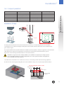
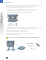
1. Identify a horizontal area for the pedestal location and create the corresponding cavity for the foundation.
The dimensions of the base mounting assembly and recommended minimum dimensions of the foundations are
given in above figure.
2. The power cable from the network includes the 2/4 cables for power (1/3 phases + N) and 1 for ground. The communication
cable (Ethernet) is required if the DuraStation is intended to be used with the RFID authentication system.
Refer to the section “Wiring Terminals Visuals” for connection locations.
IMPORTANT: verify that the mains voltage available in the installation corresponds to the voltage required
by the DuraStation and that the line has an appropriate cross section, ground conductor, complying with
current standards and wiring regulations
The cables must extend 80 cm to 1 m above the concrete, or according to local codes and wiring regulations.
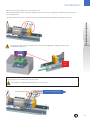
3. Place the base mounting assembly plate (2) into the foundation cavity, over the previously installed conduits.
To be located in the center (± 5cm)
Consider min
8-9 cm
a
Nuts M12
b
3
2
Recommended
12-16 cm
9
DuraStation™
4. Pour concrete to the level shown in the above figure. Verify that the final surface is completely smooth and horizontal.
(Consider a minimum of 8-9 cm to ensure the proper threading as shown in the figure above).
5. Screw the four nuts and washers (b) on the rods, as indicated in the figure above.
6. Insert the kiosk skirting (3) over the threaded rods, ensuring there is no contact with the previous nuts.
(Maintain the alignment of the kiosk skirting as shown in the figure on the previous page).
EV Charging Station
7. Place carefully the gasket (c), taking as reference the ground pin and fixation screws.
(C)
8. Open the door of the kiosk unit with the corresponding key by the door latch. Insert the kiosk unit over the threaded
rods above the kiosk skirting, ensuring that it is correctly aligned and no movement can take place.
9. Screw the internal nuts and washers (a) and apply a light torque.
10. Adjust bottom nuts and washers (b) ensuring the correct alignment.
11. Finally, tighten the internal nuts (a) again to secure the final position of the DuraStation.
(Refer to the torque specifications in table 1).
12. IMPORTANT: For proper earthing of the installed unit, remove the earth cable from pin (a) in the bottom
of the unit and connect it to pin (b). For this earth connection (b) use the fixation kit (M5) shown below.
10
DuraStation™
13. Connect the power supply wires to the power circuit:
Pull neutral and phases into the body assembly and connect them to the integrated terminal blocks as illustrated in
the following picture.
The earth cable of the system is connected to a contact block prepared specifically for earthing connections.
Installation instructions
To reduce the effects of external traction force, fix the power supply cables tightly by means of the
provided cable clamps (c).
Fixing
Point
C
Note: To connect the DuraStation in series with a second DuraStation (on a single power source), connect the
outgoing wires to the terminal blocks as shown below.
Refer to table 4 for details about admissible wire cross sections.
From upstream (grid)
To a second DuraStation
11
DuraStation™
EV Charging Station
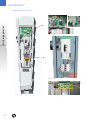
Wiring Terminals Visuals
Ethernet connector
Wires connection
Protective earth
12
DuraStation™
5.6. Back-to-back pedestal
Description
Characteristics
Quantity
1
Kiosk unit
Back-to-back
1
2
Base mounting assembly
-
1
3
Kiosk skirting
-
1
4
Hexagonal nuts M12
DIN934, 304 Quality, Class 80
8
5
Washer plain
DIN125A, 304 Quality
8
6
Lock washer
DIN127, 304 Quality
4
Procedure in 12 steps
1
1
4, 5, 6
2
(300) mm
X = + 10 cm recommended
3
X
Installation instructions
Bill of material/Item
X
(370) mm
X
1. Identify a horizontal area for the pedestal location and create the corresponding cavity for the foundation.
The dimensions of the base mounting assembly and recommended minimum dimensions of the foundations are
given in above figure.
2. The power cable from the network includes the 2/4 cables for power (1/3 phases + N) and 1 for ground.
The communication cable (Ethernet) is required if the DuraStation is intended to be used with the RFID
authentication system. Refer to the section “Wiring Terminals Visuals” for connection locations.
IMPORTANT: verify that the mains voltage available in the installation corresponds to the voltage
required by the DuraStation and that the line has an appropriate cross section, with ground
conductor, complying with current standards and wiring regulations.
The cables must extend 80 cm to 1 m above the concrete, or according to local codes and wiring regulations.
3. Place the base mounting assembly plate (2) into the foundation cavity, over the previously installed conduits.
To be located in the center (± 5cm)
Consider min 9-10 cm to
ensure proper threading
a
Nuts M12
b
3
2
Recommended minimum 12
and maximum of 16 cm
13
DuraStation™
4. Pour concrete to the level shown in the above figure. Verify that the final surface is completely smooth and
horizontal. (Consider a minimum of 9-10 cm to ensure the proper threading as shown in the figure above).
5. Screw the four nuts and washers (b) on the rods, as indicated in the figure above.
EV Charging Station
6. Insert the kiosk skirting (3) over the threaded rods, ensuring there is no contact with the previous nuts.
(Maintain the alignment of the kiosk skirting as shown in the figure on the previous page).
7. Open the door of the kiosk unit with the corresponding key by the door latch. Insert the kiosk unit over the threaded
rods above the kiosk skirting, ensuring that it is aligned correctly and no movement can take place.
8. Screw the internal nuts and washers (a) and applied a light torque.
9. Adjust bottom nuts and washers (b) ensuring the correct alignment.
10. Finally, tighten the internal nuts (a) again to secure the final position of the DuraStation.
(Refer to the torque specifications in table 1).
11. IMPORTANT: For proper earthing of the installed unit, remove the earth cable from pin (a) in the
bottom of the unit and connect it to pin (b).
For this earth connection (b) use the fixation kit (M5) shown below.
12. Connect the different power supply wires to the power circuit:
Pull neutral and phases into the body assembly and connect them to the integrated terminal blocks as illustrated in
the following picture.
The earth cable of the system is common for both of the circuits and it is connected to a contact block prepared
specifically for earthing connection. (Refer to the following “Wiring Terminals Visuals” section).
14
DuraStation™
To reduce the effects of external traction force, fix the power supply cables tightly by means of the
provided cable clamps (c).
C
Installation instructions
Fixing
Point
Note: To connect the DuraStation in series with a second DuraStation (on a single power source), connect the
outgoing wires to the terminal blocks, as shown below.
Connecting a second DuraStation can only be done if both of them are rated for 16A usage.
Refer to table 4 for details about admissible wire cross sections.
From upstream (grid)
To a second DuraStation
15
DuraStation™
EV Charging Station
Wiring Terminals Visuals
Ethernet connector
Power Supply
wires
Earthing
Connector
Wires connection
16
DuraStation™
5.7. Wall mounted
Description
Characteristics
Quantity
1
Kiosk unit
Wall mounted
1
2
Wall base bracket
-
1
3
WM fixation gasket
-
4
4
Flat washer M10
DIN9021, ISO 7093
4
5
Hexagonal screw M10x35
DIN933, 304 Quality, Class 80
4
6
Cable gland
M32
2
7
Ring
M32
2
8
Plastic lock nut
M32
2
9
Screw plug
DIN 46 320
1
Procedure in 5 steps
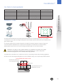
1. Drill 6 holes in the wall, as illustrated. Use the supplied template to ensure correct alignment.
IMPORTANT: Exercise extreme
caution when drilling holes in the
wall. There could be electrical
cables built-in the wall.
Installation instructions
Bill of material/Item
625
IMPORTANT: The maximum height
above the surface should be set to
meet any local or national requirements for persons with disabilities.
It is recommended that the lowest
part of the socket-outlet, shall be
located at a height between 0.4 m
and 1.5 m above ground level.
2. Fasten the wall base bracket to the wall, using adequate screws and anchors depending on the characteristics of the wall.
3. Install the kiosk wallmounted unit on the wall base bracket, using the fixation gaskets and washers as indicated in
the following picture. (Refer to the torque specifications in table 1).
5
4
3
2
1
9
6
7
8
17
DuraStation™
4. The power cable from the network includes the 2/4 cables for power (1/3 phases + N) and 1 for ground. The communication
cable (Ethernet) is required if the DuraStation is intended to be used with the RFID authentication system.
IMPORTANT: Verify that the mains voltage available in the installation corresponds to the voltage
required by the DuraStation and that the line has an appropriate cross section, with ground
conductor, complying with current standards and wiring regulations.
EV Charging Station
The cables must extend 40 to 60 cm above the wall surface, or according to local codes and wiring regulations.
To reduce the effects of external traction force, fix the power supply cables tightly by means of
the provided cable glands. Ensure to center the cables and turn the gland, until there is no cable
movement (Refer to table 2).
5. Connect the power supply wires to the power circuit:
Pull neutral and phases into the body assembly and connect them to the integrated terminal blocks as illustrated in
the following picture.
The earth cable of the system is connected to a contact block prepared specifically for that earthing connection.
Note: To connect the DuraStation in series with a second DuraStation (on a single power source), connect the
outgoing wires to the terminal blocks, as shown below.
Refer to table 4 for details about admissible wire cross sections.
From upstream (grid)
To a second DuraStation
18
DuraStation™
For this model, an extra outlet is provided in the back side of the DuraStation. It is used in case of a connection in
series with a second DuraStation, as it is shown.
Installation instructions
From upstream (grid)
To a second DuraStation
If the DuraStation is not connected to a second DuraStation, a Screw Plug (9) is used to close the additional outlet,
maintaining the appropriate IP protection rating of the system (IP54).
(9)
(9)
Outside view
Inside view
* Refer to “Charging Station Maintenance Procedures” manual for more details about replacement procedures in the
cable gland or screw plug.
19
DuraStation™
EV Charging Station
5.8. Pole mounted
Bill of material/Item
1
Description
Kiosk unit
Characteristics
Pole mounted
Quantity
1
2
Base mounting assembly
-
1
3
WM fixation gasket
-
4
4
Flat washer M10
DIN9021, ISO 7093
4
5
Hexagonal screw M10x35
DIN933, 304 Quality, Class 80
4
6
Pole mounted clamp
-
2
7
Cable gland
M32
2
8
Ring
M32
2
9
Plastic lock nut
M32
2
10
Screw plug
DIN 46 320
1
Procedure in 6 steps
1. Drill the different holes in the pole to accommodate the two couplings and the two screws (already welded into the
base) for the base-mounting fixation.
IMPORTANT: Exercise extreme caution when drilling holes in the pole. There could be electrical cables
built-in the pole.
2. Insert the coupler into the hole and hold the body assembly in place using a temporary strap.
IMPORTANT: The maximum height above the surface should be set to meet any local or national
requirements for persons with disabilities. It is recommended that the lowest part of the
socket-outlet, shall be located at a height between 0.4 m and 1.5 m above ground level.
625
3. Strap the body assembly to the pole using
12 mm (0.472”), 1,2mm (0.030”) stainless steel
strapping.
(Possible diameters for the pole structure:
150-180 mm)
IMPORTANT: A high tension-strapping
tool has to be used to install the straps.
4. Install the kiosk pole-mounted unit, using the fixation gaskets and washers as indicated in the following picture.
(Refer to the torque specifications in table 1).
3
4
5
1
10
2
7
20
8
9
DuraStation™
5. The power cable from the network includes the 2/4 cables for power (1/3 phases + N) and 1 for ground.
The communication cable (Ethernet) is required if the DuraStation is intended to be used with the RFID
authentication system.
IMPORTANT: verify that the mains voltage available in the installation corresponds to the voltage
required by the DuraStation and that the line has an appropriate section, with ground conductor,
complying with current standards and wiring regulations.
To reduce the effects of external traction force, fix the power supply cables tightly by means of the
provided cable glands. Ensure to center the cables and turn the gland, until there is no cable
movement (Refer to table 2).
6. Connect the power supply wires to the power circuit: Pull neutral and phases into the body assembly and
connect them to the integrated terminal blocks as illustrated in the following picture.
The earth cable is connected to a contact block prepared specifically for earthing connections
Installation instructions
The cables must extend 40 to 60 cm above the pole surface, or according to local codes.
Note: To connect the DuraStation in series with a second DuraStation (on a single power source), connect the
outgoing wires to the terminal blocks, as shown below.
Refer to table 4 for details about admissible wire cross sections.
From upstream (grid)
To a second DuraStation
21
DuraStation™
EV Charging Station
For this model, an extra outlet is provided in the back side of the DuraStation. It is used in case of a connection in
series with a second DuraStation, as it is shown.
From upstream (grid)
To a second DuraStation
If the DuraStation is not connected to a second DuraStation, a Screw Plug (9) is used to close the additional outlet,
maintaining the appropriate IP protection rating of the system (IP54).
(9)
(9)
Outside view
Inside view
* Refer to “Charging Station Maintenance Procedures” manual for more details about replacement procedures in the
cable gland or screw plug.
22
DuraStation™
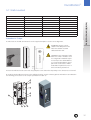
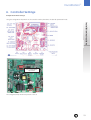
6. Controller Settings
Configuration Switch Settings
Using the configuration dip-switch S6, the controller can be placed into the desired operational mode.
Installation instructions
S6 - Configuration
Dip Switch
The configuration dip switch has positions 1 thru 8
23
DuraStation™
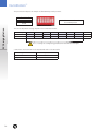
The picture below depicts an example of all CLOSED dip switch positions.
1 2 3 4 5 6 7 8
Pushed down on “number” side is
the CLOSED position
EV Charging Station
OPEN
The correct dip switch settings depend on the DuraStation model:
Current rating
1
2
3
4
5
6
7
8
EVS-PE16A1PX-X
OPEN
CLOSED
CLOSED
CLOSED
CLOSED
CLOSED
CLOSED
CLOSED*
EVS-PE32A3PX-X
OPEN
OPEN
CLOSED
OPEN
CLOSED
CLOSED
CLOSED
CLOSED*
These 7 settings are configured by production and shall not be changed.
* Switch 8 is used to determine the Operational Mode of the Controller
Current rating
8 position
Normal mode
CLOSED
Configuration mode
24
OPEN
DuraStation™
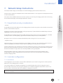
7.
Network Setup Instructions
This chapter details design recommendations for a GE EV Charging Station Network Infrastructure.
Network setup is required for installations that use RFID authentication. It is not required for DuraStation that do not
use RFID authentication.
7.1. Firewall and security considerations
- Firewall.
Any firewall used to provide isolation from the charging station network to any other network should, at a minimum,
provide “Statefull Packet Inspection”.
Anything less would not provide acceptable security and protection. SOHO firewalls are available that provide this
capability but there are some which do not.
Installation instructions
This section of the installation document covers the options for connecting the charging stations with a PC hosting
the EV100 GE EV Charging Station Manager application software.
Any firewall used for a DMZ environment should be a business class system (i.e. Cisco ASA, Checkpoint, SonicWall,
etc) and provide a true DMZ capability. Typical SOHO firewalls do NOT provide true DMZ capabilities.
GE supports the use of the Cisco ASA5505 firewall and provides settings for its use in this scenario.
- Physical Security.
Physical security is a necessary consideration in any installation of this type. There should be physical controls to
reduce the probability of a malicious entity’s chances of gaining access to any area of the system.
Network, maintenance access and power connections should be kept secured, i.e. all connections, behind an access
panel or door with a keyed lock to limit access. This door or access panel should be strong (metal as a suggestion)
and the lock should be of a type that is not commonly available to the general public.
All wiring should be enclosed in conduit meeting the local electrical and communications building codes.
And all conduits should be firmly attached to the secured “box” where the communications are terminated
within the charging station.
7.2. Controller configuration
7.2.1. Introduction
The Configuration Server Interface is used to make modifications to the network settings and to certain operation
parameters of the charging station controller.
The controller will boot into a default configuration. The network defaults will need to be changed in order to
accommodate the decisions in choosing the stand-alone or fire-walled configuration (described in sections 7.3.1.
and 7.3.2.) and to avoid conflicts with the installation of subsequent controllers.
Note: Each DuraStation needs to be configured individually using a service PC or laptop during the installation and
setup of the controllers.
25
DuraStation™
7.2.2. Prepare service laptop or PC
Action required ! In order to set up your service laptop or PC, make sure you have full Windows Administrator rights.
• Disable any firewalls and all other Ethernet and WiFi connections for the duration of the setup.
EV Charging Station
• Make sure no DuraStation is connected or at least not powered during these setup changes.
After the setup, you may want to set them back to your normal settings by undoing the same steps,
enable WiFi connections and firewalls.
Then follow these steps to configure your TCP/IP settings for communication with the DuraStation during setup.
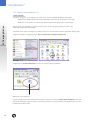
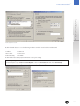
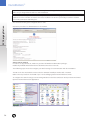
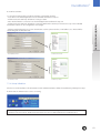
1. Open the network settings by going to Start > Control Panel > Network connections.
2. Right Click on Local Area Network and select to open the properties Window
Right click, select “Properties”
3. Scroll through the protocols used by the local area connection to find the Internet Protocol (TCP/IP). Select this
protocol by clicking on it and then click on the Properties button to open the window that will allow you to set the
IP address and Subnet mask.
26
DuraStation™
Installation instructions
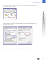
TCP/IP settings on the test PC
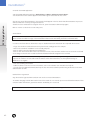
4. Click the Radio button to “Use the following IP Address” and then enter both the IP address and
Subnet mask as shown.
IP Address
Subnet Mask
Default Gateway
192.168.2.19
255.255.255.0
Leave Blank
5. Click OK and close both properties windows to save your settings
Note: Proxy Settings
In Internet Explorer, open “Tools”>”Internet Options”, click on “Connections” tab and then “LAN Settings”:
• Disable “Automatically detect settings” and “Use a proxy server for your LAN” as shown.
27
DuraStation™
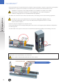
7.2.3. Configuration server interface
This paragraph describes how to access the DuraStation Controller Configuration Server Interface and which settings
can be modified.
EV Charging Station
Depending on the type of network chosen, each DuraStation needs to be configured according to the instructions given
in this document.
CAUTION: when manipulating the DuraStation, always make sure the power to the DuraStation is
switched off before coming close or touching any parts of the interior.
To configure each individual DuraStation
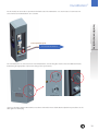
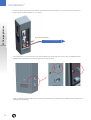
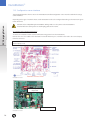
1. Switch off DuraStation main circuit breaker (Removing power from the DuraStation).
Connect the cross over cable to the DuraStation controller Ethernet port J1 and the other end to the service laptop
Ethernet connector.
Note: It is recommended to use a crossed Ethernet cable for direct connectivity between the DuraStation and the
service laptop or PC.
DuraStation Controller
S6 - Configuration
Dip Switch
Ethernet Connector J1
DuraStation Controller
28
DuraStation™
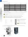
With the power removed, change the position of switch 8 on the S6 dip switch to OPEN for Configuration mode.
Keep the other switches in their original position.
3. Make sure the service laptop or PC has been configured as explained in the previous chapter.
4. Check that the LAN connection is established to the service laptop or PC (Status “Connected”)
Check if the Status is “Connected”
Installation instructions
2. Switch on the DuraStation main Circuit Breaker to power up the DuraStation in configuration mode.
a) As long as the Ethernet connection is not active, the DuraStation´s light is red.
b) As soon as the Ethernet connection is established. The DuraStation´s light continuously goes through a
sequence of colors (green – yellow – red), each for 5 seconds to indicate that the unit is in configuration mode.
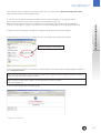
5. On the service PC or laptop, open a browser window and type in the address bar the following address and press
enter: http:// 192.168.2.2
Note: Should the DuraStation in question previously have been assigned a different default DuraStation IP address,
please enter that previously assigned IP address.
Note: If you have forgotten the IP address of this DuraStation, reset the controller.
(Refer to paragraph 7.5).
6. The controller will generate the following page:
Configuration Server Entry Screen
29
DuraStation™
EV Charging Station
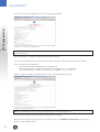
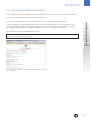
7. Pressing the “Enter Configuration” button, the following page will load:
Configuration Server Page with factory default values
Note: The default values normally do not need to be changed if the DuraStation does not use a RFID
authentication mode.
8. In the DuraStation configuration page modify settings as required.
The correct settings depend on the chosen network architecture and are described in a later chapter in detail.
There are 3 options for configuration:
• No RFID Authentication (default) (Refer to paragraph 7.4)
• RFID authentication in standalone network (Refer to paragraphs 7.3.1, 7.3.3 and 7.3.4)
• RFID authentication in firewalled network (Refer to paragraphs 7.3.2, 7.3.3 and 7.3.4)
9. After the desired settings are configured click on “Save”. The following page will load:
Configuration Server Confirmation Page
Note: The defaults values need to be changed depending on the network architecture.
Close the browser page and remove power to the DuraStation controller.
10. With Power removed, change the position of switch 8 on the S6, to CLOSED for Normal mode. Keep the other
switches in their original position.
30
DuraStation™
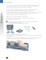
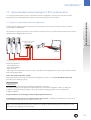
7.3. Recommended network designs for RFID authentication
It is strongly recommended using one of the below network configuration. The options provide the necessary
security levels for the Charging Station System network and other parts of the network.
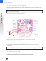
In this design the charging station network and its associated host system are not connected to the customer
network and it is independent.
This provides the greatest protection to the customer network, as there is no communication between the customer
network and the charging station network.
card
Charging Station Network
Ethernet switch
Installation instructions
7.3.1. Option 1: Stand-alone network configuration
card
Network Setup Option 1 – Stand-alone Configuration
Required components:
- Host Application PC
- Cat 5 Network Cables
- Ethernet Switch
- Card reader, accessory with ref. codes 411107 or 411108 from GE catalogue (Note: only the GE enrollment readers
work with this application)
STEP 1: DuraStation Controller Settings
Follow the instructions in the previous Controller Configuration section to set up each individual DuraStation
according to the following settings:
Action required ! - DuraStation IP
On initial power up the DuraStation IP address will default to 192.168.2.2
This must be changed to an appropriate address based on the network configuration. Failure to change the
IP address setting will impact the ability to bring up subsequent charging stations on the network due to
IP address collisions.
Assign IP addresses to the charging stations beginning with 192.168.2.22.
As additional charging stations are added increment the last octet, so that they are numbered in consecutive
order: 192.168.2.22, 192.168.2.23, 192.168.2.24, and so on.
Note: It is recommended to keep track of the different IP settings for each DuraStation by recording them on the
form found on the final page of this document.
31
DuraStation™
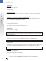
Action required ! - Subnet Mask
Set the Subnet Mask to 255.255.255.0
EV Charging Station
Action required ! - Default Gateway
Set the gateway to 0.0.0.0 (blank)
- Fan wired with contactor
Cars that require ventilation for charging must have the fan wired with main contactor and this option enabled.
- Disallow RCD Reclose
If this option is selected then charging is stopped for the vehicle at the first ground fault occurrence.
- If Authorization is Used: Unlock Cable from Charger Without Card Swipe
By default the charging station requires a card swipe to unlock the charging cable from the charger. When this
option is selected the cable is unlocked without a card swipe.
- Non-compliant SAEJ1772 behavior
Some earlier EV models equipped with a retrofit kit have a Pilot signal feedback that does not comply with the
SAE-J1772 / IEC61851 standard.
By default this option is not enabled.
- After a power loss enable a random delay before charging resumes
If there is a large number of DuraStation on a local feed, consider checking this box to enable a gradual increase in
load once the power is restored.
Action required ! - Require Authorization for charging
RFID authentication requires this check box to be checked on all DuraStation in the network.
Note: In the case of any modification to the “Require authentication for charging” option, or after a reset or replacement of the controller, the Station ID must be modified to a new ID not previously used on this network to avoid any
transaction data being lost.
- Host IP address
By default, the IP address is set to 192.168.2.19. Unless there is a collision with another setup, it is recommended to
keep this host address.
The network PC will need to be configured accordingly in the TCP/IP settings, as explained later in Step 2.
Note: The Host IP address on all DuraStation in the network, must match the TCP/IP settings of the network PC.
Action required ! - TCP Host Port & TCP Source Port
Change the value to 9500 for both the Host and Source Port to match the default value for the EV100 Application
software. Unless there is a collision by using this Port on the host PC, it is recommended to configure the EV100 application
to use port 9500 (by default) and all DuraStations in the network to also use port 9500 (factory default is 9000).
Note: The port number on all DuraStations in the network must match the port number defined during the EV100
Software installation.
- Enable DHCP
Keep this option disabled at all times.
- Allow charging if communication is not established
By default, this option is not selected. Checking this box will modify the behavior of the DuraStation in the case of
network loss:
• If unchecked, the DuraStation will not allow charging of a car in the case of network communication
failure between the DuraStation and the Host PC.
• If checked, the DuraStation will allow charging of a car despite network communication failure.
32
DuraStation™
Action required ! - Station ID information
Fill in the Station ID information to distinguish DuraStation from each other in the EV100 Application. It is important to
give each DuraStation a unique ID.
IDs will appear in the EV100 Application in the format “1-12-9” (e.g. Locality ID = 1, Facility ID = 12, Unit number = 9).
Note: In the case of any modification to the “Require authentication for charging” option, or after a reset or replacement of the controller, the Station ID must be modified to a new ID not previously used on this network to avoid any
transaction data being lost.
After the desired settings are configured click on “Save.
Repeat this procedure for all DuraStations in the network.
Installation instructions
Note: The Station ID information is how the EV100 application distinguishes between stations in the same network.
Make sure you assign different values to each DuraStation.
STEP 2: Host PC Settings
In order to set up your Host PC, make sure you have full Windows Administrator privileges.
Disable any firewalls and all other Ethernet and WiFi connections on this PC.
Then following steps are used to configure your TCP/IP settings for communication with all DuraStations connected
to your network.
The NIC on the host PC should be connected to the charging station network Ethernet switch.
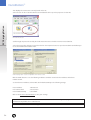
To configure the network settings on a PC running Windows XP or Windows 7, click the Start button and open the
Control Panel. Open the Network Connections application.
Network Connections
33
DuraStation™
EV Charging Station
This displays the connections currently found on the PC.
Select the icon for the Local Area Connection and double click to open the properties for this NIC.
LAN Network Connection
Scroll through the protocols used by the local area connection to find the Internet Protocol (TCP/IP).
Select this protocol by clicking on it and then click on the Properties button to open the window that will allow you
to set the IP address and Subnet mask.
Network Settings Option 1 (See the Configuration Server Interface section)
Click the Radio button to “Use the following IP Address” and then enter both the IP address and Subnet
mask as shown.
Set the Ethernet IP address, Subnet Mask, and Default Gateway to the following settings:
Host IP Address
Host Subnet Mask
Host Default Gateway
192.168.2.19
255.255.255.0
Leave Blank
Click on OK and close both windows to save your settings.
Note: The IP address above must match the Host IP address entered in the configuration page of all connected
DuraStations. By default, this is 192.168.2.19.
Note: Reboot PC to finalize with the configuration.
34
DuraStation™
Note: Proxy Settings
In Internet Explorer, open “Tools”>”Internet Options”, click on “Connections” tab and then “LAN Settings”:
• Disable “Automatically detect settings” and “Use a proxy server for your LAN” as shown.
Installation instructions
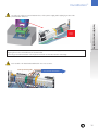
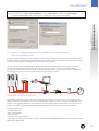
7.3.2. Option 2: Charging Station Network isolated from Customer Network
with Host System in a DMZ.
In this design, the charging stations are isolated from the customer network and the host system is within a DMZ
providing isolation from BOTH the Charging Station Network AND the Customer Network. This minimizes the risks of
someone compromising the charging station network or the host system.
The host system is within a DMZ providing isolation from both the charging station network and the customer
network and communicates with the charging stations via a rule or access control list entry which allows
communications between ONLY the host system and the charging stations. A rule or rules would be established
to permit specific systems on the customer network to access the host system.
card
Ethernet switch
card
ASA5505 Firewall
Customer Network
Optional proxy
Network Setup Option 2 –Networked Configuration with DMZ
This provides greater protection and isolation than the previous designs in this document. It’s not perfect as the
charging stations need to initiate some of the communications to the host system, so a rule or ACL will have to be
in place on the firewall to allow this communications. But it also isolates that communications from the customer
network. A properly configured firewall will provide greatly enhanced protection to the customer network.
Required components:
- Host application PC
- Cat 5 network cables
- Ethernet switch
- ASA5505 security plus firewall
- Card reader, accessory with ref. codes 411107 or 411108 from GE catalogue (Note: only the GE enrollment readers
work with this application)
35
DuraStation™
EV Charging Station
STEP 1: DuraStation Controller Settings
Follow the instructions in the Controller Configuration section to set up each individual DuraStation according to the
following settings:
Action required ! - DuraStation IP
On initial power up the DuraStation IP address will default to 192.168.2.2.This must be changed to an appropriate
address based on the network configuration. Failure to change the IP address setting will impact the ability to bring
up subsequent charging stations on the network due to IP address collisions.
Check with the local network administrator to determine which address ranges are currently in use at the site.
It is necessary to select ranges for the charging stations that are distinct from those currently in use to avoid
IP address conflicts.
If the 172.25.x.x. range is not in use the following settings should be implemented.
Set the DuraStation Ethernet IP address, Subnet Mask, and Default Gateway to the following settings:
DuraStation IP Address
172.25.0.xx
DuraStation Subnet Mask 255.255.255.0
DuraStation Default Gateway
172.25.0.1
Assign IP addresses to the charging stations beginning with 172.25.0.12. As additional charging stations are added
increment the last octet, so that they are numbered in consecutive order starting from 12. (Examples: 172.25.0.12,
172.25.0.13, 172.25.0.14, and so on).
All of the charging stations will use the same subnet mask 255.255.255.0 with the default gateway set to 172.25.0.1
Alternatively, if that range is in use, on the assumption that the 172.26.0.x. range is available use these
alternate settings:
DuraStation IP Address
172.26.0.xx
DuraStation Subnet Mask 255.255.255.0
DuraStation Default Gateway
172.26.0.1
This alternate setting will require the assignment of IP addresses to the charging stations beginning with 172.26.0.12
As additional charging stations are added increment the last octet, so that they are numbered as for example:
172.26.0.12, 172.26.0.13, 172.26.0.14, and so on. All of the charging stations will use the same subnet mask
255.255.255.0 with the default gateway set to 172.26.0.1.
Note: It is recommended to keep track of the different IP settings for each DuraStation by recording them on the
form found on the final page of this document.
- Subnet Mask
See above
- Default Gateway
See above
- Fan wired with contactor
Cars that require ventilation for charging must have the fan wired with main contactor and this option enabled.
- Disallow RCD Reclose
If this option is selected then charging is stopped for the vehicle at the first ground fault occurrence.
- If Authorization is Used: Unlock Cable from Charger Without Card Swipe
By default the charging station requires a card swipe to unlock the charging cable from the charger.
When this option is selected the cable is unlocked without a card swipe.
36
DuraStation™
- Non-compliant SAEJ1772 behavior
Some earlier EV models equipped with a retrofit kit have a Pilot signal feedback that does not comply with
the SAE-J1772 / IEC61851 standard.
By default this option is not enabled.
Action required ! - Require Authorization for charging
RFID authentication requires this check box to be checked on all DuraStations in the network.
Note: In the case of any modification to the “Require authentication for charging” option, or after a reset or
replacement of the controller, the Station ID must be modified to a new ID not previously used on this network
to avoid any transaction data being lost.
Action required ! - Host IP address
By default, the IP address is set to 192.168.2.19 and needs to be changed to one of the following options depending
on which address range is used.
- 172.25.1.100 in case of the DuraStation IP range being 172.25.0.xx
- 172.26.1.100 in case of the DuraStation IP range being 172.26.0.xx
Installation instructions
- After a power loss enable a random delay before charging resumes
If there is a large number of DuraStations on a local feed, consider setting this box to enable a gradual increase in
load once the power is restored.
The network PC will need to be configured accordingly in the TCP/IP settings, as explained below in Step 2.
Note: Make sure the Host PC is configured according to the same IP address settings as entered in the DuraStation
configuration server page.
Action required ! - TCP Host Port and TCP Source Port
Change the value to 9500 for both the Host and Source Port to match the default value for the EV100 Application
software. Unless there is a collision by using this Port on the host PC, it is recommended to configure the EV100
application to use port 9500 (by default) and all DuraStations in the network to also use port 9500 (factory default is 9000).
Note: The port number on all DuraStations in the network must match the port number defined during the EV100
Software installation.
- Enable DHCP
Keep this option disabled at all times.
- Allow charging if communication is not established
By default, this option is not selected. Checking this box will modify the behavior of the DuraStation in the case of
network loss:
• If unchecked, the DuraStation will not allow charging of a car in the case of network communication failure
between the DuraStation and the Host PC.
• If checked, the DuraStation will allow charging of a car despite of network communication failure.
Action required ! - Station ID information
Fill in the Station ID information to distinguish DuraStation from each other in the EV100 Application. It is important to
give each DuraStation a unique ID.
IDs will appear in the EV100 Application in the format “1-12-9” (e.g. Locality ID = 1, Facility ID = 12, Unit number = 9).
37
DuraStation™
Note: The Station ID information is how the EV100 application distinguishes between stations in the same network.
Make sure you assign different values to each DuraStation.
Note: In the case of any modification to the “Require authentication for charging” option, or after a reset or
replacement of the controller, the Station ID must be modified to a new ID not previously used on this network
to avoid any transaction data being lost.
EV Charging Station
After the desired settings are configured click on “Save.
Repeat this procedure for all DuraStations in the network.
STEP 2: Host PC Settings:
In order to set up your Host PC, make sure you have full Windows Administrator privileges.
Disable any firewalls and all other Ethernet and WiFi connections on this PC.
Then following steps are used to configure your TCP/IP settings for communication with the DuraStation.
The NIC on the host PC should be connected to the ASA5505 firewall port number 0/6. A network
Cable connects port 0/0 on the firewall to port 1 on the Charging Station Network Ethernet Switch.
To configure the network settings on a PC running Windows XP click the Start button and open the Control Panel.
Open the Network Connections application.
Network Connections
38
DuraStation™
This displays the connections currently found on the PC. Select the icon for the Local Area Connection and double
click to open the properties for this NIC.
Scroll through the protocols used by the local area connection to find the Internet Protocol (TCP/IP). Select this
protocol by clicking on it and then click on the Properties button to open the window that will allow you to set
the IP address and Subnet mask.
Installation instructions
LAN Network Connection
Network Settings Option 2 (See the Configuration Server Interface section)
Click the Radio button to “Use the following IP Address” and then enter both the IP address and Subnet
mask as shown.
39
DuraStation™
Action required ! Depending on the choice of IP address range above for the configuration of the DuraStations in the network, set the
Ethernet IP address, Subnet Mask, and Default Gateway to the corresponding settings:
IP Address
Subnet Mask
Default Gateway
172.25.1.100
255.255.255.0
172.25.1.1
or
IP Address
172.26.1.100
Subnet Mask
255.255.255.0
Default Gateway 172.26.1.1
EV Charging Station
Click on OK and close both windows to save your settings.
Note: Make sure the Host PC is configured according to the same IP address settings as entered in the DuraStation
configuration server page.
Note: Reboot PC to finalize with the configuration.
Note: Proxy Settings
In Internet Explorer, open “Tools”>”Internet Options”, click on “Connections” tab and then “LAN Settings”:
• Disable “Automatically detect settings” and “Use a proxy server for your LAN” as shown.
7.3.3. Install EV100 RFID Host Application Software
After the controller configuration of all DuraStations and the host PC’s TCP/IP setups have been completed, the Host
Application EV100 for RFID authentication needs to be installed.
In order to install EV100 application, make sure you have full Windows Administrator privileges.
The detailed installation steps are defined in the manual provided with the application on CD 1.
“EV100 – GE EV Charging Station Manager Application”.
For trouble shooting, please also refer to to the above noted manual.
Note: In order to install EV100 application, make sure you have full Windows Administrator privileges.
Before installing the application software, all DuraStations in the network must to be configured, as defined in previous
paragraphs 7.3.1 and 7.3.2.
1. Power up the network switch and keep it connected to the Host PC at all times during the software installation and
subsequent operation.
Note: Make sure the switch is always powered and connected to the Host PC. In case of a direct connection from the
DuraStation to a Host PC without interposed Ethernet switch, the DuraStation needs to be powered each time the
Host PC is powered up, or the listener service is manually restarted.
40
DuraStation™
2. Install the software
- Add optional field descriptions for user identification, such as phone number, e-mail address, etc. which shall be
stored alongside the RFID identifier.
{
- Driver Attributes Menu -
Installation instructions
It is strongly recommended to install the software in the default location.
- Insert CD 1 of the EV100 Application into the CD ROM and launch setup.exe
- Follow instructions and keep default Port settings of 3306
- Once finished with CD 1, insert CD 2 of the EV100 Application and launch setup.exe
- Follow instructions and keep default port settings at 9500 (unless another port has been set up in the individual
DuraStation stations on the configuration server page)
- Software Driver Menu -
{
- User Attributes Menu -
- Software User Menu -
7.3.4. Setup Validation
After the successful installation of the DuraStation network and EV100 Software, validate the installation by following these steps:
1. Check that the EV100 Listener Service is running
Note: A change of the Host PC IP address while the listener service is running requires a restart of the listener service
or a reboot of the host PC. For detail instructions please use the User Manual document included on CD 1.
41
DuraStation™
2. Launch the EV100 Application
Start the EV100 Application and log in. Default login is “admin” and the password “admin”.
You should now see the stations appear in the list with a green status after at most 5 min.
EV Charging Station
After at most 5min, all DuraStations in the network should appear in the list. Check that all DuraStations are present
and listed with their correctly configured Station ID.
Should one of the DuraStations not appear in the list, power that station down and up again.
Click on “Home” to refresh the screen at any time.
3. Enroll driver
Note: ”Users” are user accounts for the EV100 application with associated login and password. “Drivers” are EV
drivers and are enrolled for usage of the DuraStation infrastructure and identify themselves with RFID cards.
In order to enroll new drivers, follow these steps or detailed instructions included in the Help>Add driver section
- Plug in the enrolment card reader (accessory from the GE, catalogue) into the USB port
- Wait for the USB driver installation to successfully complete
- Click on “Add” to open the Add New Driver dialog box
- Click on “OK” then hold the RFID card of the new user in front of the enrolment reader for a few seconds. You should
see a change in the LED on the reader itself and a hexadecimal number appear in the text field.
Note: If the keyboard is set to French or Belgium keep the CAPSLOCK ON during card ID registration. Should the
output of the reader in the text field include characters other than 0-9 and A-F, set the keyboard settings of
Windows to “US English”.
- Fill in the remaining information.
- Add more drivers to the list. For more information, refer to the software user manual or the help file.
- You can close the application EV100, but keep the host PC connected and up and running at all times for the RFID
authentication to work.
4. Check driver registration
Any driver with a registered RFID card can now use the connected DuraStation.
To activate charging, hold the RFID card in front of the reader for 2-3 seconds. Upon successful authentication of that
card, the reader LED will turn green after another small delay of 2-3 seconds.
Note: For authentication to work, keep the host PC connected and up and running at all times.
42
DuraStation™
7.4. Setup without RFID authentication
Some DuraStation models are not equipped with an RFID reader and are not meant to be set up in a network environment.
Even models with RFID can be used in a non-authentication mode.
In both cases, the DuraStation controller settings do not need to be modified from the default values.
After the desired settings are configured click on “Save”.
Note: It is recommended to keep track of the different IP settings for each DuraStation by recording them in the form
found on the final page of this document.
Installation instructions
In order to disable the RFID authentication function from a previous networked setup, it is recommended to either
reset the DuraStation controller as explained in paragraph 7.5, or to reset the values on the DuraStation controller
following the steps described in the configuration mode section, and set the parameters as shown.
Factory default values
43
DuraStation™
7.5. Reset controller to factory default
Should you have inadvertently changed to a non-default IP setting and cannot remember the IP settings, or simply
reverse to default configuration for other reasons, you can reset the controller to the factory default values by
following these steps.
EV Charging Station
Note: It is recommended to keep track of the different IP settings for each DuraStation by recording them on the form
found on the final page of this document.
Follow the instructions below to reset the controller settings:
1. Switch off the DuraStation main breaker to remove power to the controller.
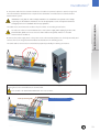
2. Disconnect connector J21 and short pins 1, 2 and 3 with a conductive connector.
UNUSED
5
4
3
2
1
3. Switch on DuraStation main breaker to supply power to the controller.
4. After a few seconds switch off DuraStation main breaker to remove power to the controller.
5. Remove the short and reconnect connector J21.
6. Switch on the DuraStation main breaker to supply power to the controller.
7. Reconfigure as desired via DuraStation controller configuration server interface. Refer to the description in
the earlier chapter.
Note: In the case of a network installation with RFID authentication, after a reset of the controller, the Station ID must
be modified to a new ID not previously used on this network to avoid any transaction data being lost.
7.6. Trouble shooting guide
www.gepowercontrols.com/eu/product_portfolio/GE_EV_charger/trouble-shooting.html
44
DuraStation™
Appendix
DuraStation settings for ID . . . . . . . . . . . . . . . . . . . . . . . . . . . . . . . . . . . . . . . . . . . . . . . . . . . . . .
Locality: . . . . . . . . . . . . . . . . . . . . . . . . . . . . . . . . . . . . . . . . . . . . . . . . . . . . . . . . . . . . . . . . . .
Unit Number: . . . . . . . . . . . . . . . . . . . . . . . . . . . . . . . . . . . . . . . . . . . . . . . . . . . . . . . . . . . . . . .
Installation instructions
Facility: . . . . . . . . . . . . . . . . . . . . . . . . . . . . . . . . . . . . . . . . . . . . . . . . . . . . . . . . . . . . . . . . . . .
Print one page for each DuraStation and keep this record in a safe location or inside the corresponding DuraStation.
* SAVE THESE INSTRUCTIONS*
The instructions do not purport to cover all details or variations in equipment nor to provide for every possible
contingency to be met in connection with installation, operation or maintenance. Should further information be
desired or should particular problems arise which are not covered sufficiently for the purchaser’s purposes,
the matter should be referred to the GE Company.
45
DuraStation™
EV Charging Station
Notes
46
.
.
.
.
.
.
.
.
.
.
.
.
.
.
.
.
.
.
.
.
.
.
.
.
.
.
.
.
.
.
.
.
.
.
.
.
.
.
.
.
.
.
.
.
.
.
.
.
.
.
.
.
.
.
.
.
.
.
.
.
.
.
.
.
.
.
.
.
.
.
.
.
.
.
.
.
.
.
.
.
.
.
.
.
.
.
.
.
.
.
.
.
.
.
.
.
.
.
.
.
.
.
.
.
.
.
.
.
.
.
.
.
.
.
.
.
.
.
.
.
.
.
.
.
.
.
.
.
.
.
.
.
.
.
.
.
.
.
.
.
.
.
.
.
.
.
.
.
.
.
.
.
.
.
.
.
.
.
.
.
.
.
.
.
.
.
.
.
.
.
.
.
.
.
.
.
.
.
.
.
.
.
.
.
.
.
.
.
.
.
.
.
.
.
.
.
.
.
.
.
.
.
.
.
.
.
.
.
.
.
.
.
.
.
.
.
.
.
.
.
.
.
.
.
.
.
.
.
.
.
.
.
.
.
.
.
.
.
.
.
.
.
.
.
.
.
.
.
.
.
.
.
.
.
.
.
.
.
.
.
.
.
.
.
.
.
.
.
.
.
.
.
.
.
.
.
.
.
.
.
.
.
.
.
.
.
.
.
.
.
.
.
.
.
.
.
.
.
.
.
.
.
.
.
.
.
.
.
.
.
.
.
.
.
.
.
.
.
.
.
.
.
.
.
.
.
.
.
.
.
.
.
.
.
.
.
.
.
.
.
.
.
.
.
.
.
.
.
.
.
.
.
.
.
.
.
.
.
.
.
.
.
.
.
.
.
.
.
.
.
.
.
.
.
.
.
.
.
.
.
.
.
.
.
.
.
.
.
.
.
.
.
.
.
.
.
.
.
.
.
.
.
.
.
.
.
.
.
.
.
.
.
.
.
.
.
.
.
.
.
.
.
.
.
.
.
.
.
.
.
.
.
.
.
.
.
.
.
.
.
.
.
.
.
.
.
.
.
.
.
.
.
.
.
.
.
.
.
.
.
.
.
.
.
.
.
.
.
.
.
.
.
.
.
.
.
.
.
.
.
.
.
.
.
.
.
.
.
.
.
.
.
.
.
.
.
.
.
.
.
.
.
.
.
.
.
.
.
.
.
.
.
.
.
.
.
.
.
.
.
.
.
.
.
.
.
.
.
.
.
.
.
.
.
.
.
.
.
.
.
.
.
.
.
.
.
.
.
.
.
.
.
.
.
.
.
.
.
.
.
.
.
.
.
.
.
.
.
.
.
.
.
.
.
.
.
.
.
.
.
.
.
.
.
.
.
.
.
.
.
.
.
.
.
.
.
.
.
.
.
.
.
.
.
.
.
.
.
.
.
.
.
.
.
.
.
.
.
.
.
.
.
.
.
.
.
.
.
.
.
.
.
.
.
.
.
.
.
.
.
.
.
.
.
.
.
.
.
.
.
.
.
.
.
.
.
.
.
.
.
.
.
.
.
.
.
.
.
.
.
.
.
.
.
.
.
.
.
.
.
.
.
.
.
.
.
.
.
.
.
.
.
.
.
.
.
.
.
.
.
.
.
.
.
.
.
.
.
.
.
.
.
.
.
.
.
.
.
.
.
.
.
.
.
.
.
.
.
.
.
.
.
.
.
.
.
.
.
.
.
.
.
.
.
.
.
.
.
.
.
.
.
.
.
.
.
.
.
.
.
.
.
.
.
.
.
.
.
.
.
.
.
.
.
.
.
.
.
.
.
.
.
.
.
.
.
.
.
.
.
.
.
.
.
.
.
.
.
.
.
.
.
.
.
.
.
.
.
.
.
.
.
.
.
.
.
.
.
.
.
.
.
.
.
.
.
.
.
.
.
.
.
.
.
.
.
.
.
.
.
.
.
.
.
.
.
.
.
.
.
.
.
.
.
.
.
.
.
.
.
.
.
.
.
.
.
.
.
.
.
.
.
.
.
.
.
.
.
.
.
.
.
.
.
.
.
.
.
.
.
.
.
.
.
.
.
.
.
.
.
.
.
.
.
.
.
.
.
.
.
.
.
.
.
.
.
.
.
.
.
.
.
.
.
.
.
.
.
.
.
.
.
.
.
.
.
.
.
.
.
.
.
.
.
.
.
.
.
.
.
.
.
.
.
.
.
.
.
.
.
.
.
.
.
.
.
.
.
.
.
.
.
.
.
.
.
.
.
.
.
.
.
.
.
.
.
.
.
.
.
.
.
.
.
.
.
.
.
.
.
.
.
.
.
.
.
.
.
.
.
.
.
.
.
.
.
.
.
.
.
.
.
.
.
.
.
.
.
.
.
.
.
.
.
.
.
.
.
.
.
.
.
.
.
.
.
.
.
.
.
.
.
.
.
.
.
.
.
.
.
.
.
.
.
.
.
.
.
.
.
.
.
.
.
.
.
.
.
.
.
.
.
.
.
.
.
.
.
.
.
.
.
.
.
.
.
.
.
.
.
.
.
.
.
.
.
.
.
.
.
.
.
.
.
.
.
.
.
.
.
.
.
.
.
.
.
.
.
.
.
.
.
.
.
.
.
.
.
.
.
.
.
.
.
.
.
.
.
.
.
.
.
.
.
.
.
.
.
.
.
.
.
.
.
.
.
.
.
.
.
.
.
.
.
.
.
.
.
.
.
.
.
.
.
.
.
.
.
.
.
.
.
.
.
.
.
.
.
.
.
.
.
.
.
.
.
.
.
.
.
.
.
.
.
.
.
.
.
.
.
.
.
.
.
.
.
.
.
.
.
.
.
.
.
.
.
.
.
.
.
.
.
.
.
.
.
.
.
.
.
.
.
.
.
.
.
.
.
.
.
.
.
.
.
.
.
.
.
.
.
.
.
.
.
.
.
.
.
.
.
.
.
.
.
.
.
.
.
.
.
.
.
.
.
.
.
.
.
.
.
.
.
.
.
.
.
.
.
.
.
.
.
.
.
.
.
.
.
.
.
.
.
.
.
.
.
.
.
.
.
.
.
.
.
.
.
.
.
.
.
.
.
.
.
.
.
.
.
.
.
.
.
.
.
.
.
.
.
.
.
.
.
.
.
.
.
.
.
.
.
.
.
.
.
.
.
.
.
.
.
.
.
.
.
.
.
.
.
.
.
.
.
.
.
.
.
.
.
.
.
.
.
.
.
.
.
.
.
.
.
.
.
.
.
.
.
.
.
.
.
.
.
.
.
.
.
.
.
.
.
.
.
.
.
.
.
.
.
.
.
.
.
.
.
.
.
.
.
.
.
.
.
.
.
.
.
.
.
.
.
.
.
.
.
.
.
.
.
.
.
.
.
.
.
.
.
.
.
.
.
.
.
.
.
.
.
.
.
.
.
.
.
.
.
.
.
.
.
.
.
.
.
.
.
.
.
.
.
.
.
.
.
.
.
.
.
.
.
.
.
.
.
.
.
.
.
.
.
.
.
.
.
.
.
.
.
.
.
.
.
.
.
.
.
.
.
.
.
.
.
.
.
.
.
.
.
.
.
.
.
.
.
.
.
.
.
.
.
.
.
.
.
.
.
.
.
.
.
.
.
.
.
.
.
.
.
.
.
.
.
.
.
.
.
.
.
.
.
.
.
.
.
.
.
.
.
.
.
.
.
.
.
.
.
.
.
.
.
.
.
.
.
.
.
.
.
.
.
.
.
.
.
.
.
.
.
.
.
.
.
.
.
.
.
.
.
.
.
.
.
.
.
.
.
.
.
.
.
.
.
.
.
.
.
.
.
.
.
.
.
.
.
.
.
.
.
.
.
.
.
.
.
.
.
.
.
.
.
.
.
.
.
.
.
.
.
.
.
.
.
.
.
.
.
.
.
.
.
.
.
.
.
.
.
.
.
.
.
.
.
.
.
.
.
.
.
.
.
.
.
.
.
.
.
.
.
.
.
.
.
.
.
.
.
.
.
.
.
.
.
.
.
.
.
.
.
.
.
.
.
.
.
.
.
.
.
.
.
.
.
.
.
.
.
.
.
.
.
.
.
.
.
.
.
.
.
.
.
.
.
.
.
.
.
.
.
.
.
.
.
.
.
.
.
.
.
.
.
.
.
.
.
.
.
.
.
.
.
.
.
.
.
.
.
.
.
.
.
.
.
.
.
.
.
.
.
.
.
.
.
.
.
.
.
.
.
.
.
.
.
.
.
.
.
.
.
.
.
.
.
.
.
.
.
.
.
.
.
.
.
.
.
.
.
.
.
.
.
.
.
.
.
.
.
.
.
.
.
.
.
.
.
.
.
.
.
.
.
.
.
.
.
.
.
.
.
.
.
.
.
.
.
.
.
.
.
.
.
.
.
.
.
.
.
.
.
.
.
.
.
.
.
.
.
.
.
.
.
.
.
.
.
.
.
.
.
.
.
.
.
.
.
.
.
.
.
.
.
.
.
.
.
.
.
.
.
.
.
.
.
.
.
.
.
103465
GE Energy
Industrial Solutions
Belgium
GE Industrial Belgium
Nieuwevaart 51
B-9000 Gent
Tel. +32 (0)9 265 21 11
Finland
GE Energy Industrial Solutions
Kuortaneenkatu 2
FI-00510 Helsinki
Tel. +358 (0)10 394 3760
France
GE Energy Industrial Solutions
Paris Nord 2
13, rue de la Perdrix
F-95958 Roissy CDG Cédex
Tel. +33 (0)800 912 816
Germany
GE Energy Industrial Solutions
Vor den Siebenburgen 2
D-50676 Köln
Tel. +49 (0)221 16539 - 0
Hungary
GE Hungary Kft .
Vaci ut 81-83.
H-1139 Budapest
Tel. +36 1 447 6050
Italy
GE Energy Industrial Solutions
Centro Direzionale Colleoni
Via Paracelso 16
Palazzo Andromeda B1
I-20041 Agrate Brianza (MB)
Tel. +39 2 61 773 1
Netherlands
GE Energy Industrial Solutions
Parallelweg 10
Nl-7482 CA Haaksbergen
Tel. +31 (0)53 573 03 03
Poland
GE Power Controls
Ul. Odrowaza 15
03-310 Warszawa
Tel. +48 22 519 76 00
Portugal
GE Energy Industrial Solutions
Rua Camilo Castelo Branco, 805
Apartado 2770
4401-601 Vila Nova de Gaia
Tel. +351 22 374 60 00
Russia
GE Energy Industrial Solutions
27/8, Electrozavodskaya street
Moscow, 107023
Tel. +7 495 937 11 11
South Africa
GE Energy Industrial Solutions
Unit 4, 130 Gazelle Avenue
Corporate Park Midrand 1685
P.O. Box 76672 Wendywood 2144
Tel. +27 11 238 3000
Spain
GE Energy Industrial Solutions
P.I. Clot del Tufau, s/n
E-08295 Sant Vicenç de Castellet
Tel. +34 900 993 625
United Arab Emirates
GE Energy Industrial Solutions
1101, City Tower 2, Sheikh Zayed Road
P.O. Box 11549, Dubai
Tel. +971 43131202
United Kingdom
GE Energy Industrial Solutions
Houghton Centre
Salthouse Road
Blackmills
Northampton
NN4 7EX
Tel. +44 (0)800 587 1239
@
www.ge.com/ex/industrialsolutions
www.ge.com/uk/industrialsolutions
GE imagination at work
Ref. E/5407/E/EX Ed. 12/11
© Copyright GE Industrial Solutions 2011