1
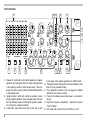
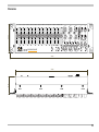
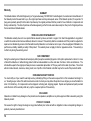
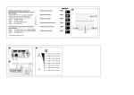
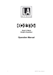
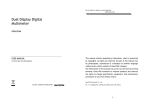
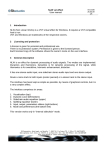
PE137 1/3 OCTAVE PARAGRAPHIC EQUALISER USER MANUAL +1 0 1 1 3 5 5 8 +1 0 +1 N AI -12 G 0 8 +3 IP 3 CL dB 12 3 5 N 6 Y 8 dB -3 9 +1 3 12 D +6 0 0 W +3 12 LO ISE 5 HF K 15 NO H 6 22 S K E R 18 dB 8 TE 10 A 21 . FIL. D B K IG -3 dB ING/OCT 30 R 2d S 1 6 + + LV dB O 5K F SHE 6 O IN L z 8 A T M 0 KH -12 G -6 OU 18 12 40 4 90 6 -00 LP X 0 A IN M 23 2K 40 8 3 B 2d 0 1 -2 -1 0 +1 3 5 8 1 3 5 3 5 -1 8 3 0 3 5 -1 5 8 +1 N AI -12 G 0 B 2d 8 +3 IP 3 CL dB 12 3 5 N 6 Y 8 dB -3 9 +1 3 12 D +6 0 0 W +3 12 LO ISE 5 -2 -1 HF K 15 NO H 6 22 S K E R 18 dB 8 TE 10 A 4 3 21 . FIL. D B K IG -3 dB ING/OCT 30 R 2d S 1 6 + + LV dB 5 O 5K 7 F SHE 6 O IN L z 8 A T M 0 KH -12 G -6 OU 18 12 40 4 90 6 -00 LP X 0 A IN M 23 2K 40 2 Thank you for choosing this PE series paragraphic equaliser for your application. You have made an excellent choice. This PE series paragraphic equaliser is designed and built to be the most versatile analog graphic plus parametric processor available. The combination of a full featured graphic and parametric equaliser with high and low pass and shelving filters provides full control to even the most exacting user. The dynamics trim control and the 8 segment level/peak meter provide headroom optimisation of the signal path. This unique feature makes it possible to reduce the noise floor of the unit by as much as 12dB, making the equaliser virtually dissapear in critical applications. If a higher noise floor is acceptable, this control can create an extra 12dB of headroom for the filter circuits, thereby minimising distortion and clipping. The autoranging power supply of the PE series guarantees trouble free operation of this unit all over the world, independent on local mains conditions. You probably want to start working with this new equipment right away and not read all of the information inside this manual. For those of you who are in a hurry, please read the safety instructions carefully. Also the information about the DYN control, a unique feature of the Q4audio equalisers, will be very enlighting. Summit Engineering nv Q4audio division Tongersesteenweg 190 3800 Sint Truiden Belgium tel: +32 11 69 42 59 fax: +32 11 69 45 92 www.Q4audio.com email: [email protected] SE Part Number: 17000-00051 Rev. A Q4audio is a registered trademark of Summit Engineering nv All other trademarks are property of their respective owners 3 Explanation of grahical symbols: ! This symbol is intended to alert the user of presence of uninsulated dangerous voltage within the products enclosure that may be of sufficient magnitude to constitute risk of electric shock to persons. This symbol is intended to alert the user of presence of important operating and maintenance (servicing) instructions in the literature accompanying the appliance. Explication des symboles graphiques: Ce symbole doit alerter lutilisateur du danger provenant dun voltage dangereux et non protégé à lintérieur de lappareil, voltage suffisamment fort pour représenter un danger réel délectrocution. ! Ce symbole doit attirer lattention de lutilisateur sur les instructions importantes qui concernent le service et la maintenance et qui accompagnent tout appareil. Erklärung der Bildsymbole: Dieses Symbol warnt den Benutzer vor nicht isolierter gefährlicher Spannung im Inneren des Gerätes. Diese Spannung ist hoch genug um Personen durch elektrischen Schlag zu gefährden. ! Note: Dieses Symbol weist den Benutzer auf wichtige Bedienungs- und Wartungsanweisungen hin die in den gerätebegleitenden Unterlagen aufgeführt werden. This equipment has been tested and found to comply with EN551031 and EN55103-2 product specifications. These product specifications are designed to provide a reasonable protection against harmful interference. This equipment generates, uses and can radiate radio frequency energy and, if not installed and used in accordance with instructions, can cause harmful interference. There is no guarantee that interference will not occur in a specific installation. If harmful interference is detected try and correct it by one of the following measures: Increase the separation between the equipment. Connect the equipment to different mains outlets. Reroute cables. 4 CAUTION RISK OF ELECTRIC SHOCK DO NOT OPEN ! CAUTION: To reduce the risk of electric shoc, do not open. No user-serviceable parts inside. Refer servicing to qualified personnel. WARNING: To prevent fire or electric shoc, do not expose this equipment to rain or moisture. ATTENTION RISQUE DE CHOC ELECTRIQUE NE PAS OUVRIR ! ATTENTION: Pour éviter les risques de choc électrique, ne pas ouvrir. Cet appareil ne comporte aucune pièce pouvant être réparée par lutilisateur. Confier lentretien à un technicien qualifié. AVERTISSEMENT: Pour éviter les risques de choc électrique ou dincendie, nexposez cet appareil ni à lhumidité ni à leau (pluie...). ACHTUNG GEFAR FUR ELEKTRISCHEN SCHLAG GERÄT NICHT ÖFFNEN ! ACHTUNG: Um Gefährdung durch elektrischen Schlag zu vermeiden darf das Gerät nicht geöffnet werden. Es befinden sich keine vom Benutzer reparierbaren Teile im inneren des Gerätes.Jegliche Reparatur soll einem qualifizierten Fachmann uberlassen werden. WARNUNG: Um die Gefahr eines Feuers bzw. eine Verletzung durch elektrischen Schlag zu vermeiden sollte das Gerät niemals Regen oder Feuchtigkeit ausgesetzt werden. Safety Instructions 1. Read Instructions - All safety and operating instructions should be read before this unit is put into service. 2. Keep instructions - The safety and operating instructions should be retained for future reference. 3. Observe Warnings - All warnings on the unit and in this operating manual should be strictly followed. 4. Water and Moisture - This unit should not be used near water - for example, near bathtub, washbowl, kitchen-sink, laundry tub, in a wet basement, near a swimming pool or the like. 5. Heat - This unit should be placed away from heat sources, such as radiators or other devices which produce heat. 6. Power cord protection - The power supply cord should be routed so that it is not likely to be stepped on or pinched by objects placed on or against them. 7. Non-use periods - The power cord of the unit should be unplugged from the outlet when the unit is not used for a longer period. 8. Object and liquid entry - Care should be taken so that objects do not fall and liquids are not spilled into the inside of the unit. 9. Damage requiring service - Unplug the unit and refer servicing to qualified service personnel under any of the following conditions: beyond those means described in this operating manual. All other servicing should be referred to qualified personnel. 11. To prevent fire or electric shock - Only use the polarised mains plug option together with a polarised receptacle. This unit is equipped with a single pole disconnect device (fuse) in the phase (live) wire. If an unpolarised mains connection is used the receptacle the unit is connected to must be equipped with a two pole disconnect device (fuse) of appropriate rating. 12. Grounding and mains polarisation - Precautions should be taken so that the grounding and mains polarisation means of the unit are not defeated. 13. Ventilation - Slots and openings in the unit are provided for ventilation, to ensure reliable operation and to prevent overheating of the unit. These openings should not be blocked or covered! Objects have fallen, or liquid has been spilled into the unit. The unit has been exposed to rain. The unit does not appear to operate normally or exhibits a marked change in performance. The unit has been dropped, or its chassis damaged. The power cord or plug is damaged. 10. Servicing - The user should not attempt to service the unit 5 The Front Panel 17 4K 5K 6K3 16 15 8K 10K 12K5 16K 20K Hz +6 dB -2 -1 4 0 +1 3 3 12 8 8 5 7 5 +3 0 -3 3 12 8 8 6 0.5 Q x0.1 x1 -6 dB 2 0 -5 BYPASS ALL 1 GRAPHIC SECTION PARAMETRIC SECTION 250 ON 6 dB SCALE ON 2 3 4 Q x0.1 FREQ. -5 0.5 Q x0.1 FREQ. 2000 Hz 5 -6 MEASURING POINT 0 x1 +5 MAX 8 x10 40 -5 FREQ. 12 11 -6 HF +6 dB LF +6 dB SHELVING FILTERS 6dB/OCT. 90 10K 5K 22K 180 +5 230 20 +10 -10 % 1600 170 18 OUT IN 700 1. Bypass All switch with control led to bypass the complete equaliser. By pressing this knob, the input is directly linked to the output by means of a the fail-safe relay. When the power to the unit is removed, the unit automatically switches to this bypass mode. 2. Graphic section switch with control led enables or disables the graphic equaliser. Even in bypass mode, the level and clip detection keeps monitoring the graphic equalisers circuitry for overload conditions. 3. 6 dB scale switch with control led to alter the cut and 6 3 0 6 +10 -10 % 1600 250 170 H E A D R O O M 4 2 700 2000 Hz 5 +12 dB -12 -00 GAIN 8 x1 +5 +10 -10 % 1600 250 170 8 NOTCH x10 700 12 8 13 0 0 1 +1 1 -1 CLIP 3 3 3 3 3 5 5 5 6 5 9 8 8 8 8 12 +12 dB -12 15 LOW12 DYN 12 dB GAIN 18 NOISE 0 0 21 dB SIG. -3 +3 -3 +3 +1 3 6 0.5 0 3 7 5 4 2 8 -2 -1 4 5 NOTCH x10 +1 +12 dB -12 -00 GAIN 4 2 1 0 3 7 5 +12 dB -12 -00 GAIN NOTCH -2 -1 4 14 2000 Hz 12dB/OCT. POWER 6 30K 15 HP 300 Hz 2K LP 40K Hz CUT FILTERS 7 ON ON 8 9 10 boost range of the graphic equaliser from 12dB to 6 dB. 4. Parametric section switch with control led enables or disables the three parametric filters. 5. Three parametric sections. See next pages for detailed information about these controls. 6. Power led indicates when mains power is connected to the unit. 7. High Pass frequency adjustment. Adjustment range is 15Hz* to 300Hz*. 8. HP switch with control led to turn HP filter on or off. 9. LP switch with control led to turn LP filter on or off. 10. Low Pass frequency adjustment. Range is 2KHz* to 40KHz*. 11.High Frequency Shelving filter control. Enables tilting the high frequency range by ±6dB. 12.Low Frequency Shelving filter control. Enables tilting the low frequency range by ±6db. 13. Gain control knob to adjust overall gain between -12dB and +12dB. 14. Dynamics control knob. This control enables levelling of the signal inside the equaliser. By turning the control anticlockwise (low noise position) the signal is amplified at the input and attenuated at the output. This increases the signal level in the equaliser electronic circuits and improves the signal to noise ratio by as much as 12dB. Use the headroom indicator as a read-out of the maximum signal level in the units circuits to adjust this control. Turning the DYN control clockwise will reduce the input gain and at the same time increase output gain, to keep overall gain constant. As a consequence, the input signal level to the filters is lowered, giving more headroom at the expense of an increased noise floor. Because the headroom indicator measures signal level at every critical point in the equaliser, therefore also at the output, turning the DYN control clockwise will not always show up on the headroom indicator. Reason is that the output level remains the same and decreasing the signal level in circuits that precede the output is not sensed by the headroom indicator. The true virtue of the clockwise DYN range becomes apparent when some filters in the unit are masked by others. For instance, when the shelving controls are used to boost a range of frequencies while the graphic equaliser is used to cut a specific range of these frequencies. In such case it can be important to reduce the signal level in the shelving filters to accommodate the boost and avoid clipping of the these filters. In this case the gain in headroom is clearly indicated by the level meter because the measuring point at the shelving filters in not masked by the output measuring point because the graphic equaliser that follows the shelving filters in the signal path, attenuates the output level. Changing the DYN control position does not change overall gain of the unit (smaller than ±0.5dB of overall gain change over the entire control range). 15. Headroom meter and a clip indicator. The headroom indicator is an average calibrated peak meter that indicates headroom in dB from clipping level. The clip led lights at +20dBu (0 dBu is 0.7746V). The absolute overload point of the unit is at +21dBu. The clip led gives accurate indication of overload conditions inside the unit, independent of the measuring point switch position. 16. Measuring point switch selects monitoring of input, output or maximum signal level. During operation the switch should be in the MAX position, indicating the maximum signal level of all possible overload points inside the unit. Time constants are chosen for easy read-out and comfortable adjustment of the DYN control. The INPUT and OUT positions enable overall gain adjustment of the unit and should only be used temporarily while adjusting the equaliser. Response time of the display is very fast in this mode to avoid delay. 17. Sliders to cut or boost the individual 1/3 octave frequencies of the graphic equaliser. 18. Four M4 screws fix the 19" bracket ornamental parts. In case a security cover is mounted, these mounting positions are used to fix the security cover. 7 Parametric Sections -2 -1 4 0 +1 3 3 12 8 8 6 5 7 5 +12 dB -12 -00 GAIN 5 4 NOTCH 2 4 1 Q = fc / Bw 6 0.5 Q x0.1 0 x1 -5 +5 700 1 In reciprocal mode the -3dB frequencies are measured relative to the maximum cut or boost setting. In notch mode the 3dB bandwidth is referenced to 0dB (flat response). 8 x10 2 3 15.00 +10 -10 % 1600 250 170 FREQ. 2000 Hz Each of the 3 parametric sections of the PE137 operates independantly of the others and allows the setting of a fully adaptable boost, cut or notch filter anywhere in the audio spectrum. 1. The coarse frequency control allows the setting of the filter center frequency. For fine tuning the frequency, use the vernier control (3). 2. The range switch sets the range in which the frequency control operates. The audio spectrum is divided into 3 overlapping ranges: 17-200Hz, 170-2KHz and 1.7-20KHz. 8 3. Frequency vernier control allows fine tuning of the center frequency over a ±10% range. Normal procedure is to start frequency adjustment with the vernier control in the center (0%) position, making coarse adjustments with the frequency control and then fine tuning the center frequency with the vernier control. 4. The Q control adjusts the filter bandwidth. Q is defined as the ratio of filter center frequency to filter bandwidth: 0.0 -15.00 fc Bw 5. The cut mode switch allows selection of notch (down position) or reciprocal (up position) filter response. In reciprocal mode the cut response has the same form factor as the boost response. In this mode two cascaded filters with the same alignment (center frequency and Q) of which one boosts a certain number of dBs while the other cuts that same amount will perfectly compensate each other because both the gain and the phase responses are perfectly complementary. 6. The gain control adjusts the amount of cut or boost. The center detent position completely bypasses the filter, thereby guaranteeing perfectly flat response, independant on component tolerances. * Note: Although high quality carbon polymer potentiometers are used in this unit, absolute calibration accuracy of these controls is only modest. Indicated values on the front panel represent average numbers collected from several production lots. Actual values can differ by as much as 20% from the indicated values. Remark: The figure below shows the response of the parametric filter in reciprocal and notch response. It is clear that notch response is far superior to reciprocal cut response for eliminating smallband noise or feedback problems. Only a very small frequency band around the center frequency is affected by the filter. AUDIO P R E C IS ION 15.000 AMP L (dB u) vs F R E Q(Hz) 0.0 -15.00 -30.00 -45.00 -60.00 200 1k 5k 9 The Rear Panel www.Q4audio.com Q4audio IS A PRODUCT OF SUMMIT ENGINEERING NV MADE IN BELGIUM, EU Model: PE 137 WARNING: TO REDUCE THE RISK OF FIRE OR ELECTRIC SHOCK DO NOT EXPOSE THIS EQUIPMENT TO RAIN OR MOISTURE. NO USER SERVICEABLE PARTS INSIDE. REFER SERVICING TO QUALIFIED PERSONNEL. READ INSTRUCTION MANUAL CAREFULLY BEFORE USE. Serialnr.: PE137-01AA-0001 Date of manufacture: 05.11 .02 ATTACH TYPE LABEL TO THIS LOCATION. THIS Made in Belgium, EU CONTAINS IMPORTANT SAFETY LABEL INFORMATION AND MUST NOT BE REMOVED. Power requirements: 85-264V 12W REPLACE LABEL IN AC CASE50/60Hz IT GOT DAMAGED FUSE: T 315 mAOR/ LOST. 250 V ATTENTION: AFIN DE REDUIRE LE RISQUE DE CHOC ELECTRIQUE, NE PAS EXPOSER A LA PLUIE NI A L'HUMIDITE. INPUT IMPEDANCE: 20K BALANCED 10K UNBALANCED INPUT GND 1 2 + 3 OUTPUT OUTPUT IMPEDANCE: 100 OHM BALANCED 50 OHM UNBALANCED NOTICE: SYSTEM CONNECTOR USES PROPRIETARY FORMAT. REFER TO USER MANUAL BEFORE MAKING CONNECTIONS. SYSTEM CONNECTOR AVIS CAUTION RISQUE DE CHOC ELECTRIQUE NE PAS OUVRIR RISK OF ELECTRIC SHOCK DO NOT OPEN ! MAINS INPUT CAUTION: FOR CONTINUED PROTECTION AGAINST FIRE HAZARD REPLACE ONLY WITH SAME FUSE TYPE AND RATING. REFER TO TYPE LABEL FOR FUSE RATING. ATTENTION: AFIN D'ASSURER UNE PROTECTION PERMANENTE CONTRE LES RISQUES D'INCENDIE REMPLECEZ UNIQUEMENT PAR UN FUSIBLE DE MEME TYPE ET VALEUR. CONSULTEZ LA PLAQUE DE MARQUAGE. 1 10 2 5 CLASS 1 EQUIPMENT. MUST BE EARTHED! LINE: 85-264V / 50-60Hz 3 4 1. Balanced input XLR-3. The input impedance is 20K Ohm balanced or 10K unbalanced. Each input leg has the same impedance to ground to maximise input common mode rejection ratio, independent of source impedance. The maximum overload level of the input circuitry is +21dBu. Pin 1 of the input connector is connected to chassis ground. Pin 2 is the non-inverting (positive,) pin 3 the inverting (negative) input, conform international standards. 2. Balanced output XLR -3. The output impedance is 100 Ohm balanced or 50 Ohm unbalanced. The output can drive +21dBu into 600 Ohm with low distortion. Pin 1 is connected to chassis ground. Pin 2 is the non-inverting (positive,) pin 3 the inverting (negative) input, conform international standards. 3. Mains inlet and fuseholder. The mains connector is a standard 3 pin IEC connector. The centre terminal is directly connected to the chassis of the unit and must be connected to the earth terminal of the mains outlet. This is important for your safety. The mains cable supplied with this unit is a universal European model. Use only the polarised mains plug option together with a polarised receptacle. This unit is equipped with a single pole disconnect device (fuse) in the phase wire. If an unpolarised mains connection is used the receptacle the unit is connected to must be equipped with a two pole disconnect device (fuse) of appropriate rating. In case the mains plug on the mains cable is not conform to your local standard, you will need to replace it with a suitable one. In this case it is very important to respect the colour coding of the wires: The mains fuse is a standard 5x20mm fuse. Rating is indicated on the type label on the back of the unit. The fuse drawer can easily be opened with a flat tip screwdriver. For safety reasons, the mains cable must be removed before the drawer can be opened. Replace only with the same fuse type and rating. The auto-ranging power supply of the GE series guarantees trouble free operation all over the world, independent of local mains conditions. Acceptable mains voltages are in the range from 85 to 264 Vrms 50/60Hz. When mains power is removed, the unit automatically switches to the bypass mode, hardware linking the input to the output by means of the fail-safe relay. 4. The screws on both sides of the mains inlet are essential for the safety of the unit. These screws connect the earth pin of the mains connector to the chassis. These screws must be well tightened at all times. 5. 15 pin SubD system connector. This connector integrates the PE137 in the optional Q4audio equaliser drawer. The system connector can also be used to monitor and control the unit remotely in installations. See next page for layout and pinning of the system connector. yellow/green : earth ground brown or black : phase (live) blue : neutral 11 P IN 8 15 5 6 7 14 13 3 4 12 11 1 2 10 9 System connector layout and pinning information 12 FU N C TION D E S C R IP TION 1 GND A UD IO GROUND 9 IN+ NON INV E RTING A UD IO INP UT 2 IN- INV E RTING A UD IO INP UT 10 GND A UD IO GROUND 3 GND A UD IO GROUND 11 OUT+ NON INV E RTING A UD IO OUTP UT 4 OUT- INV E RTING A UD IO OUTP UT 12 GND A UD IO GROUND 5 GND A UD IO GROUND 13 -15V -15V S UP P LY V OLTA GE MA X C URRE NT 50mA . 6 +15V +15V S UP P LY V OLTA GE MA X C URRE NT 50mA . 14 OV LLE D P IN V OLTA GE S WITC HE S FROM +15V TO -15V IN C A S E OF OV E RLOA D . THE V E NIN IMP E D A NC E 3.3K . MA X C URRE NT 10mA . 7 A C TIV E RE FE RE NC E D TO +15V. S INK S A P P. 10mA WHE N UNIT IS A C TIV E . 15 RE M OFF C ONNE C TING THIS P IN TO GROUND OR -15V P UTS THE UNIT IN B YPA S S MOD E . 8 GND S YS TE M GROUND RE TURN Dimensions 88,90 25 31 40 50 63 80 100 125 160 200 250 315 400 500 630 800 1K 1K25 1K6 2K 2K5 3K15 4K 5K 6K3 8K 10K 12K5 16K 20K Hz +12 dB +9 +6 +3 +1 0 -1 -3 -6 -9 -12 dB +6 dB -2 -1 4 0 +1 3 5 -3 1 6 0.5 Q 2 0 x1 -5 x10 x0.1 BYPASS ALL PE137 PARAGRAPHIC EQUALISER GRAPHIC SECTION ON 6 dB SCALE PARAMETRIC SECTION 250 ON 170 FREQ. 3 -5 2000 Hz 6 0.5 Q x10 x0.1 FREQ. FREQ. 8 12 40 -5 0 3 5 8 8 12 dB +1 3 5 -12 +12 dB GAIN 0 +3 -3 +3 -6 HF +6 dB LF +6 dB SHELVING FILTERS 6dB/OCT. 10K 90 5K 22K 180 +5 230 20 +10 -10 % 1600 170 -1 5 -6 MEASURING POINT 700 2000 Hz 1 3 0 x1 0 OUT MAX 8 1 15 LOW DYN 18 NOISE 0 21 dB SIG. -3 IN +10 -10 % 1600 250 170 H E A D R O O M 4 +5 700 +10 -10 % 1600 250 8 2 0 x1 +5 700 5 NOTCH 8 CLIP 3 3 6 5 9 8 12 3 +12 dB -12 -00 GAIN 6 Q +1 12 8 4 0.5 0 3 7 5 8 2 8 x10 x0.1 -6 dB 5 NOTCH 2 -2 -1 4 3 +12 dB -12 -00 GAIN 4 NOTCH +1 12 8 +12 dB -12 -00 GAIN 0 0 3 7 5 8 12 8 +3 -2 -1 4 3 7 5 2000 Hz POWER 30K 15 HP 300 Hz 2K LP 40K Hz CUT FILTERS 12dB/OCT. ON ON 482,60 55,00 420,00 13 Specifications Input: Type: Electronically balanced. Transformer balancing optional. Input impedance:10KOhm. Equal impedance for + and - legs. Maximum input level: +21dBu. Input connector: XLR-3F Pin 1 Floating Pin 2 Signal + (hot) Pin 3 Signal - (cold) Output: Type: Electronically balanced and floating, simulating transformer output. Active transformer balancing optional. Output impedance: 100 Ohms / 50 Ohms each leg. Maximum output level: +21dBu into 600 Ohms or greater. Output connector: XLR-3M Pin 1 Ground Pin 2 Signal + (hot) Pin 3 Signal - (cold) General performance: Frequency response: ±0.5dB, 20Hz-20KHz (all controls flat). THD: <0.005%, 20Hz-20KHz. Noise: <-93dBu, 22Hz-22KHz unweighted, graphic equaliser in circuit 0dB settings. Level meter display: 8 led average calibrated peak responding headroom indication in 3dB steps. Clip led lights for approximately 200ms if the instantaneous peak voltage at any potential overload point in the unit comes within 1 dB of clipping, independent of level display routing switch position. Dynamics control: Continuously variable ±12dB of gain shift lowers noise floor by 12dB or increases headroom by 12dB. Changing the DYN control settings will change overall gain of the unit by no more than ±0.5dB (±0.3dB typical). 14 Filters: Graphic equaliser: 30 near ISO centre frequencies 25Hz20KHz 1/3 octave. Graphic filters centre frequency tolerance < 5%. Max boost/cut: switcheable 6 or 12dB ±0.5dB reciprocal. Graphic equaliser switcheable in/out of signal path. High pass filter: 15Hz-300Hz frequency range. Butterworth maximally flat 12dB/octave response. Switcheable in/out of signal path. Low pass filter: 2KHz-40KHz frequency range. Butterworth maximally flat 12dB/octave response. Switcheable in/out of signal path. Shelving filters: 6dB of boost and cut at 100Hz and 14KHz. 6dB/octave slope. Parametric filter sections (3 of): Gain control: ±12dB ±0.5dB cut or boost range in reciprocal mode. Notch depth typically 50dB at 1KHz and average Q setting. Q-factor continuously variable between 0.5 and 8. Frequency continuously variable from 17Hz to 20KHz in 3 ranges. Frequency vernier ±10% of main frequency control. The group of parametric filters is switcheable in/out of the signal path. Power requirements Voltage: 85V-264V 50/60Hz. Consumption: 15VA. Connector: IEC 3 pin. Dimensions: 420mm (482.6mm with 19" mounting brackets) wide x 88.9mm high x 55mm deep. Weight: Shipping: 3.1kg; Net: 2.4 kg. Standards: Safety: EN60065 EMC: EN55103-1/EN55103-2/E2/E3 Note: Although high quality carbon polymer potentiometers are used in this unit, absolute calibration accuracy of these controls is only modest. Indicated values on the front panel represent average numbers collected from several production lots. Actual values can differ by as much as 20% from the indicated values. In keeping with our policy of continued improvement, Q4audio reserves the right to change features and specifications without prior notice. 15 Warranty SUMMARY The Q4audio division of Summit Engineering nv Tongersesteenweg 190 3800 Sint-Truiden Belgium, the creators and manufacturers of the Q4audio product line warrants to you, the original purchaser and any subsequent owner of this Q4audio product, for a period of 2 (two) years (warranty period) from the date of purchase by the original purchaser that the product is free of defects in components and factory workmanship. The date of purchase is the date appearing on the first end-users sales receipt or other proof of original purchase from an authorised Q4audio dealer. ITEMS EXCLUDED FROM WARRANTY This Q4audio warranty does not cover product failure caused by misuse, accident or neglect. Nor shall it be applicable to any product on which the serial number has been defaced, altered or removed. This warranty shall be considered void if this product is subjected to repair work or alteration by persons other than authorised by Q4audio in such a manner as to injure, in the sole judgment of Q4audio, the performance, stability, reliability or safety of this product. This warranty does not apply to finish or appearance items. This warranty is in effect only during the warranty period. OUR COMMITMENT During the warranty period, Q4audio will remedy any defect (except as excluded) by repair or at its option replacement or refund. In case of refund the defective or malfunctioning product shall be made available to us free and clear of all lies or other encumbrances. The refund will be equal to the original purchase price less a reasonable depreciation of 10% per year from the date of purchase. The refund will not include interests, insurance, closing costs, loss of profit or other financial costs that may be the result of the products defect. OBTAINING WARRANTY SERVICE You must notify us of your need for warranty service, preferably by filling out the service request form in this manual and returning it to us. We will give you notice of the authorised service center to whom you may deliver the product or we will give you an authorisation to return it to the factory. All components must be shipped in a factory pack, shipping prepaid. Repairs and replacement parts provided under the terms of this warranty shall carry only the unexpired portion of this warranty. DISCLAIMER Q4audio is not liable for any damage to other products such as speakers, amplifiers or any other equipment that is caused by using this Q4audio product. PRODUCT CHANGES We reserve the right to change the design on any product without prior notice and with no obligation to make corresponding changes in products previously manufactured. 16