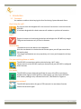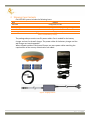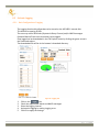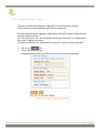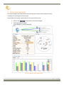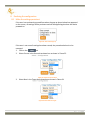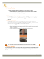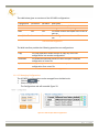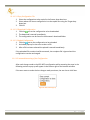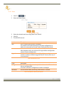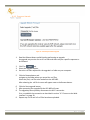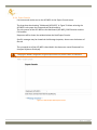
1
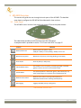
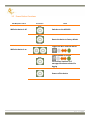
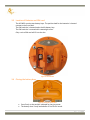
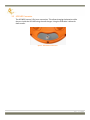
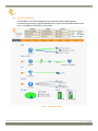
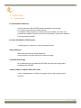
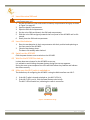
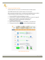
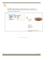
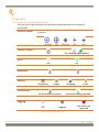
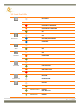
APS-NR2 User Manual Revision 1.0.0 APS-NR2 User Manual © 2014 ALTUS Positioning Systems Inc. All rights reserved. ALTUS and the ALTUS logo are trademarks of ALTUS Positioning Systems Inc. registered in the U.S. and other countries. No part of this document may be copied, used or reproduced without the prior written permission of ALTUS Positioning Systems. No part of this manual me by reproduced or transmitted in any form or by any means, electronic or mechanical, including photocopying and recording, or any purpose without the express written permission of ALTUS Positioning Systems Inc. Mention of third-party products in this document is for informational purposes only and does not constitute an endorsement or a recommendation. ALTUS Positioning Systems assumes no responsibility with regard to the performance or use of the APS-NR2 due to GNSS characteristics, USA Department of Defense operations control, atmospheric effects, multipath and RF interference. All understandings, agreements, or warranties take place directly between the seller and the prospective users. Every effort has been made to ensure that the information in this manual is accurate. ALTUS is not responsible for printing or clerical errors. All specifications are typical and subject to change without prior notice. 1 | Page Table of Contents 1 Introduction....................................................................................... 4 1.1 1.2 1.3 1.4 1.5 1.6 1.7 1.8 1.9 1.10 Foreword .......................................................................................................................... 4 APS-NR2 Technical Characteristics ................................................................................... 5 User Notice ....................................................................................................................... 6 Warranty .......................................................................................................................... 6 Technical Support ............................................................................................................. 7 CE NOTICE......................................................................................................................... 8 ROHS/WEEE NOTICE......................................................................................................... 8 FCC Regulations ................................................................................................................ 9 IC Regulations ................................................................................................................. 10 Safety Information ......................................................................................................... 11 2 Shipping Case Contents ................................................................... 12 3 APS-NR2 Overview........................................................................... 13 3.1 3.2 3.3 3.4 3.5 3.6 Front Panel ..................................................................................................................... 13 Power Button Functions ................................................................................................. 14 Location of Batteries and SIM card ................................................................................ 15 Closing the battery door ................................................................................................ 15 APS-NR2 Connector ........................................................................................................ 16 The Web Interface .......................................................................................................... 17 4 Initial set up ..................................................................................... 18 4.1 4.2 4.3 4.4 4.5 4.6 4.7 Prerequisites................................................................................................................... 18 Insert the micro SIM card ............................................................................................... 19 Insert the batteries......................................................................................................... 19 Switch on the APS-NR2................................................................................................... 19 Wait for the APS-NR2 to start up ................................................................................... 19 Make sure the Wi-Fi radio is switched on ...................................................................... 19 Connect to the Web Interface........................................................................................ 20 5 Basic Configuration of the APS-NR2 for RTK .................................... 21 5.1 5.2 5.3 Set up the cellular modem ............................................................................................. 22 Configure as NTRIP client ............................................................................................... 24 APS-NR2 Configured for RTK .......................................................................................... 26 6 Configuring the output .................................................................... 27 6.1 6.2 Connect Bluetooth ......................................................................................................... 27 Configure the NMEA for Bluetooth output .................................................................... 28 2 | Page 6.3 Activate Logging ............................................................................................................. 29 7 Set the Antenna Height ................................................................... 31 8 Finalizing the configuration ............................................................. 32 8.1 8.2 Make the settings persistent.......................................................................................... 32 Switch off Wi-Fi .............................................................................................................. 33 9 Retrieving the collected data from the receiver .............................. 34 9.1 9.2 Using the Web Interface ................................................................................................ 34 Using the USB connection .............................................................................................. 35 10 Hot Swapping the batteries and charging ........................................ 37 10.1 Battery Swapping ........................................................................................................... 37 10.2 Battery Charging............................................................................................................. 38 11 System Administration using the Web Interface ............................. 39 12 Appendix ......................................................................................... 46 12.1 12.2 12.3 12.4 12.5 Status Icons on the Web Interface ................................................................................. 46 Front Panel LEDs............................................................................................................. 47 The batteries .................................................................................................................. 48 Cell modem Commands ................................................................................................. 49 List of Typical GNSS Related Acronyms .......................................................................... 50 3 | Page 1 Introduction 1.1 Foreword You made an excellent choice buying the Altus Positioning Systems Network Rover. Don’t drop the call! Do not lose time with dropped calls. Your source of corrections is most secure with APS-NR2. It has been designed with a dual antennae cell modem to optimize call retention. Light Despite its smarts on board and the wireless technologies the APS-NR2 only weighs 760 grams and measures only 167mm in diameter. Work all day The batteries of the APS-NR2 are hot swappable. With the two batteries in the device and the two spares you will span more than a full working day! The charger and batteries are non proprietary so it is easy and inexpensive to keep spares. Use your existing phone or tablet The APS-NR2 communicates with any device having a Wi-Fi radio. Simply connect to the APS-NR2, open your browser and your APS-NR2 is configured within minutes. Esri ready The APS-NR2 has been designed specifically for users of ArcGIS to enrich their database with highly accurate positions. Alternatively you may use the APS-NR2 with industry leading survey software like SurvCE, Field Genius or Digiterra. Works in any network The APS-NR2 works within all types of RTK networks. Its auto detect function selects the correction type! 4 | Page 1.2 APS-NR2 Technical Characteristics The APS-NR2 provides multi-frequency GNSS capability and wireless communications. a Septentrio AsteRx-m GNSS receiver inside. Fully wireless operations via Wi-Fi, Bluetooth and Cell networks. Intuitive device-independent graphical web-interface. Four Li-Ion hot-swappable batteries. 8GB memory for internal data logging. 1.2.1 GNSS Key Features 136 Channel AsteRx-m, with L1/L2/L2C GPS, GLONASS and SBAS. RTK, SBAS, DGPS and Standalone positioning modes. Navigation Performance Standalone (Autonomous) SBAS (WAAS, EGNOS, MSAS) DGPS (RTCM1,3 / 9,3) RTK (Fixed) Horizontal (m) 1.3 0.6 0.5 0.006 + 0.5 ppm Vertical (m) 1.9 0.8 0.9 0.01 + 1 ppm Table 1: APS-NR2 Facts & Figures The APS-NR2 can be mounted on a standard survey rod with a 5/8" thread. 5 | Page 1.3 User Notice This section provides information regarding Warranty and Customer Service. ALTUS Positioning Systems reserves the right for improvements and changes to this document, products and services without notice or obligation. 1.4 Warranty ALTUS provides a two-year warranty for the APS-NR2 receiver, free from defects in materials and workmanship, from the date of sale on the invoice of the original buyer. A ninety-day warranty is provided for the cables and other accessories. Firmware upgrades are free for life. Software support is free for one year from date of purchase. The warranty does not cover: Defects due to accidents, abuse, misuse, negligence, abnormal use or any other non-recommended use. Defects due to environmental conditions that do not conform to APS-NR2 specifications. Defects due to improper installation or operating procedures. Defects due to modifications, alterations, or changes not made in accordance with the APS-NR2 User Manual and other technical documentation or directly authorized by ALTUS. Normal wear and tear use. Shipping damage. Third party software included with the product, other than the warranty of the original manufacturer to the extent the manufacturer permits. The warranty is void if the APS-NR2 has been tampered with or opened. 6 | Page 1.5 Technical Support Contact your ALTUS dealer for first-line support. For further information, please see the Altus support website for documentation and firmware upgrades, or contact ALTUS Technical Support: North and South America: Altus Positioning Systems 20725 Western Avenue, Suite 100 Torrance, California 90501, USA EMEA APAC Septentrio Satellite Navigation Interleuvenlaan 15G BE3001 Leuven Belgium Phone: +1 (310) 541-8139 Fax: +1 (310) 541-8257 [email protected] [email protected] phone: +32 (0) 16 300 800 Fax: +32 (0) 16 221 640 [email protected] [email protected] 7 | Page 1.6 CE NOTICE Receivers of the APS-NR2 family carry the CE mark and are as such compliant with the 2004/108/EC -EMC Directive and amendments, 2006/95/EC - Low Voltage Directive, both amended by the CE marking directive 93/68/EC. With regards to EMC, these devices are declared as class B, suitable for residential or business environment. This device meets the EU requirements (1999/519/EC) and the International Commission on Non-Ionizing Radiation Protection (ICNIRP) on the limitation of exposure of the general public to electromagnetic fields by way of health protection. To comply with the RF exposure requirements, this equipment must be operated in a minimum of 20 cm separation distance to the user. CE RF exposure compliance 1.7 ROHS/WEEE NOTICE Receivers of the APS-NR2 family comply with European Union (EU) Directive 2002/95/EC on the restriction of the use of certain hazardous substances in electrical and electronic equipment (RoHS Directive). Receivers of the APS-NR2 family comply with the European Union (EU) Directive 2002/96/EC on waste electrical and electronic equipment (WEEE). The purpose of this Directive is the prevention of waste electrical and electronic equipment (WEEE), and in addition, the reuse, recycling and other forms of recovery of such wastes so as to reduce the disposal of waste. If purchased in the European Union, please return the receiver at the end of its life to the supplier from which it was purchased. 8 | Page 1.8 FCC Regulations This device complies with part 15 of the FCC Rules. Operation is subject to the following two conditions: (1) This device may not cause harmful interference, and (2) this device must accept any interference received, including interference that may cause undesired operation. Changes or modifications not expressly approved by the party responsible for compliance could void the user‘s authority to operate the equipment. This equipment has been tested and found to comply with the limits for a Class B digital device, pursuant to part 15 of the FCC Rules. These limits are designed to provide reasonable protection against harmful interference in a residential installation. This equipment generates, uses and can radiate radio frequency energy and, if not installed and used in accordance with the instructions, may cause harmful interference to radio communications. However, there is no guarantee that interference will not occur in a particular installation. If this equipment does cause harmful interference to radio or television reception, which can be determined by turning the equipment off and on, the user is encouraged to try to correct the interference by one or more of the following measures: —Reorient or relocate the receiving antenna. —Increase the separation between the equipment and receiver. —Connect the equipment into an outlet on a circuit different from that to which the receiver is connected. —Consult the dealer or an experienced radio/TV technician for help. 1.8.1 FCC RF Exposure Compliance This equipment complies with radio frequency (RF) exposure limits adopted by the Federal Communications Commission for an uncontrolled environment. This equipment should be installed and operated with minimum distance 20 cm between the radiator & your body. 9 | Page 1.9 IC Regulations RSS-Gen 7.1.3 This device complies with Industry Canada license-exempt RSS standard(s). Operation is subject to the following two conditions: (1) this device may not cause interference, and (2) this device must accept any interference, including interference that may cause undesired operation of the device. Le présent appareil est conforme aux CNR d'Industrie Canada applicables aux appareils radio exempts de licence. L'exploitation est autorisée aux deux conditions suivantes: (1) l'appareil ne doit pas produire de brouillage, et (2) l'utilisateur de l'appareil doit accepter tout brouillage radioélectrique subi, même si le brouillage est susceptible d'en compromettre le fonctionnement." 1.9.1 IC RF Exposure Compliance (MPE) This equipment complies with IC RSS-102 RF exposure limits set forth for an uncontrolled environment. This equipment should be installed and operated with minimum distance 20 cm between the radiator & your body. 1.9.2 Déclaration d'exposition aux radiations Cet équipement est conforme aux limites d'exposition aux rayonnements IC établies pour un environnement non contrôlé. Cet équipement doit être installé et utilisé avec un minimum de 20 cm de distance entre la source de rayonnement et votre corps. 10 | Page 1.10 Safety Information Statement 0000/WARNING: IMPORTANT SAFETY INSTRUCTIONS This warning symbol means danger and indicates that you are in a situation that may result in body injury and physical damage. Before you work on any equipment, be aware of the hazards involved with electrical circuitry and familiarize yourself with standard practices for preventing accidents. Use the statement number provided at the beginning of each warning to locate its translation in the translated safety warnings that accompany this device. Statement 0001/WARNING: The power supply provided by Altus should not be replaced by another. Statement 0002/WARNING: Ultimate disposal of this product should be handled according to all national laws and regulations. Statement 0003/WARNING: The equipment and all the accessories included with the product may only be used according to the specifications in the delivered release note, in the manual and in all other documents delivered with the receiver. Statement 0004/WARNING: Never place the equipment or its batteries in an environment where the specified maximum storage temperature can be exceeded. Statement 0005/WARNING: The outside of the instrument may be cleaned using a clean, lightly dampened cloth. Do not use any cleaning liquids containing alcohol, methylated spirit, ammonia etc. 11 | Page 2 Shipping Case Contents One APS-NR2 system includes the following items: Item USB Cable Four Li-Ion Batteries Battery Charger USB stick Wall Charger Purpose Configuration via USB Powering the APS-NR2 Dual bay external battery charger via a wall plug or a cigarette lighter Software Programs and Manuals Charging the batteries from a wall plug while they are inside the APS-NR2 Table 2: APS-NR2 Delivery Package The package always contains two EU power cables: One is needed for the battery charger and one for the wall charger. The power cables of the battery charger and the wall charger are interchangeable. When shipped outside of continental Europe, two extra power cables matching the requirements of the country of destination are added. Figure 1: Shipping Contents 12 | Page 3 APS-NR2 Overview This section will guide the user through the main parts of the APS-NR2. The detailed steps how to configure the APS-NR2 will be elaborated in later sections. 3.1 Front Panel The APS-NR2 has an intuitive front panel with status LEDs and the power button. Figure 2: APS-NR2 Front Panel The table below provides a brief overview of the LED indications. A complete table is provided in section "12.2 Front Panel LEDs" on page 47. Function Indication Battery Power Level Battery Power level (Green to Red) solidly lit = battery is in use, blinking = battery is not in use Bluetooth (not) paired Bluetooth is off (not lit), connecting (blinking), Paired (blue) Wi-Fi On/Off Wi-Fi On (Green) or Off (not lit) Cellular Modem Status The modem is not in use (not lit), connecting (orange), connected (green) or there is an error in the connection (red) Position Mode The reported position is “RTK Fixed” (green), Stand alone (red), any other mode (orange) or no position can be calculated (not lit) Differential Corrections Differential Corrections are being received (Green) or differential Corrections are not being received (not lit) Data Logging Logging is disabled (not lit), active (green) Table 3: APS-NR2 : Front LED – Short 13 | Page 3.2 Power Button Functions APS-NR2 power status User Action Effect CLICK While the device is off Switches on the APS-NR2 HOLD Resets the device to factory default 4 seconds CLICK CLICK Toggles the Wi-Fi radio on and off While the device is on Toggles logging on and off CLICK The LED only switches on if messages have been selected for logging HOLD Powers off the device 2 seconds 14 | Page 3.3 Location of Batteries and SIM card The APS-NR2 contains two battery bays. The positive lead for the batteries is located nearest to the front label. The SIM card slot is located under the left battery bay. The SIM card slot is covered with a watertight cover. Only a micro SIM card will fit into the slot. Figure 3: SIM Card Slot 3.4 Closing the battery door Figure 4: Closing the battery door Press firmly at the position indicated by the grey arrow. The battery door is only latched after a firm click is heard. 15 | Page 3.5 APS-NR2 Connector The APS-NR2 has one 9-Pin Lemo connection. This allows charging the batteries while they are inside the APS-NR2 using the wall charger. Using the USB cable it allows for data transfer. Figure 5: APS-NR2 Port Connections 16 | Page 3.6 The Web Interface The APS-NR2 can be fully configured and monitored using its Web Interface. In the following sections it will be explained how to get access the Web Interface and use it to configure to APS-NR2 to your needs. Figure 6: APS-NR2 Web Interface 17 | Page 4 Initial set up 4.1 Prerequisites An Activated Micro SIM Card In some countries a PIN and PUK code are required to use the card. If so, make sure you have the codes at hand. To establish a data connection an Access Point Name (APN), user name and password are needed. If you do not have this information, you need to request it from the telecom provider. An active RTK (NTRIP or TCP/IP) service A subscription for a (NTRIP or TCP/IP) correction service. Charged Batteries Make sure you have two charged batteries. Empty batteries may take three to four hours to charge. A APS-NR2 Wall Charger As an alternative you can power the APS-NR2 using the wall charger when configuring the APS-NR2. A phone, tablet or computer with a Wi-Fi radio A Wi-Fi enabled device is needed to configure the APS-NR2 using the Web Interface. 18 | Page 4.2 Insert the micro SIM card Turn off the APS-NR2 to install or remove the SIM card. Damage to the SIM card may occur if installed or removed while power is on 1. 2. 3. 4. 5. 6. Put the APS-NR2 on a flat surface with its battery compartments facing up as shown in Figure 3 on page 15. Open the battery compartment. Open the SIM card compartment Put the micro SIM card down in the SIM card compartment. Slide the micro SIM card gently towards the front panel of the APS-NR2 until a click sounds. Gently close the SIM card compartment. 4.3 Insert the batteries 1. 2. Place the two batteries in their compartments with their positive leads pointing to the front panel of the APS-NR2. Close the two battery doors. The doors click audibly when latched. 4.4 Switch on the APS-NR2 Click the power button once to switch on the APS-NR2. 4.5 Wait for the APS-NR2 to start up It takes about two minutes for the APS-NR2 to start up. It is advised to avoid clicking the power button during the start up sequence. During the start up test sequence the LEDs will blink before they stabilize and indicate the status correctly. 4.6 Make sure the Wi-Fi radio is switched on The default way of configuring the APS-NR2 is using the Web Interface over Wi-Fi. 1. 2. If the Wi-Fi radio is already switched on, the Wi-Fi LED is lit. If the Wi-Fi LED is not lit, click the Power Button twice briefly. The Wi-Fi LED will switch on, indicating the radio is now active. Figure 7: APS-NR2 Wi-Fi On-Off 19 | Page 4.7 Connect to the Web Interface Any device with Wi-Fi can connect to the APS-NR2 and use the Web Interface. The APS-NR2 identifies itself as wireless network or an access point. Before starting the procedure below, it is advised to get acquainted with the procedure of your device (phone, tablet, computer) for connecting to a Wi-Fi network. 1. 2. 3. 4. 5. 6. Ensure the APS-NR2 is fully booted (about 2 minutes). Ensure the Wi-Fi is enabled on the APS-NR2 as described in section 4.6 on page 19. Using your preferred device, select the Wi-Fi application and find the wireless network called APS-NR2-<Serial Number>. The default password is empty. Open a browser and type the default IP ‘192.168.20.1’ in the address bar The browser will land on the tab of the APS-NR2 Web Interface. Figure 8: Web Interface Overview Tab 20 | Page 5 Basic Configuration of the APS-NR2 for RTK After successfully executing the steps in "Initial set up", your APS-NR2 is ready to be configured to receive corrections and output position data. After each change made to the APS-NR2's configuration while executing the steps in the following sections the pop up will appear in the bottom right of the browser window. If the user clicks Save, the settings are stored in the boot configuration and will be applied again when the APS-NR2 is restarted. The configuration mechanism is explained in detail in section "11.1.1 Configuration" on page 39. Figure 9: Save to Boot pop up 21 | Page 5.1 Set up the cellular modem 1. 2. 3. 4. Click the tab on the Web Interface to show the status of the Cell Modem. Enter a Cellular PIN, APN, Username and Password from this tab. Make sure the 'on' radio buttons of both Power and Connect are selected. Click OK Figure 10: Cellular Status : Cell disabled If the connection has been established successfully, the Status will change from InitializingConnectingConnected as shown in Figure 11 and Figure 12. The line on the left hand will turn green and indicate the connection type (e.g. HSPA) and Status fields on the bottom right of the page will be filled as shown in Figure 10. Figure 11: Cellular Status: Getting connected 22 | Page Figure 12: Cellular Status: Connected 23 | Page 5.2 Configure as NTRIP client 1. 2. Make sure you have a cellular connection as described in the previous section. Select the tab on the APS-NR2's Web Interface. 3. 4. 5. Select 'Client' in the Mode drop down box. Enter the Caster server name or IP address and the Port of your CORS. Enter the User Name and Password of your account. The NTRIP password will automatically be encrypted and not shown for security. Once the NTRIP Mode, Caster, and Port are entered, the Mount Point drop down box will be populated. Figure 13:NTRIP tab of the Web Interface 6. Figure 14: NTRIP Settings 7. 8. 9. Select a Mount Point in the drop down box. Click OK The APS-NR2 will automatically initialize and connect. 24 | Page Figure 15: NTRIP Initialization If the Mode Field is set to ‘Client’, the APS-NR2 will auto-connect to the NTRIP Caster each time it is powered. If the Mode Field is set to ‘Off’, no corrections will be received and the APS-NR2 will not auto-connect to the caster when switched on. 25 | Page 5.3 APS-NR2 Configured for RTK After finishing the steps in the sections "Introduction" and "Basic Configuration of the APS-NR2 for RTK" the APS-NR2 is receiving corrections and is able to calculate a position. Figure 16: Overview tab after Basic Configuration 26 | Page 6 Configuring the output 6.1 Connect Bluetooth The APS-NR2 uses its Bluetooth connection to output data to an application running on a tablet, phone or computer. Before starting the procedure below, it is advised to get acquainted with the procedure of your device (phone, tablet, computer) to connect to a Bluetooth accessory (APS-NR2). 1. 2. 3. 4. 5. Select the tab on the APS-NR2's Web Interface. The Bluetooth tab shows the Device name and Pairing code you need to connect to your device consuming the data produced by the APS-NR2 Using your preferred device, select the Bluetooth application and find the Bluetooth device name of your APS-NR2 and Execute the pairing sequence. By default the Bluetooth Device name is APS-NR2-<Serial Number>. The Bluetooth name of the device you connected to appears on the right hand side of the Bluetooth icon in the Bluetooth tab. Using your preferred GIS or Survey application on the device make sure you connect to the Bluetooth port created by the Bluetooth manager of your device. Unless there are specific reasons to make the APS-NR2 undiscoverable, it is advised to leave the Discoverable option switched on. The device name and pairing code may be changed for user preference. Also, the Bluetooth module may be powered on/off and set to discoverable from this tab. Figure 17: Web Interface Bluetooth 27 | Page 6.2 Configure the NMEA for Bluetooth output The NMEA. 1. 2. 3. 4. tab allows the user to view paired Bluetooth devices and start/stop Click the tab on the APS-NR2's Web Interface Select the required NMEA messages and the required Interval Make sure the Output is set to On Click OK Figure 18: Web Interface NMEA 28 | Page 6.3 Activate Logging 6.3.1 Basic Configuration of Logging The Logging functionality allows data to be stored on the APS-NR2's internal disk. This disk has a capacity of 8GB. The user may select SBF blocks (Septentrio Binary Format) and/or NMEA messages (National Marine Electronics Association) to be logged. Data logged can be downloaded in the File Explorer menu by clicking the green arrow in the Download column. The downloaded file will be in the browser’s download directory. Figure 19: Logging Tab 1. 2. 3. 4. 5. Click on the tab. Check the required SBF blocks and NMEA messages. Select the logging interval. Activate the logging by setting Logging to on. Click OK to apply the settings. 29 | Page 6.3.2 Advanced Settings for Logging Typically the Advanced Settings for Logging are not reconfigured by the user. So this section may be skipped during the initial configuration. The Advanced settings for logging are elaborated in APS-NR2 Firmware Command Line Interface Reference Guide. The "Disk Full Action" and "SBF and NMEA File Naming Conventions" are elaborated in the section "Logging Commands" The Marker Parameters are elaborated in the section "Session Settings Commands" 1. 2. Click on the tab Click on Advanced Settings. Advanced settings allow for a filename and marker name to be specified. Figure 20: Web Interface Logging - Advanced Settings 30 | Page 7 Set the Antenna Height The antenna height is the offset between the measured point and the Antenna Reference Point. Practically this is the height of the survey rod. The APS-NR2 automatically compensates for the Antenna Phase Center. 1. 2. Click on the tab and enter in an antenna height. Click Apply when finished. In this example, 2 meters was used. Figure 21: GNSS Tab : setting Antenna Offset 31 | Page 8 Finalizing the configuration 8.1 Make the settings persistent If the user has consistently pressed Save when the pop up shown below has appeared on the screen, all settings will be persistent and will be applied again when the device powered on. Figure 22: Save to Boot pop up If the user is not sure all settings have been stored, the procedure below is to be executed. 1. Click on the tab 2. Select Current in the Source drop down box as shown in Figure 23. Figure 23: Select Current as Source 3. Select Boot in the Target drop down box as shown in Figure 24 Figure 24: Select Boot as Target 32 | Page 4. Click the OK button shown in Figure 25 Figure 25: OK to execute the copy 8.2 Switch off Wi-Fi The nominal battery lifetime of a full working day can only be improved if Wi-Fi is switched on only during configuration. Therefore the user is advised to switch off Wi-Fi after the configuration is completed. The user can switch off Wi-Fi by clicking the power button twice as described in section "3.2 Power Button Functions" on page 14 or by clicking the on/off toggle button in the Overview tab of the Web Interface as shown in Figure 26. Figure 26: Wi-Fi On/Off toggle button in the Overview tab 33 | Page 9 Retrieving the collected data from the receiver As described in section "6.3 Activate Logging" on page 29 the collected data can be stored on the internal disk. The data can be retrieved over Wi-Fi using the Web Interface or via the USB data cable. 9.1 Using the Web Interface 1. 2. 3. 4. Click on the tab. All the recorded files are shown in the File Explorer. Click the in the Download column of the file to be downloaded. The file is now downloaded to the browser’s download directory. 5. Obsolete files can be deleted by clicking the next to the file Figure 27: Logging Tab download 34 | Page 9.2 Using the USB connection Connecting the USB cable will stop logging. 9.2.1 Connecting the USB data cable for the first time To install the drivers, the user needs Administrator’s rights. An executable will have to be run to install the drivers. The USB plug will have to unplugged and plugged in again to trigger Windows to activate the drivers. 1. Make sure the computer is connected to the internet. - Connect the computer using an Ethernet connection or - Disconnect the Wi-Fi connection between the computer and the APS-NR2. 2. Open the Windows File Explorer. 3. Connect the APS-NR2 to a USB port of your computer using the USB communication cable. 4. A new drive called “APS-NR2” will appear in the File Explorer. This may take some seconds. Pop ups may show indicating that drivers are being installed. Ignore these messages. 5. Open the new drive and go to the folder ‘driver’. 6. Run the driver installer. 7. Unplug the USB cable from the computer 8. Plug the USB cable into the computer. 9. Windows will automatically start looking for the drivers. Windows will show a pop in the left bottom the screen indicating it is looking for the necessary drivers. 10. A pop will show indicating that drivers have been installed successfully. 35 | Page 9.2.2 Retrieving data via the USB connection Connecting the USB cable will stop logging. If the APS-NR2 has not been connected to the computer being used before then first execute the steps described in the section "9.2.1 Connecting the USB data cable for the first time" on page 35. If the APS-NR2 has already been connected to the computer used the following steps apply: 1. 2. 3. 4. 5. Open the Windows File Explorer Connect the APS-NR2 to a USB port of your computer using the USB communication cable. On a Windows computer the APS-NR2 will appear as an extra drive in the file explorer after a few seconds. The APS-NR2 appears as a drive named "APS-NR2". The data files can be retrieved from the SSN folder. 9.2.3 Connecting via “Ethernet over USB” The web Interface of the APS-NR2 can be accessed over an “Ethernet over USB” connection. Connecting the USB cable will stop logging. If the APS-NR2 has not been connected to the computer being used before then first execute the steps described in the section "9.2.1 Connecting the USB data cable for the first time" on page 35. If the APS-NR2 has already been connected to the computer used the following steps apply: 1. Connect the APS-NR2 to a USB port of your computer using the USB communication cable. 2. Open your web browser and use the IP address: 192.168.3.1 36 | Page 10 Hot Swapping the batteries and charging 10.1 Battery Swapping Both the Web Interface and front panel LEDS give information about the battery status. BATTERY BLINKING BLINKING BLINKING NO BATTERY Insert a charged battery LESS THAN 5% REMAINING IN USE Replace the battery! LESS THAN 20% REMAINING IN USE OK IN USE No action needed, but battery can be replaced. Table 4: Battery not in use SOLIDLY LIT BATTERY SOLIDY LIT SOLIDLY LIT LESS THAN 5% REMAINING IN USE LESS THAN 20% REMAINING IN USE Do not open the battery cover! OK IN USE Table 5: Battery in use When both batteries are below 5% then the APS-NR2 will make use of both batteries. The user may replace either battery without interrupting operation. 37 | Page 10.2 Battery Charging To prevent premature aging of the batteries it is good practice to always: charge the batteries completely before re-inserting them into the APS-NR2. use the batteries until they are discharged. 10.2.1 Using the external battery charger The APS-NR2’s batteries can best be charged in the APS-NR2 external battery charger. For a totally drained battery of 3400mAh a charging time of 3.5 to 4 hours can be expected. 10.2.2 Using the A/C adapter The APS-NR's batteries can be charged while in the device using the wall charger. If the batteries are being charged while the APS-NR2 is switched off, there is no visual indication of the charging, all LEDs on the APS-NR2 will be off. When inserting the Lemo plug into the APS-NR2, the red dot has to point to the center of the device. Insert the plug until the edge of the plug touches the connector. Figure 28: Lemo plug If the Lemo plug is not properly inserted, damage may occur to the electronics of the APS-NR2. 10.2.3 Using USB adapter The batteries can be charged using the USB cable. The charging speed is very dependent of the quality of the charger. It is recommended to use the A/C adapter for charging the batteries in the unit. 38 | Page 11 System Administration using the Web Interface The tab has five options: Configuration where user profiles can be saved and used upon startup, Reset where the APS-NR2 can be reset, Upgrade where the APS-NR2 can be upgraded, Expert Console where line commands can be sent and specific data can be viewed, About where hardware and software versions can be viewed and a Diagnostic Report can be generated. Further detail on each option is shown below. 11.1.1 Configuration 11.1.1.1 What is a configuration? A collection of all settings and values that determine the behavior of the APS-NR2 are called a configuration. The configuration that is actually being used is the Current configuration. If the user changes settings of the APS-NR2 using the Web Interface or the Expert Console these changes are stored in the Current configuration. If the user wants to make the changes to the Current configuration persistent, the values of the Current configuration are to be copied to the Boot configuration. Each time the APS-NR2 is started, it copies the Boot configuration into the Current configuration. The factory defaults are stored in the RxDefault configuration. The user can enforce the APS-NR2 factory defaults by applying a reset as described in section "11.1.2 Reset" on page 42. When the APS-NR2 is used in different set ups requiring their own specific settings, the APS-NR2 allows storing two user profiles or user configurations, User 1 and User2. The user can store a configuration into a user profile by simply copying the Boot or the Current configuration to User1 or User2. To restore a user profile, the User1 or User 2 configuration is copied into Boot or Current. 39 | Page The table below gives an overview of the APS-NR2s configurations. Configuration RxDefault Current Boot Persistent? Yes No Yes Writable? No Yes Yes User1, User 2 Yes Yes Description Contains the factory default. Settings that are actually being used. The values of Boot are copied into Current at start up. Two configurations can be stored for later use. Table 6: APS-NR2 Configurations The Web Interface provides the following operations on configurations: Copy Download Upload The Copy operation allows the user to copy any of the five configurations into another configuration. The Download operation allows the user to export a selected configuration to a text file. The Upload operation allows the user to import a selected configuration from a text file. Table 7: APS-NR2 Operations on configurations 11.1.1.2 Managing Configurations The APS-NR2's configurations can be managed from the Admin tab. 1. Click the tab. 2. Select Configurations. The Configurations tab will resemble Figure 29. Figure 29: Web Interface Admin-Configurations 40 | Page 11.1.1.2.1 Copy Configuration File 1. Select the configuration to be copied in the Source drop down box. 2. Select where the Source configuration is to be copied into using the Target drop down box. 3. Click OK 11.1.1.2.2 Download Configuration 1. Click the next to the configuration to be downloaded. 2. The download is started immediately. 3. The configuration can be found in the browser's download folder. 11.1.1.2.3 Upload Configuration 1. Click the next to the configuration to be uploaded. 2. A window pops up for the user to select a file. 3. After a file has been selected the upload is started immediately. If the uploaded file contains invalid commands, the complete file is ignored and the configuration remains unchanged. 11.1.1.3 Intermediate saving of the Configuration After each change made to the APS-NR2's configuration while executing the steps in the following sections a pop up will appear in the bottom right of the browser window. If the user wants to make the last changes made persistent, the user has to click Save. Figure 30: Save to Boot pop up 41 | Page 11.1.2 Reset 1. 2. Click The tab. Select the Reset Option. Figure 31: Admin - Reset 3. 4. 5. Select the desired reset level using Table 8 and Table 9. Click OK The APS-NR2 restarts. Level Soft Hard Upgrade Description This is a reset of the receiver's firmware. The receiver will restart operating in the same configuration as before the command was issued, unless Config has been ticked. This is similar to a power off/on sequence. After hardware reset, the receiver will copy the Boot configuration into the Current configuration.. Set the receiver into upgrade mode. After a few seconds, the receiver is ready to accept an upgrade file (SUF format) from any of its connections. Table 8: APS-NR2 Reset Levels Erase Config Bluetooth Description The RxDefault configuration is copied into the receiver's Boot and Current configurations. The User1 and User2 configurations remain unchanged. All information about previously paired devices is cleared. Table 9: APS-NR2 Reset- Memory Erase Options 42 | Page 11.1.3 Firmware Upgrade Figure 32: Web Interface Admin-Upgrade 1. Read the Release Notes carefully before performing an upgrade An upgrade may consist of a set of .suf files and there may be a specific sequence to be followed. 2. 3. 4. Click The tab. Select the Upgrade Option. Store the .suf files required for the upgrade in a folder on your computer. 5. Click the Browse button and navigate to the folder where you stored the .suf files. Select the (first) .suf file to be loaded into the APS-NR2. After selecting the .suf file its name will appear next to the Browse button. 6. 7. 8. Click the Start upgrade button. After processing the upgrade file the APS-NR2 will reset. The upgrade process possibly disconnects the Wi-Fi connection. If so, re-establish the connection as described in section "4.7 Connect to the Web Interface" on page 20. Repeat step 5 to 8 until all .suf files have been uploaded. 9. 43 | Page 11.1.4 Expert Console Line commands can be sent to the APS-NR2 via the Expert Console menu. The drop down box showing "Mainboard (APS-NR2)" in Figure 33 allows selecting the APS-NR2's sub system the commands will be directed to. The sub systems of the APS-NR2 are the Mainboard (APS-NR2), GNSS Receiver and the Cell modem. Responses will be shown the window below the label Expert Console. Specific messages may be viewed via the Message Inspector, shown near the bottom of the tab. The command set of the APS-NR2 is described in the document named Command Line Interface Reference Guide.pdf. Changing the APS-NR's configuration using the Expert Console may cause the device to malfunction. Figure 33: Web Interface Admin-Expert Console 44 | Page 11.1.5 About The APS-NR2’s specific hardware and software components can be inspected in the About menu. The Receiver Identification will show this information. Also, the user may select to obtain a Diagnostic Report. Figure 34: Web Interface Admin-About 45 | Page 12 Appendix 12.1 Status Icons on the Web Interface The icons on the right hand side of the top banner quickly show the user the status of the APS-NR2. Position mode The APS-NR2 will function in modes of increasing accuracy, depending on the configuration. Cellular Status Off On, showing signal quality Off On Wi-Fi Bluetooth Off On Battery No battery Empty Charging In use Corrections No Corrections received Corrections being received Logging Off Logging Disk full or not mounted Figure 35: Web Interface Status Icons 46 | Page 12.2 Front Panel LEDs NO BATTERY BATTERY NOT IN USE IN USE BLINKING SOLIDLY LIT LESS THAN 5% REMAINING LESS THAN 20% REMAINING OK OFF BLUETOOTH BLINKING RADIO ON/DISCOVERABLE CONNECTED OFF WIFI ON OFF MODEM CONNECTING CONNECTED NO POSITION CALCULATED POSITION FIXED POSITION SBAS, DGPS, FLOAT STAND ALONE RECEIVING CORRECTIONS NOT RECEIVING DISABLED LOGGING LOGGING BLINKING SLOWLY LOGGING DISK > 80% FULL BLINKING FAST LOGGING DISK FULL OR NOT MOUNTED 47 | Page 12.3 The batteries 12.3.1 Batteries Altus supplies high quality 18650 3.7V Li-Ion batteries with the APS-NR2. These batteries are available as spare parts. The user may choose to buy spare batteries from another source. Before buying spare batteries from another source, it is advised to read reviews of the batteries. The battery specification must state that the batteries contain a protection circuit. The cell inside the battery must be supplied by a well known brand (Panasonic, LG, Samsung,...) The warranty is void if the APS-NR2 is damaged by using low quality spare batteries 12.3.2 Charging The APS-NR2’s batteries can best be charged in the supplied external battery charger. For a totally drained battery a charging time of 3,5 to 4 hours can be expected. The user may choose to buy a charger from another source. Before buying a charger from another source, it is advised to read reviews of the charger. Low quality battery chargers do not fully charge the batteries. Battery chargers that can charge batteries of different technologies (e.g. Li-Ion and NiMH) typically do not optimally charge the batteries. The APS-NR2's batteries can also be charged while they are in the device using the supplied wall charger. Although the APS-NR2 can be charged using the USB communication cable, it is not advised. Depending on the design of the USB charger used, connecting the charger may stop logging to the internal disk. Connecting the APS-NR2 to a USB charger may stop the logging. 48 | Page 12.4 Cell modem Commands The APS-NR2 uses a Telit H24 cell modem. Specific commands for the cell modem are described in H24 AT Commands Reference Guide 80389ST10086a Rev.4 – 2013-02-19. The Web Interface or the data collection software accompanying the product uses these commands to configure the modem. It is not advised for the user to issue commands to the modem using e.g. the expert console. Issuing commands to the cell modem using the Expert Console may cause malfunctioning of the device and will be considered improper use. 49 | Page 12.5 List of Typical GNSS Related Acronyms APME ARP ASCII CMR CPU CR CTS DGPS DOP EGNOS ESTB FPGA GLONASS GNSS GPRS GPS GPX GSM GUI HERL HPL IGS LAMBDA LED MDB MOPS MSAS MT NGS NMEA OEM OTF PPS PVT RAIM RINEX ROM RTCA RTCM RTK SBAS SD SDHC SIM UHF VRS WAAS A Posteriori Multipath Estimation Antenna Reference Point American Standard Code for Information Interchange Compact Measurement Record Central Processing Unit Carriage Return Clear to Send Differential Global Positioning System Dilution of Precision European Geostationary Navigation Overlay System EGNOS System Test Bed Field Programmable Gate Array Global Orbiting Navigation Satellite System (Russian alternative for GPS) Global Navigation Satellite System General Packet Radio Service Global Positioning System GPS exchange Global System for Mobile communications Graphical User Interface Horizontal External Reliability Level Horizontal Protection Level International GNSS Service Least-squares AMBiguity Decorrelation Adjustment Light Emitting Diode Minimal Detectable Bias Minimum Operational Performance Standards Multi-functional Satellite Augmentation System Message Type National Geodetic Survey National Marine Electronics Association Original Equipment Manufacturer On the Fly Pulse Per Second Position Velocity Time Receiver Autonomous Integrity Monitoring Receiver Independent Exchange Format Read Only Memory Radio Technical Commission for Aeronautics Radio Technical Commission for Maritime Services Real Time Kinematic Satellite Based Augmentation System Secure Digital Secure Digital High Capacity Subscriber Identity Module Ultra high frequency Virtual Reference Station Wide Area Augmentation System 50 | Page